The Snake game for FPGA Cyclone IV (with VGA & SPI joystick)
Introduction
Trying to eat an apple? FPGA 1 .
Figure 1. Gameplay
First, we’ve worked on the project. There are 3 of us: Tymur Lysenko , Daniil Manakovskiy and Sergey Makarov . We had a course in the Computer Architecture, which has been taught professionally and makes it possible. For some points in the course. It’s not a problem.
Now, let us go into dark deep details.
Project overview
For our project, we chose an easily chosen and fun game, namely the "Snake". If you’re looking at the SPD, it’s a little bit different. Although it’s not a challenge, it’s not a problem.
The game has the following rules. A player starts with a single snake's head. It has been eaten. Furthermore, the snake is being extended by 1 tail after satisfying the hunger. The tails move one after another, following the head. The snake is always moving. If the screen borders are reached, the snake is being transferred. If the head hits the tail, the game is over.
Tools used
- Altera Cyclone IV (EP4CE6E22C8N) with 6272 logical elements, onboard 50 MHz clock, 3-bit color VGA, 8 digit 7-segment display. FPGA cannot be ported.
- SPI Joystick (KY-023)
- A VGA monitor that supports 60 Hz refresh rate
- Quartus Prime Lite Edition 18.0.0 Build 614
- Verilog HDL IEEE 1364-2001
- Breadboard
- Electrical elements:
- 8 male-female connectors
- 1 female-female connector
- 1 male-male connector
- 4 resistors (4.7 KΩ)
Architecture overview
This is a significant factor to consider. Figure 2 shows this architecture from the top level point of view:
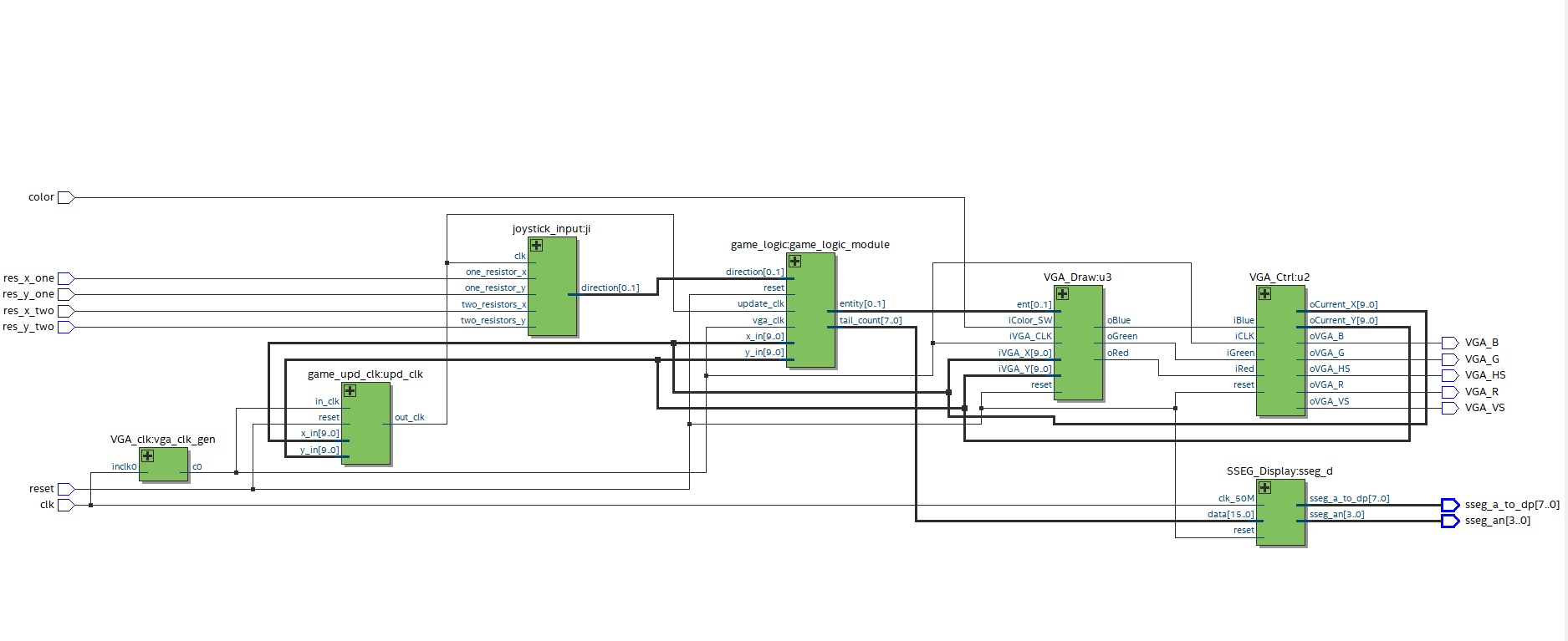
Figure 2. Top-level view of the design ( pdf )
As you can see, there are many inputs, outputs, and some modules. There are no rules for this.
Main inputs
The main inputs needed for the implementation are res_x_one , res_x_two , res_y_one , res_y_two , which are used. Figure 3 shows the directions between their values and directions.
| Input | Left | Right | Up | Down | No change in direction |
|---|---|---|---|---|---|
| res_x_one (PIN_30) | one | 0 | x | x | one |
| res_x_two (PIN_52) | one | 0 | x | x | 0 |
| res_y_one (PIN_39) | x | x | one | 0 | one |
| res_y_two (PIN_44) | x | x | one | 0 | 0 |
Figure 3. Mapping of joystick inputs and directions
Other inputs
- clk - the board clock (PIN_23)
- reset - signal to reset the game and stop printing (PIN_58)
- color - when 1, it is possible to use colors for demonstration purposes (PIN_68)
Main modules
joystick_input
joystick_input from the joystick.
game_logic
game_logic contains all the logic needed to play a game. The module moves a snake in a given direction. Additionally, it is responsible for eating. Furthermore, it has been placed at the position.
VGA_Draw
The current position ( iVGA_X, iVGA_Y ) and the current entity ( ent ).
VGA_Ctrl
Generates a control bitstream to VGA output ( V_Sync, H_Sync, R, G, B ).
SSEG_Display 2
SSEG_Display is a driver to display the current score on the 7-segment display.
VGA_clk
VGA_clk receives a 50MHz clock and cuts it down to 25.175 MHz.
game_upd_clk
game_upd_clk
Outputs
- VGA_B - VGA blue pin (PIN_144)
- VGA_G - VGA green pin (PIN_1)
- VGA_R - VGA red pin (PIN_2)
- VGA_HS - VGA horizontal synchronization (PIN_142)
- VGA_VS - VGA vertical synchronization (PIN_143)
- sseg_a_to_dp - specifies which segments to light (PIN_115, PIN_119, PIN_120, PIN_121, PIN_124, PIN_125, PIN_126, PIN_127)
- sseg_an - specifies which of the 7 7-segment displays are used to be (PIN_128, PIN_129, PIN_132, PIN_133)
Implementation
Input with SPI joystick
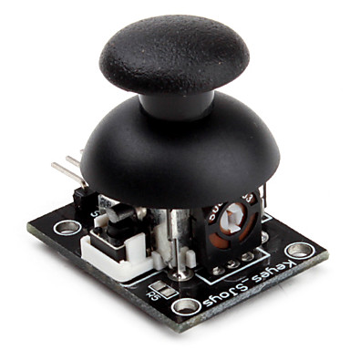
Figure 4. SPI Joystick (KY-023)
While implementing the input module The joystick has 3 positions for each axis:
- top - ~ 5V output
- mid - ~ 2.5V output
- low - ~ 0V output
The X-axis can be true (left), it can be true . FPGA board can be process Therefore, we couldn’t just write some code. This was the first time that it was possible to realize the voltage divider 3 . To define the three states, we need two bits: 00 is false , 01 is undefined and 11 is true . After some measurements, we’ve found the border between zero and one 1.7V. Thus, we built the following scheme (image created using circuitlab 4 ):
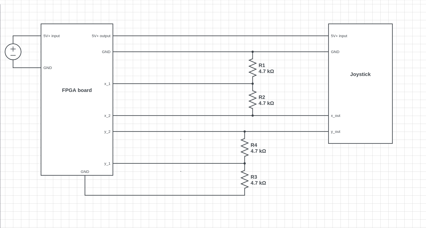
Figure 5. Circuit for ADC for joystick
The Arduino kit items are as follows:

Figure 6. ADC implementation
If it comes to the stick, it becomes a line and it becomes a line. The second is 0 at undetermined state, but still 1 at true . This is the exact result we expected.
The logic of the input module is:
- Binary wires for each direction;
- At each clock cycle, it’s
truenot possible to go by diagonal; - In the
reg left, right, up, down; initial begin direction = `TOP_DIR; end always @(posedge clk) begin //1 left = two_resistors_x; right = ~one_resistor_x; up = two_resistors_y; down = ~one_resistor_y; if (left + right + up + down == 3'b001) //2 begin if (left && (direction != `RIGHT_DIR)) //3 begin direction = `LEFT_DIR; end //same code for other directions end end Output to VGA
640x480 at a 60Hz screen running at 60 FPS.
VGA module consists of 2 main parts: a driver and a drawer . The driver generates a bitstream of horizontal and horizontal synchronization signals. An article 5 written by @SlavikMIPT describes the basic principles of working with VGA. We have adapted to our board.
We decided to break down the grid elements, square of 16x16 pixels. For each game, it is a snake's head, a tail or nothing.
The sprites for the entities.
Cyclone IV has only 3 bits to represent a color on VGA (1 for Red, 1 for Green, and 1 for Blue). The colors of images are limited to For that purpose, we’ve created a value for each pixel by 128.
from PIL import Image, ImageDraw filename = "snake_head" index = 1 im = Image.open(filename + ".png") n = Image.new('RGB', (16, 16)) d = ImageDraw.Draw(n) pix = im.load() size = im.size data = [] code = "sp[" + str(index) + "][{i}][{j}] = 3'b{RGB};\\\n" with open("code_" + filename + ".txt", 'w') as f: for i in range(size[0]): tmp = [] for j in range(size[1]): clr = im.getpixel((i, j)) vg = "{0}{1}{2}".format(int(clr[0] / 128), # an array representation for pixel int(clr[1] / 128), # since clr[*] in range [0, 255], int(clr[2] / 128)) # clr[*]/128 is either 0 or 1 tmp.append(vg) f.write(code.format(i=i, j=j, RGB=vg)) # Verilog code to initialization d.point((i, j), tuple([int(vg[0]) * 255, int(vg[1]) * 255, int(vg[2]) * 255])) # Visualize final image data.append(tmp) n.save(filename + "_3bit.png") for el in data: print(" ".join(el)) | Original | After the script |
 |  |
Figure 7. Comparison between input and output
The VGA is based on the current position ( iVGA_X, iVGA_Y ) and the current entity ( ent ). All the sprites are using the script above.
always @(posedge iVGA_CLK or posedge reset) begin if(reset) begin oRed <= 0; oGreen <= 0; oBlue <= 0; end else begin // DRAW CURRENT STATE if (ent == `ENT_NOTHING) begin oRed <= 1; oGreen <= 1; oBlue <= 1; end else begin // Drawing a particular pixel from sprite oRed <= sp[ent][iVGA_X % `H_SQUARE][iVGA_Y % `V_SQUARE][0]; oGreen <= sp[ent][iVGA_X % `H_SQUARE][iVGA_Y % `V_SQUARE][1]; oBlue <= sp[ent][iVGA_X % `H_SQUARE][iVGA_Y % `V_SQUARE][2]; end end end Output to the 7-segment display
It has been a great deal to make it clear. We used the code from EP4CE6 Starter Board Documentation 2 . This module outputs a hexadecimal number to the display.
Game logic
However, we have been able to meet the requirements of the hardware.
The module performs several functions. In the case of the VGA_Draw module, it is a model for each pixel. Module for output of coordinates.
Moreover, it was only after the screen was drawn. A signal produced by game_upd_clk module is used to determine when to update.
Game state
The game state consists of:
- Coordinates of the snake's head
- An array of coordinates of the snake's tail. The array is limited by 128 elements in our implementation
- Number of tails
- Coordinates of an apple
- Game over flag
- Game won flag
State of the game includes several stages:
- Move on the given direction. If you’re on your way, you’ll be able to move on. The X coordinate is the current coordinate system.
- New coordinates of apple coordinates:
2.1. In this case, it is not necessary to add the tail counter. It is not a sign that you can’t get anymore. The snake's head. X and y random coordinates.
2.2. In the case of the adjacent tails. (n + 1) -th tail shouldn’t be in the th tail, it was added before (n + 1) -th. The first tail of the head. - Check out the tail of your tail. If that is the case, the game stops.
Random coordinate generation
Random numbers generated by 6-bit linear-feedback shift registers (LFSR) 6 . The grid and the remainder is taken.
Conclusion
After 8 weeks of work, the project was successfully implemented. We have had some experience with the FPGA game. This is a playable language.
Acknowledgments
We have been able to express our opinion . We thank Vladislav Ostankovich for helping us with debugging. Anastassiya drawing beautiful sprites for the game. Also, we would like to extend our sincere esteems to Rabab Marouf for the proofreading and editing.
Thanks for all those who tried to set a record. Hope you enjoy playing it!
References
[1]: Project on the Github
[2]: [FPGA] EP4CE6 Starter Board Documentation
[3]: Voltage divider
[4]: Tool for modeling circuits
[5]: Altera Cyclone III VGA adapter
[6]: Linear-feedback shift register (LFSR) on Wikipedia
LFSR in an FPGA - VHDL & Verilog Code
An apple texture
Idea to generate random numbers
Palnitkar, S. (2003). Verilog HDL: A Guide to Digital Design and Synthesis, Second Edition.
')
Source: https://habr.com/ru/post/431226/
All Articles