Calculation example for a switchboard
Home Power Part Deux
In this article I want to give an example of the choice of equipment for the shield in the apartment, the conditional continuation of the previous article (some theoretical points were described there more fully). Because such a subtitle.
Initial data
Since there are, in fact, many possible conditions, here I will introduce a number of restrictions so that the example is more specific. Someone may be lucky more, someone less, but this is life.
So, there is a single-phase power supply, a meter with a rated current of 50 A is installed in the panel. The power company allows the maximum power of the input device with overload protection of 40 A. All wiring changes completely. You can replace the wiring from the source terminals of the meter (to do this, call the installer to remove the seals). If the house is normally designed and built, then something normal, like 4 mm² of copper, is laid from the meter to the panel.
As in the previous article, I proceed from the voltage in accordance with IEC standards of 230 V.
Consumption
It is important to determine what will be consumed and what currents can be expected. To do this, you need to make a list of consumers with their maximum consumption to determine the cable section. You need to understand that the maximum power connection in the above case will be only 9200 W, because at the same time turn on everything in the electric range (from 8800 to 10200 W) and then another iron (up to 2400 W) and a vacuum cleaner (900-2000 W) is not worth it. Here it is necessary to keep a balance between convenience and opportunity and sacrifice something.
')
In principle, you need to understand what works and with what power. The same washing machine consumes full power for the first 15–20 minutes while the water is heating and rinsing with powder, then the power is 10–15% of that given in the passport. Since this is all very individual, we will take the following for further calculations of large consumers (from our own experience):
- 2300 W washing machine (load 6 kg, new models)
- cooker 9200 W
- electric kettle 2000 W
- iron 2400 watts
- 1600 W vacuum cleaner
That was what the load was about. We now turn to the short-circuit currents.
Short circuit currents
Shield
As I mentioned in the previous article, the calculation will show some value, which in real life is hardly applicable, especially if the networks to which the house is connected are no longer new. In any case, to obtain data from which you can build on to calculate, are measurements. There are special devices that are essentially plugged into the outlet and measure the network resistance to this point. The device also shows the calculated value of the short circuit current at the measurement site, but this value can only be used for an overall assessment, since it is calculated on the basis of current parameters (for example, the mains voltage). Therefore, only measured resistance should be taken as a basis.
The measurement itself is also not the final answer, since short currents may change due to modifications in the network, such as repairs or equipment changes, or mode changes in medium-voltage networks. Therefore, the measured value should be “degraded” to guarantee protection even for later.
There are a number of factors that can be considered by recalculating the measured value.
First, the measurement takes place in normal conditions, and during a short circuit the wires are heated and because of this their electrical resistance increases.
Secondly, there is the measurement error of the device itself, which in some cases can be up to 30%.
Third, the influence of the medium voltage network. The maximum change in short circuit currents in the low voltage network due to changes in the medium voltage network is 10-12%.
All these factors lead to the fact that the measured resistance value should be increased 1.6-1.7 times.
Suppose the device showed a value of 0.74 ohms and a short-circuit current of 308 A when connected to the input terminals of our panel. The figure is quite large, now recalculate for the worst case.
Adjust the network resistance:
Further, we consider, according to IEC 60038, the minimum short-circuit current for mains up to 1000 V with voltage variation plus or minus 10%
As can be seen, the minimum possible short-circuit current is almost 2 times less than the calculated one.
Note
For the ordinary consumer, it is the minimum current that is important, since for him the turn-off time is critical. If you turn off the minimum, then the maximum will not be problems.
End users
So, we have a short-circuit current at the input to the shield. But the equipment built in there must protect the wires along their entire length, and not just near the shield. Then there are two options: measurement or calculation. Since I proceed from the complete replacement of the wiring, then the short currents can be calculated. If the shield and only part of the wiring changes, it is advised to carry out measurements and calculations, as indicated above.
So, the calculation. It makes sense to carry it out before starting work and buying wires to evaluate the parameters in any case. As initial values for the resistances, we take the maximum allowable resistance values from the same IEC standards (below are data only for copper):
| Section, mm² | Resistance, Ohm / km |
|---|---|
| 1.5 | 12.2 |
| 2.5 | 7.56 |
| four | 4.70 |
| 6 | 3.11 |
Further calculation. We take the following: 50 m of cable from the panel should be laid before our outlet. Suppose we choose a 2.5 mm² cable with a resistance of 12.2 ohms / km.
The network resistance at the point of connection of this outlet will be:
There are several points that are important to note. The cable resistance should be multiplied by 2, since the resistance has two conductors in the wire, and although the measured resistance is a complex value, the reactive component can be neglected for the calculation. Also, the values are given in ohm / km in the table, therefore recalculation into meters is required
Using the previously given formula, we calculate the minimum short-circuit current:
And from this result it is clear that for a guaranteed shutdown you need to take the maximum C-automat on 8 A or B-automaton on 16A.
Interesting fact
Standard switches are 10 and 16 A (in general, no matter what type). And if you take automata at 8 or less amps, it may be that their price is 1.5-2 times higher. This should be taken into account when planning, since it is impossible to eliminate breakage of the switch, and then looking for the same replacement C4A can be expensive and trite because of their rarity. Some manufacturers have automatic machines for 13A, but it’s hard to talk about pricing, someone does, like 10A, someone is more expensive.
Here it is important to note again - automatic machines protect only the cable, they do not protect against short-circuit what is connected to the socket .
What are the main disadvantages of such a calculation? We do not take into account the resistance of the terminals, for example, or the resistance of protection devices. Their resistance is small, and in principle adding 0.1–0.15 Ohm to the calculation can compensate for this inaccuracy (in the example above, the short current will be 83A, which for this case does not play a role).
Unfortunately, there are real cases (in the post-Soviet space, at least) when you buy a cable, and its real section is smaller than the written one (for example, 2.1 instead of 2.5 mm²). And if on a single-conductor wire it is still possible to check (with a caliper, for example), then for a multicore wire you can forget about it. Only measurement will help here.
The cable is sold in large pieces, you can cut the length by connecting all the conductors in series. So it will be possible to measure and calculate the actual resistance of the wire and then use this value to calculate and select automata.
Selection of protection devices for short and load currents
First, we will carry out the calculation for connecting a number of consumers, so that the example is more specific, and we will start from larger consumers to smaller ones:
Electric cooker
Copper cable 6 mm², from the shield to the outlet 15 meters.
Short circuit current:
A B-automat on 32A or C-automat on 16A is possible (A B-automaton is quite normal for a plate, but a 16A C-automaton is too small). As I wrote earlier, the total power of the plate is 9200 W, which means 40A. Since the maximum possible automaton is 32 A, it must be assumed that everything cannot be switched on immediately. What exactly - depends on consumption. In principle, for some stoves, the combination of 2 burners and an oven gives 25 A, and that can be done.
Washer
A 2.5 mm² cable is laid, from the shield to the outlet 30 meters.
Short circuit current:
Since an electric motor is built into the machine, it is worth choosing a C-automat, in this case C10A.
Electric kettle
A 2.5 mm² cable is laid, from the shield to the outlet 20 meters.
Short circuit current:
Since the electric kettle is usually not the only one turned on there (this is the kitchen), here I would advise you to choose something like 16-20.
Other electrical appliances
Here we are talking primarily about the iron or vacuum cleaner (from the large consumers I mentioned earlier). In principle, they can be included in any outlet, therefore, in the general case, it is sufficient to calculate the current for the most distant outlet (the example above is with 88.2 A and B16A is exactly the case). If it does not work out - you need to take a larger section, make inscriptions on sockets and provide special sockets for the same iron (wires for vacuum cleaners are rather long).
On the one hand, you can choose a machine for each outlet, on the other - sometimes you want unification, and it is easier when buying cables and switches, here everyone decides for himself.
For lighting, the calculation is the same, but here a wire with a cross section of 1.5 mm² is more often used, since the terminals in the kit may be suitable for multi-core 2.5 mm² and even with a squeak. But there are not such big currents, especially if we are talking about LED lighting.
Addition based on comments from 11/27/18
We are talking exclusively about lighting devices and their power. In this case, the lamp can be physically so poorly designed that 2.5 mm² will simply not fit there due to insufficient space for normal bending of the wire (I myself came across this).
The switch in this case should also be chosen for short-circuit currents, since the resistance of the conductor will be greater, then the short-circuit currents will be less, and therefore the switch will require less current (V10A instead of V16A, for example).
The switch in this case should also be chosen for short-circuit currents, since the resistance of the conductor will be greater, then the short-circuit currents will be less, and therefore the switch will require less current (V10A instead of V16A, for example).
Coordination of devices in the dashboard
So, there is the following important data:
- Max 40A Input Device
- Short circuit current in the panel 173.7 A
- Electric cooker - maximum 32
- Washing machine - C10A
- Sockets - B16A
The remaining devices are currently not important.
So, first choose the input device. To begin with, we will take several different types of switches at 40A (hereinafter the Siemens Simaris Curves program will be used, I wrote more about the programs at the end of the article) and consider the situation for the TN grounding system.
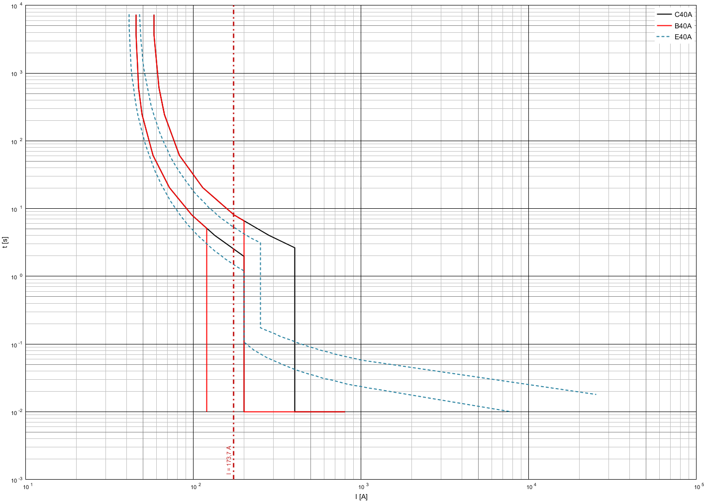
This graph shows the short-circuit current at the entrance to the shield and the curves of the switches of types B, C and E. The latter is also known as the "selective circuit breaker" (selective to the below located switches, since it turns off even large short currents with a time delay) . In this system (TN), a time of 0.4 seconds is determined for cables to outlets, while for a distribution network (what is the network between the input switch and the switches on separate branches) this time is 5 seconds. In all cases, the shutdown time is too high, namely more than 5 seconds.
Small reminder
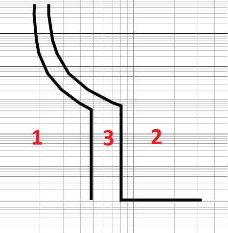
The time-current schedule of the switch and fuse (in the example below is a switch) has 3 zones: in zone 1 it should not operate, in zone 2 it must be triggered, zone 3 - tolerance according to the standards, "gray zone":
The solution in this case could be the use of a disconnector with a fusible link. Essentially an ordinary fuse, but with an appearance like a circuit breaker.
As follows:

I took for example the first picture from the Internet, the disconnector from Hager with built-in fuses of type D02 (“plugs”). It says 63A, but since the size is the same, any D02 fuse can be installed in this disconnector.
So, the time-current characteristic is as follows (gG stands for a general-purpose fuse):
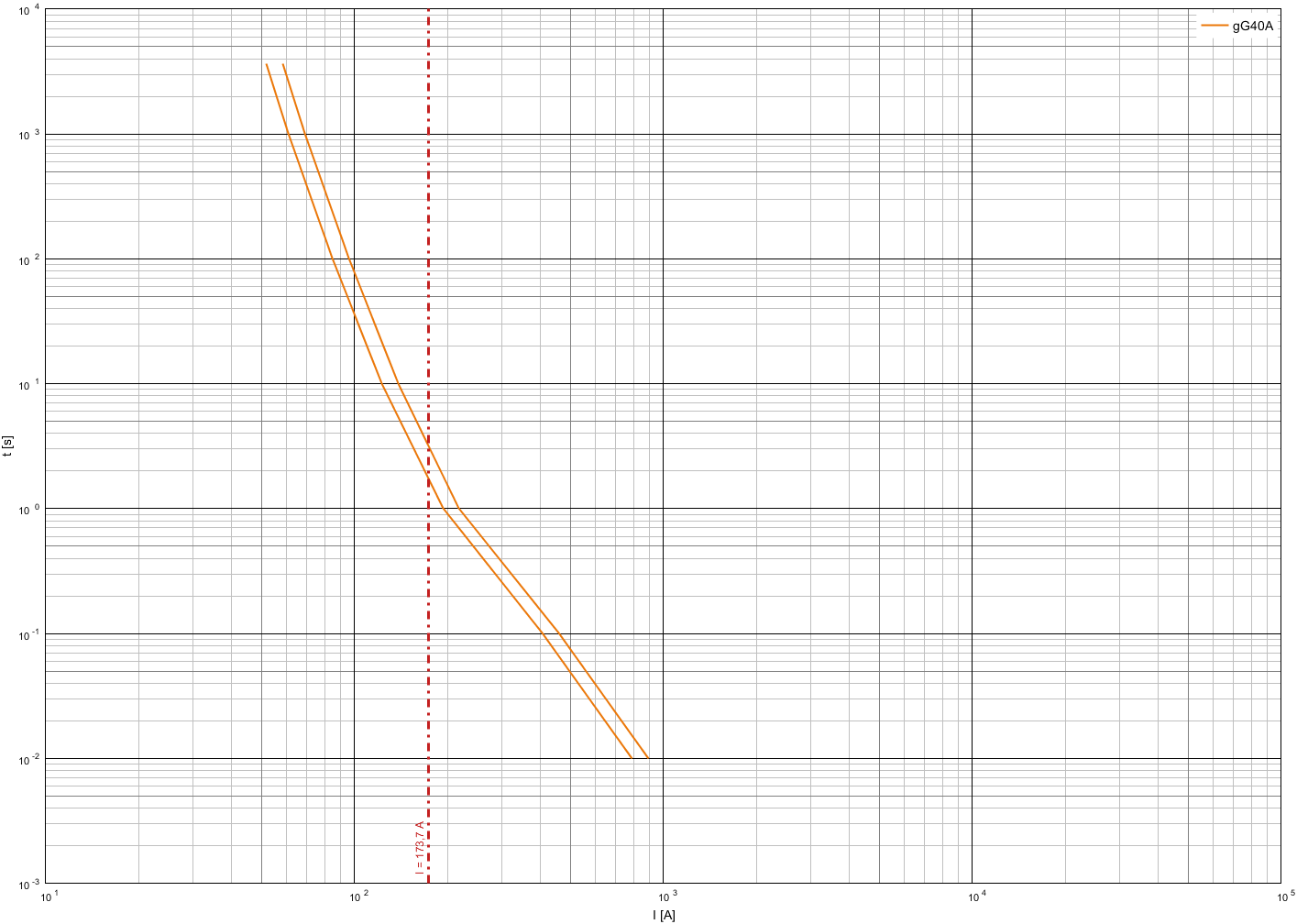
The maximum shutdown time of 3.2 seconds, which corresponds to the norms. Now let's look at the selectivity below, namely, compare with B32, B16 and C10 with the corresponding currents calculated above. Initially B32 and fuse:
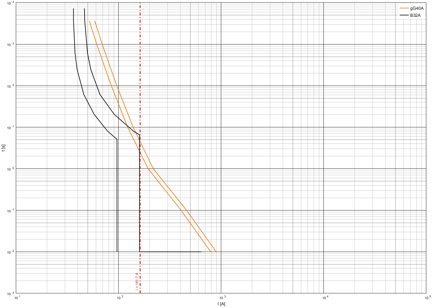
Everything is good here, from the graph you can clearly see the response time of each of the protective devices. Naturally, the situation for small switches will be better:
B16 and fuse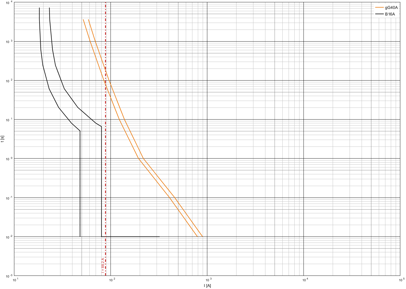
C10 and fuse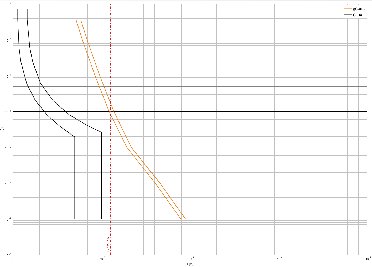
In general, for each manufacturer, there are tables of selectivity of protection devices, for example, as given below.

A small table for switches with characteristic B, a large table — C. The nominal current of the circuit breaker is highlighted by a blue, the black selectivity current on a light background is black. Both tables represent the selectivity of Siemens circuit breakers to its 40A fuse. The lack of such tables is to check all the combinations very difficult, because some cases are not even considered, although selectivity is not excluded.
Situation for the grounding system TT
In this situation, the outage in the distribution network should occur in 1 second, for end users - in 0.2 seconds (historically, these values have been formed). And if we accept that the short-circuit currents correspond to those considered earlier, then consumers will be switched off in time (the switching time of the switch is up to 0.1 second), then for the input device the situation is worse. The same 40A fuse will work in 3.2 seconds. In general, you need to go down at par:
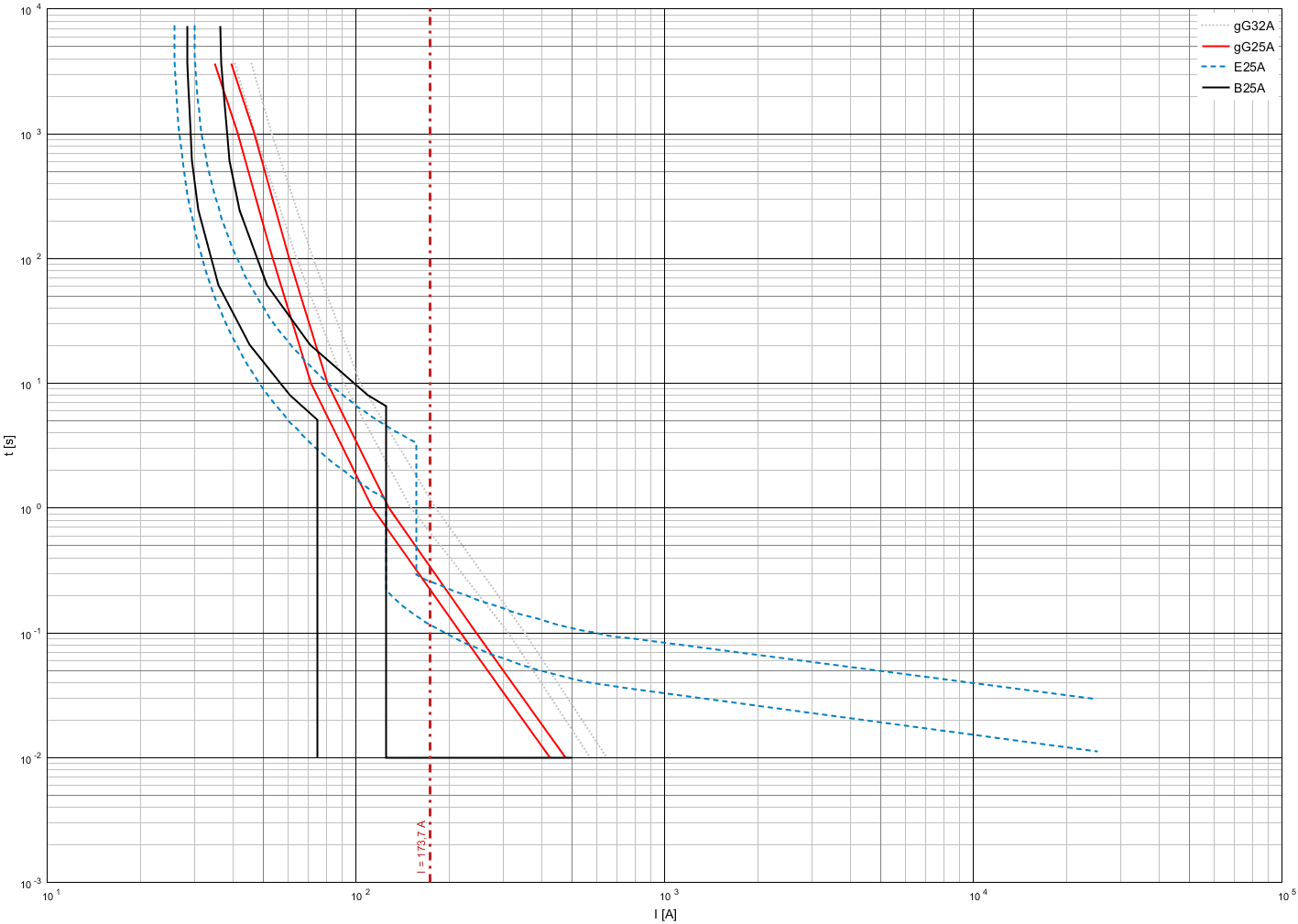
As you can see, the fuse, even at 32A, does not meet the standards for disconnecting time, but all devices at 25A can be used. In this case, it makes sense to stop at the selective switch and generally get the following picture:
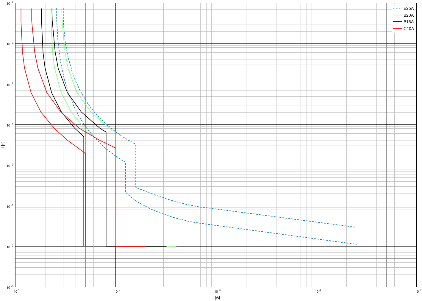
Automatic machines 16 and 10 are selective, 20 - only for the case of short circuit, but not in the case of long operation. The latter, in principle, can be applied, you just need to remember that if the selective switch was knocked out, then there could well be a problem on the load behind 20.
Additional Information
UDT differential current device
According to the recommendation of the norms, separate DCTs should be placed for each protection device against short-circuit currents and overloads. Required on-demand standards are sockets, especially where there is contact of electrical appliances with water or where there is high humidity.
The recommended circuit breakers controlled by differential current, with built-in overcurrent protection (differential circuit breakers, RCBO), as a universal and compact solution. Although the price is higher than the combination switch + UDT. There are also reasonable requirements for the use of such devices in TT systems. The reason for this for TT systems is that there is one peculiarity of closures compared to TN systems. Since, in the case of a TT system, grounding is performed not from the power source, but at the consumer’s location, the actual short-circuit current between the phase and the housing may (and most often happens) is less than between phase and neutral (in TN systems, these values are almost identical ). In fact, this is a very large differential current, but sometimes not large enough for the switch to operate, but quite reaching values that are too high for a simple UDT.
Note. UDT earlier in the norms was called RCD, according to IEC, the correct name is differential current device .
Shield size
Actually for those who have an apartment (the power company may require a main switch near the meter, but sometimes they don't care, then you can keep everything at home). There is no need to save space. It is better to take a shield that will be half empty, but it will be more convenient to work with it and there will always be an opportunity for expansion.
Programs
The programs I know are listed below. The only natural disadvantage is the use of exclusively our own equipment for low-voltage networks. All of the programs below are free, but sometimes they require free registration to download or first run. They are arranged in order of personal preference.
- Siemens Simaris Curves - the program used above has been unchanged for many years, although the comparison of the same limiting function can be improved (there is a lot to do here manually).
- ABB Curves - the last time has greatly improved, the number of functions is higher than the previous program, but sometimes a little confused. It is also possible to use IEC fuses for comparison, not only their own, albeit rather limited.
- Eaton CurveSelect - Excel-file with protection curves. Alas, only with the mandatory response curves, but not minimal, because the applicability is rather limited in the question of selectivity.
- The online resource from Schneider Electric does not work under Mozilla, on the whole is not very convenient. Here I inserted a link, because it is very difficult to find and often throws a separate program on a non-working one.
Links
- Previous article , more general
- IEC Dictionary
- Schneider Electric online electrical installation guide . English or German versions are much more complete.
Source: https://habr.com/ru/post/430922/
All Articles