Experience of using LCD displays based on MELT products
This article is devoted to an exciting adventure quest that I had to go through in the process of creating an updated external sensor for the weather station described here in this article a year and a half ago. According to the operating experience of the previous version, I really wanted to create a sensor with a control display, so that it was possible to periodically check (and verify) the most capricious component of the station without problems - the wind speed sensor. Adventures began when I began to select a display for this purpose and for a number of reasons, which I further dwelt on the products of my own MELT. But before I proceed to the description of the methods of non-traditional sex ways to cope with the works of this company chosen by me, it is worthwhile to briefly highlight the main reason for all this grandiose modernization that I started.
In the comments to that article, I was rightly pointed out with regard to the design of the sensors that the axis of such a device should have a solid edge and rest on an equally solid foundation (recall the wristwatch “on so many stones”). I knew this, of course, but then I couldn’t think of a way to provide a light axis with a tip of sufficient hardness, so, on the contrary, I took the path of minimizing friction, plunging a brass (for a weather vane) or duralumin (for a speed sensor) edge into a soft fluoroplastic (see . Drawings in this article). In the full understanding that this decision is temporary and short-lived and in the near future it is necessary to invent something more substantive.
The result of the past two seasons of operation showed nevertheless that such a solution is quite suitable for a weather vane, which, of course, cut the fluoroplastic base to the metal with a brass axis, but this did not hurt it at all - the minimum friction there is not required, even partly the other way around. It was worse with a speed sensor, in which not only the fluoroplastic at the base was sawn, but the very edge of a soft duralumin was worn out two millimeters in length. As a result, the threshold of start-up was inadmissibly increased and the sensor had to be upgraded. The anemometer itself has undergone modernization, as the laser compact disc, on the basis of which it was made, exfoliated from the sun and acquired an untidy appearance (I shouldn’t have known before that the compact discs consist of two layers).
I hope to tell you more about the new sensor later, after it has been in operation for a little while and it will be possible to make sure that nothing has to be finished in it right away (that is, not earlier than the beginning of summer). And now only some details about the changes in the measuring scheme, as they relate to the main topic of this article.
')
In connection with the lowering of the breakaway threshold, the question arose of the significant time it takes to measure low frequencies coming from the speed sensor (for details, see this publication on how to measure low frequencies). In order not to limit the breaking point artificially, in this case, frequencies should be measured, ranging from 1-2 Hz: given that the sensor has 16 holes around the circumference (see the photo of the sensor in the original article ), this corresponds to approximately one revolution in 8-16 seconds, which is known to be lower than any breakaway threshold. That is, the timeout for the arrival of the next frequency pulse must be at least 1 s (see the specified article on measurement methods), which makes the history of energy saving meaningless: in order to get an acceptable update time and at the same time have time to average the data in order to avoid display bounce, we have to wake up the controller every two seconds. And if half of them will take the waiting time of the pulses, then no energy saving will not work - considering also that all this time the emitting diode of the sensor is working, consuming about 20 mA.
It is possible to build a complex controller wake-up control from two sources: normally from an external interrupt from a speed sensor (that is, while waiting for pulses from a sensor, the controller also goes into power saving mode), and in the absence of wind - forced from Watchdog. This would make sense only if the principle of reading the speed sensor from optical to less energy-consuming circuits (which still need to be searched — the Hall sensor, for example, consumes 5-10 mA, which is fundamentally less than the optical structure) changes. But everything was simplified due to the fact that my sensor is now powered by a solar battery, which made it possible simply to abandon the energy saving mode.
To clock the readings, I didn’t bother with the timers or count down Arduyn’s millis (), but simply put a primitive external frequency generator with a period of about 1.5 seconds on the 555 timer:
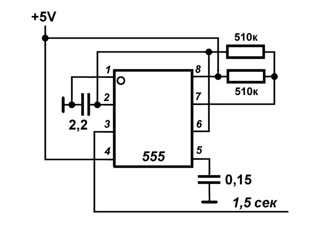
As we remember, the sensor circuit uses a “bare” Atmega328 controller in a DIP package, programmed via Uno and mounted on the panel, the Arduino itself is used only for prototyping. The output of the generator was brought to the output of the interrupt INT0, output 4 of the chip (output D2 of the Uno board). Interruption by a positive differential (RISING) sets a certain flag, by which the next readings are taken in the main cycle. The sensor frequency is also measured by the interrupt method (the sensor output is inputted to the INT1 interrupt input, pin 4 (D3), see the last method in that article ), because the maximum total waiting time is twice the measured frequency period. With a timeout of 1 s, thus, the minimum measured frequency is 2 Hz (one revolution of the anemometer in 8 seconds). In every fourth cycle, averaging occurs and the finished data is sent to the main module, that is, the readings are updated approximately every 6 seconds.
The whole story with the updated sensor will have to be calibrated and periodically checked to see if the friction has increased, comparing readings with a manual anemometer. It is therefore very inconvenient when the readings are displayed in one place (in the house), and the external sensor is installed in a completely different position - on the garden gazebo. There was a question about installing a control LCD display in the sensor housing. Since the beauty here is not required, the information requirements for it are minimal: a single-line 10-character display is enough. But the geometric requirements are quite stringent: the display must fit into the existing case in width, which is 70 mm. I must say that because of my organic dislike for LCD displays (dull, low-contrast, with small letters, disgusting quality of backlighting, and also consume a lot, what’s next), I almost don’t know about the range available in retail. And so it immediately became clear that I needed to look for the displays I needed very much: a standard 16x2 LCD display, which dominate in stores, has a board of 80 mm in length and does not fit into my sensor, and all other types are even larger, and from the firm. In nature, of course, there are varieties of smaller sizes, but then in nature, and not in domestic retail.
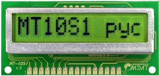
In the end, I discovered two MELTs at once, which wonderfully fit my task. The first of these is a single-line 10-character MT-10S1 with a controller, which, as the manufacturers claim, is “ similar to the HD44780 from HITACHI and KS0066 from SAMSUNG ”. It has rather large signs: more than 8 mm in height, which is generally characteristic of Chinese displays, which are much larger. The width of the board is 66 mm, the dimensions of the protruding screen (external) are 62x19.5. The consumption in this case worries me not very much (for the external sensor is powered by a solar battery of obviously more power than necessary), but out of habit, looking at the line in the datasheet, I found out that it is also less than usual - 0.7 mA (all normal LCD -displays on analogs HD44780 consume from 1.2 mA and above). There is still a highlight to the heap, as is usual for all such types - rather miserable and at the same time consuming a lot of energy.
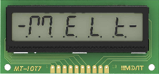
The second display MT-10T7 is even more delightful: 10 seven-segment digits as high as 13 mm fit exactly in the same dimensions. Some suspicions were caused by non-standard, and, apparently, self-made interface (for which the datasheet even gives an example of programming in a verbal pseudocode). The display does not contain a real controller: there is a set of static triggers-latches, controlled by combinational logic. But thanks to such simplicity, this whole design consumes only 30 μA, that is, it really suits devices that work on battery power around the clock (1.4 mA consumption in conventional displays and even 0.7 mA in MT-10S1 are much higher than acceptable for such use of the value - calculate for yourself how long such a display will work, even without taking into account the other components of the device, for example, from AAA batteries with a capacity of about 1500 mAh).
In short, give two!
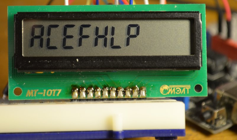
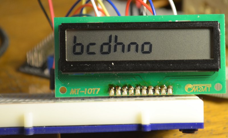
An attempt to independently reproduce the algorithm for MT-10T7, described in the datasheet (both on the Arduino and in pure assembler), did not lead to success. I did not understand what was done wrong, because I came across this publication , where the author (eshkinkot) gave a very well-written and thoroughly executed example of handling MT-10T7, after which everything worked right away. If anyone is interested, then here is a modified example of eshkinkot, supplemented by all meaningful symbols on the seven-indicator indicators, including letters that do not coincide with the numbers:
In these pictures, the contrast of the screen is slightly trimmed by setting the divider to output Vo - 18 kΩ (to power): 10 kΩ (to ground), although without it the contrast “by default” is quite acceptable.
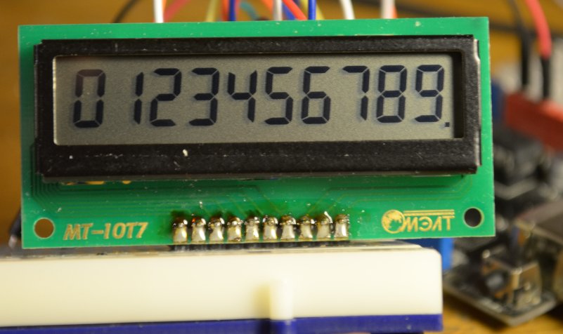
I then added a function to the given example that reproduces an arbitrary number within three to four decimal places — positive or negative, integer or floating point, that is, the total number of characters can reach five: “-12.7”, for example. Since the dot in the seven-segment code does not occupy a separate familiarity, the maximum number of output digits is 4. Input parameters for this function are: a) an array (char buf [5]) containing an ACSII representation of a number, b) the actual number of characters in it (ii from 1 to 5) and c) position (pos from 0 to 9) where to put the first (left) sign of the number (used along the way functions and designations, see the eshkinkot publication or in the example by reference):
The MT-10T7 module for the control output of numerical values is more convenient than ordinary line-matrix displays: it has large numbers and the decimal point does not occupy a separate place and, therefore, it is possible to fit one more character in the same positions. But for my purposes it is more convenient if there is a possibility of outputting letters (otherwise, the direction will have to be output in compass degrees, which is somewhat unusual). Therefore, in this case, I turned my attention to the single-size matrix MT-10S1, identical in size, which, despite a number of shortcomings, moved into the finished design. At the same time he already has a backlight, which MT-10T7 is deprived of (for this it was necessary to immediately buy MT-10T8), and I decided that in this case its presence would not hurt.
The display MT-10S1 letters-tsifirki and a half times smaller, but also quite decent size. In addition, its screen is economically packaged in general dimensions: there are no 10-digit imported counterparts, but in Vinstar WH1601L (where the characters are even slightly smaller in height) there is one millimeter more of the total length of the board and the screen. Well, almost twice the consumption of the controller (compared with the same WH1601L). Actually, this is where the advantages end, then “features” begin.
The module boasts that, as already mentioned, has a controller that is compatible with HITACHI HD44780. That is, it should work without unnecessary strains with your favorite Liquid Crystal. Moreover, the “default” page of the encoding coincides with the English-Cyrillic page of the HD44780 and its numerous analogues, that is, the MT-10S1 should work without problems with Liquid Crystal Rus, no code pages are required for this to be switched. And he really does it all, but with nuances.
The first caveat - in the single-line version, the developers, apparently, save on registers, and only 8 characters of a string (addresses 00h - 07h) fall into one register, and the remaining two characters belong to another register (40h-41h). That is, the display is de facto two-line, just the two lines are physically located in one line. Upon closer examination, it turned out that the same is true for the WH1601 (only there the second register occupies the full eight bits). Why it is so inconveniently done is completely unclear, in regular 16x2 displays the registers are sixteen-bit, and hardly such truncation reduces the price of the product, rather the opposite because of the need to produce different versions of the controller (if they are different, which I am not at all sure about). I thought it was connected with this less than usual, the consumption of MT-10S1, but the same WH1601 consumes 1.2-1.4 mA, that is, no different from its advanced counterparts.
Well, it would seem, and all right - in Liquid Crystal Rus the function setDRAMModel () and the corresponding constant LCD_DRAM_WH1601 were revealed. For such a regime, an obvious address translation is written in the library:
But I don’t know how it works on other single-line displays, and MT-10S1 in this mode refuses to work at all - the screen remains just empty. Since we are talking about addressing, you can’t fix it by a simple self-written function on top of the library, but I didn’t pick at the library and find out what was happening - I already have half a dozen Liquid Crystal versions that are already corrected, I don’t want to produce them Further.
Display MT-10S1 must be declared as two-line: lcd.begin (16, 2); (instead of 16, you can substitute 10 or 12, nothing will change, since the real number of characters in one line is still 8). Attempting to initialize it as a single-line one (tsifirka 1 in the second position) will lead to a failure — the background will turn dark. And it is possible to output multi-digit numbers only within 8 characters, for longer lines, extreme characters over 8 will simply disappear. Therefore, the 9 and 10 characters either actually are only suitable for outputting auxiliary quantities (units of measurement, for example), or you need to split the string-number into separate digits, and when switching to the 8th character, change the cursor position to the first character of the second row.
For sufferers here you can download a test sketch for this display (connection of conclusions - in the text of the sketch or in the diagram below). By the way, the contrast (about which there is not a word in the factory datasheet, and the Vo output is designated as NC) is adjusted in the usual way, but this is not really necessary: in the absence of illumination, the background seems somewhat darkish, but when you try to lighten it by connecting the divider to Vo output the contrast is noticeably lost when the backlight is on.
After checking that everything works as it should, the question of how to dock it all with the controller of the sensor rose to its full height. To provide control from it directly, the sensor controller didn’t have enough free outputs, and we didn’t want to fence the township with large controllers - it’s more convenient when the system is modular, and the display doesn’t interfere with the basic algorithm, which was already debugged earlier. It remained to use any of the serial interfaces.
This suggests an I 2 C solution based on PCF8574 (or its numerous analogs), especially since this microchip itself is just a fancy shift register, and therefore consumes several tens of μA during operation and less than 10 μA at rest. Together with the MT-10T7, they form an excellent pair for creating low-power devices with indication, and MELT even has a ready-made version for this: MT-10T11 with a total consumption of 30 μA.
But for the MT-10S1 there is no such convenient solution - for some reason, additions in the form of PCF8574 analog among MELT line displays are provided only with versions of 20x4 configuration ( UPD: in the comments it was suggested that there is still MT-16S2H configuration 16x2 with the same interface, however , his dimensions go beyond the dimensions I need). The finished module of the type described in this article is inconvenient to use in this case, since the second unpleasant feature of the MT-10S1 display is non-standard pinout. The conclusions are all the same (HD44780 after all, more precisely, its domestic analogue KB1013VG6), but they are arranged completely in a non-standard order. I checked both 16x1 and MELT's two-line / four-line for the sake of interest - they all have a standard output order, and for some reason, MT-10S1 stands out against this background. So it is necessary to fence the self-made decision.
As a result, I simply put the same ATmega328 controller on the display, which was programmed in the same way — via UNO, and then inserted into the socket on a separate board, equipped with only the necessary accessories for launching: quartz with conder, power capacity and RC circuit Reset (see the sensor circuit in the original article , where the controller is connected in a similar way).
And two identical AVR-controllers God himself ordered to dock using the usual Serial-interface, which all the same, apart from the programming process, is not used anywhere else in this project, and for the use of which everything is already at hand. By the way, such a solution does not differ from the price of components based on PCF8574 and can easily compete with it in terms of energy saving in the version with MT-10T7 - in case the MT-10T11 mentioned above is not at hand.
Total scheme of the module MT-10S1 with the controller is as follows (in the diagram the designation of the conclusions of the ATmega328 is given in brackets after the conclusions of the Arduino board):
In the controller, I applied the power saving mode (well, yes, it is not very necessary here, but why keep the chip on all the way without need?). Moreover, the awakening occurs on a signal from the same generator of the meander on a 555 chip, as the clocking of the main controller, only this time along the falling front (FALLING), in order to slightly separate the functions of measuring and sending data.
Data transfer from the sensor controller to the display controller via UART is organized in the form of a dialogue. When waking up, every 4th interrupt the display controller requests data in turn:
Here, buft, bufhh, bufss and bufd are arrays (not strings!) Of five bytes, which contain data on temperature, humidity, speed, and direction in the form of an ASCII decomposition of the corresponding numbers. In order not to take too much, an abbreviated timeout for reception is specified in setup'e:
It is more convenient to display: first, you immediately have the length of the received number, secondly, the Serial.print () function from the sensor controller side still sends an ASCII string, with the pauses set at exactly the same 10 ms between the packages :
The calculation of speed in m / s here is identical to the one that is made in the main station module (the start-off threshold is set at random to 0.3 m / s) and will also have to be changed according to the calibration results.
If you try to accept data with the usual Serial.read () and then display the result of the reception with a function like lcd.print (t, 1), where t is the temperature in degrees, for example, 12.7, then MT-10S1 responds to such the command will output "49.5". Guess or prompt? These are the first three characters in the sequence "49 50 46 55", that is, in the ASCII decomposition of the number "12.7". Therefore, it is easier to immediately receive an array of characters and directly display as many characters as were sent (count is the counter that increments each interrupt):
The last line needs decoding. The point is that the direction data is sent in code 0-15 (to which they are still transferred from the Gray code when implementing vector averaging ). In the case of the seven-segment display MT-10T7, they were converted to compass degrees:
And here we can write directly in Russian letters, as well as in the main module of the weather station (because of which this display, in fact, was chosen):
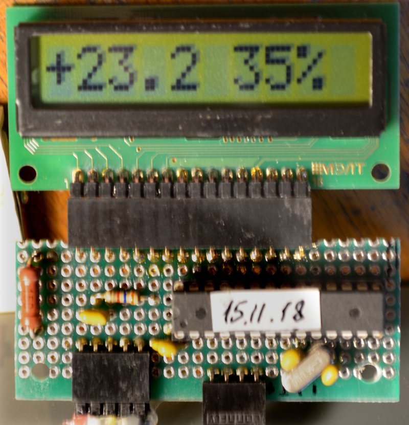
The photo shows the appearance of the display with the connected controller in working condition:
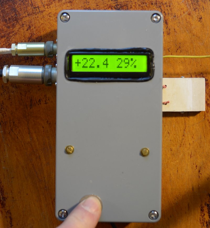
This is how the module of the modified sensor assembly looks like:
The backlight options are those shown in the diagram above. Since the voltage drop across the backlight in the MELT modules is 4.5 V, then at 12 V power supply, the backlight current is 50 mA (at the maximum for this module 60 mA).
The case is maximally sealed to avoid ingress of moist air inside (the black frame of the display screen is made of rubber sheath of a thin cable). The white plate on the right is the enclosure of the SHT-75 humidity-temperature sensor, which is outside the enclosure (the sensor itself is located behind it). The yellow wire above is a 433 MHz transmitter antenna. On the left are the connectors where the speed and direction sensors are connected.
And this is what the readings on the display of the main module of the weather station look like (the black module with the white antenna on the right is a 433 MHz receiver):

In the comments to that article, I was rightly pointed out with regard to the design of the sensors that the axis of such a device should have a solid edge and rest on an equally solid foundation (recall the wristwatch “on so many stones”). I knew this, of course, but then I couldn’t think of a way to provide a light axis with a tip of sufficient hardness, so, on the contrary, I took the path of minimizing friction, plunging a brass (for a weather vane) or duralumin (for a speed sensor) edge into a soft fluoroplastic (see . Drawings in this article). In the full understanding that this decision is temporary and short-lived and in the near future it is necessary to invent something more substantive.
The result of the past two seasons of operation showed nevertheless that such a solution is quite suitable for a weather vane, which, of course, cut the fluoroplastic base to the metal with a brass axis, but this did not hurt it at all - the minimum friction there is not required, even partly the other way around. It was worse with a speed sensor, in which not only the fluoroplastic at the base was sawn, but the very edge of a soft duralumin was worn out two millimeters in length. As a result, the threshold of start-up was inadmissibly increased and the sensor had to be upgraded. The anemometer itself has undergone modernization, as the laser compact disc, on the basis of which it was made, exfoliated from the sun and acquired an untidy appearance (I shouldn’t have known before that the compact discs consist of two layers).
I hope to tell you more about the new sensor later, after it has been in operation for a little while and it will be possible to make sure that nothing has to be finished in it right away (that is, not earlier than the beginning of summer). And now only some details about the changes in the measuring scheme, as they relate to the main topic of this article.
')
About sensor measuring circuit
In connection with the lowering of the breakaway threshold, the question arose of the significant time it takes to measure low frequencies coming from the speed sensor (for details, see this publication on how to measure low frequencies). In order not to limit the breaking point artificially, in this case, frequencies should be measured, ranging from 1-2 Hz: given that the sensor has 16 holes around the circumference (see the photo of the sensor in the original article ), this corresponds to approximately one revolution in 8-16 seconds, which is known to be lower than any breakaway threshold. That is, the timeout for the arrival of the next frequency pulse must be at least 1 s (see the specified article on measurement methods), which makes the history of energy saving meaningless: in order to get an acceptable update time and at the same time have time to average the data in order to avoid display bounce, we have to wake up the controller every two seconds. And if half of them will take the waiting time of the pulses, then no energy saving will not work - considering also that all this time the emitting diode of the sensor is working, consuming about 20 mA.
Some details in brackets
I note in parentheses that in connection with this problem, I immediately remembered the current meter, which was designed in our Design Bureau in the early eighties, even before the appearance of all sorts of controllers. The true vector averaging was implemented in it: namely, the recording of all indications was clocked by the signal from the speed sensor spinner - an approximate analogue of wake-up on external interruption. In other words, if there is no flow, then no recording was made and the circuit consumed nothing — only the real-time clock worked. The threshold of the start of the turntable, made in the form of an impeller with zero buoyancy, was, to tell the truth, 2-3 cm / sec, and the direction of the meter indicated, turning the whole body. So it is in the water, which is 700 times denser than air! During the averaging period, which made up the clock, such a turntable even once, let it rotate, because there were almost no empty measurements. And for a weather station, as already mentioned , the mathematically correct averaging method is not suitable, since even in the absence of wind, it should show something real. Therefore, here we can not do without artificially limited timeout for waiting for pulses from the sensor.
It is possible to build a complex controller wake-up control from two sources: normally from an external interrupt from a speed sensor (that is, while waiting for pulses from a sensor, the controller also goes into power saving mode), and in the absence of wind - forced from Watchdog. This would make sense only if the principle of reading the speed sensor from optical to less energy-consuming circuits (which still need to be searched — the Hall sensor, for example, consumes 5-10 mA, which is fundamentally less than the optical structure) changes. But everything was simplified due to the fact that my sensor is now powered by a solar battery, which made it possible simply to abandon the energy saving mode.
To clock the readings, I didn’t bother with the timers or count down Arduyn’s millis (), but simply put a primitive external frequency generator with a period of about 1.5 seconds on the 555 timer:
As we remember, the sensor circuit uses a “bare” Atmega328 controller in a DIP package, programmed via Uno and mounted on the panel, the Arduino itself is used only for prototyping. The output of the generator was brought to the output of the interrupt INT0, output 4 of the chip (output D2 of the Uno board). Interruption by a positive differential (RISING) sets a certain flag, by which the next readings are taken in the main cycle. The sensor frequency is also measured by the interrupt method (the sensor output is inputted to the INT1 interrupt input, pin 4 (D3), see the last method in that article ), because the maximum total waiting time is twice the measured frequency period. With a timeout of 1 s, thus, the minimum measured frequency is 2 Hz (one revolution of the anemometer in 8 seconds). In every fourth cycle, averaging occurs and the finished data is sent to the main module, that is, the readings are updated approximately every 6 seconds.
The whole story with the updated sensor will have to be calibrated and periodically checked to see if the friction has increased, comparing readings with a manual anemometer. It is therefore very inconvenient when the readings are displayed in one place (in the house), and the external sensor is installed in a completely different position - on the garden gazebo. There was a question about installing a control LCD display in the sensor housing. Since the beauty here is not required, the information requirements for it are minimal: a single-line 10-character display is enough. But the geometric requirements are quite stringent: the display must fit into the existing case in width, which is 70 mm. I must say that because of my organic dislike for LCD displays (dull, low-contrast, with small letters, disgusting quality of backlighting, and also consume a lot, what’s next), I almost don’t know about the range available in retail. And so it immediately became clear that I needed to look for the displays I needed very much: a standard 16x2 LCD display, which dominate in stores, has a board of 80 mm in length and does not fit into my sensor, and all other types are even larger, and from the firm. In nature, of course, there are varieties of smaller sizes, but then in nature, and not in domestic retail.
Solution: oh, MELT!
In the end, I discovered two MELTs at once, which wonderfully fit my task. The first of these is a single-line 10-character MT-10S1 with a controller, which, as the manufacturers claim, is “ similar to the HD44780 from HITACHI and KS0066 from SAMSUNG ”. It has rather large signs: more than 8 mm in height, which is generally characteristic of Chinese displays, which are much larger. The width of the board is 66 mm, the dimensions of the protruding screen (external) are 62x19.5. The consumption in this case worries me not very much (for the external sensor is powered by a solar battery of obviously more power than necessary), but out of habit, looking at the line in the datasheet, I found out that it is also less than usual - 0.7 mA (all normal LCD -displays on analogs HD44780 consume from 1.2 mA and above). There is still a highlight to the heap, as is usual for all such types - rather miserable and at the same time consuming a lot of energy.
The second display MT-10T7 is even more delightful: 10 seven-segment digits as high as 13 mm fit exactly in the same dimensions. Some suspicions were caused by non-standard, and, apparently, self-made interface (for which the datasheet even gives an example of programming in a verbal pseudocode). The display does not contain a real controller: there is a set of static triggers-latches, controlled by combinational logic. But thanks to such simplicity, this whole design consumes only 30 μA, that is, it really suits devices that work on battery power around the clock (1.4 mA consumption in conventional displays and even 0.7 mA in MT-10S1 are much higher than acceptable for such use of the value - calculate for yourself how long such a display will work, even without taking into account the other components of the device, for example, from AAA batteries with a capacity of about 1500 mAh).
In short, give two!
MT-10T7
An attempt to independently reproduce the algorithm for MT-10T7, described in the datasheet (both on the Arduino and in pure assembler), did not lead to success. I did not understand what was done wrong, because I came across this publication , where the author (eshkinkot) gave a very well-written and thoroughly executed example of handling MT-10T7, after which everything worked right away. If anyone is interested, then here is a modified example of eshkinkot, supplemented by all meaningful symbols on the seven-indicator indicators, including letters that do not coincide with the numbers:
In these pictures, the contrast of the screen is slightly trimmed by setting the divider to output Vo - 18 kΩ (to power): 10 kΩ (to ground), although without it the contrast “by default” is quite acceptable.
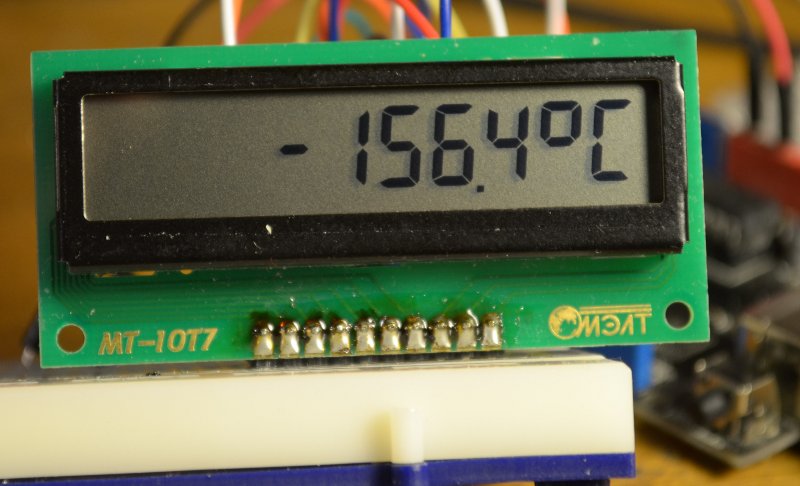
I then added a function to the given example that reproduces an arbitrary number within three to four decimal places — positive or negative, integer or floating point, that is, the total number of characters can reach five: “-12.7”, for example. Since the dot in the seven-segment code does not occupy a separate familiarity, the maximum number of output digits is 4. Input parameters for this function are: a) an array (char buf [5]) containing an ACSII representation of a number, b) the actual number of characters in it (ii from 1 to 5) and c) position (pos from 0 to 9) where to put the first (left) sign of the number (used along the way functions and designations, see the eshkinkot publication or in the example by reference):
Function code
void writeASCIIdig_serial(char buf[5], byte ii, byte pos) // { boolean dot; // // , pos: pos=pos+(4-ii); // , : for (byte i=0; i <= ii; i++) if (buf[i]=='.') pos++; // : for (byte i=0; i <= ii; i++){ // . , : if (buf[i+1]=='.') dot=true; else dot=false; switch (buf[i]) { //decoder ASCII -> 7- case '0': writeSymbol(pos, DIGIT_ZERO, dot); break; case '1': writeSymbol(pos, DIGIT_ONE, dot); break; case '2': writeSymbol(pos, DIGIT_TWO, dot); break; case '3': writeSymbol(pos, DIGIT_THREE, dot); break; case '4': writeSymbol(pos, DIGIT_FOUR, dot); break; case '5': writeSymbol(pos, DIGIT_FIVE, dot); break; case '6': writeSymbol(pos, DIGIT_SIX, dot); break; case '7': writeSymbol(pos, DIGIT_SEVEN, dot); break; case '8': writeSymbol(pos, DIGIT_EIGHT, dot); break; case '9': writeSymbol(pos, DIGIT_NINE, dot); break; case '-': writeSymbol(pos, SYMBOL_MINUS, dot); break; } //end decoder if (buf[i]!='.') pos++; // , +1 }//end for i } The MT-10T7 module for the control output of numerical values is more convenient than ordinary line-matrix displays: it has large numbers and the decimal point does not occupy a separate place and, therefore, it is possible to fit one more character in the same positions. But for my purposes it is more convenient if there is a possibility of outputting letters (otherwise, the direction will have to be output in compass degrees, which is somewhat unusual). Therefore, in this case, I turned my attention to the single-size matrix MT-10S1, identical in size, which, despite a number of shortcomings, moved into the finished design. At the same time he already has a backlight, which MT-10T7 is deprived of (for this it was necessary to immediately buy MT-10T8), and I decided that in this case its presence would not hurt.
MT-10S1
The display MT-10S1 letters-tsifirki and a half times smaller, but also quite decent size. In addition, its screen is economically packaged in general dimensions: there are no 10-digit imported counterparts, but in Vinstar WH1601L (where the characters are even slightly smaller in height) there is one millimeter more of the total length of the board and the screen. Well, almost twice the consumption of the controller (compared with the same WH1601L). Actually, this is where the advantages end, then “features” begin.
The module boasts that, as already mentioned, has a controller that is compatible with HITACHI HD44780. That is, it should work without unnecessary strains with your favorite Liquid Crystal. Moreover, the “default” page of the encoding coincides with the English-Cyrillic page of the HD44780 and its numerous analogues, that is, the MT-10S1 should work without problems with Liquid Crystal Rus, no code pages are required for this to be switched. And he really does it all, but with nuances.
The first caveat - in the single-line version, the developers, apparently, save on registers, and only 8 characters of a string (addresses 00h - 07h) fall into one register, and the remaining two characters belong to another register (40h-41h). That is, the display is de facto two-line, just the two lines are physically located in one line. Upon closer examination, it turned out that the same is true for the WH1601 (only there the second register occupies the full eight bits). Why it is so inconveniently done is completely unclear, in regular 16x2 displays the registers are sixteen-bit, and hardly such truncation reduces the price of the product, rather the opposite because of the need to produce different versions of the controller (if they are different, which I am not at all sure about). I thought it was connected with this less than usual, the consumption of MT-10S1, but the same WH1601 consumes 1.2-1.4 mA, that is, no different from its advanced counterparts.
Well, it would seem, and all right - in Liquid Crystal Rus the function setDRAMModel () and the corresponding constant LCD_DRAM_WH1601 were revealed. For such a regime, an obvious address translation is written in the library:
if (ac>7 && ac<0x14) command(LCD_SETDDRAMADDR | (0x40+ac-8)); But I don’t know how it works on other single-line displays, and MT-10S1 in this mode refuses to work at all - the screen remains just empty. Since we are talking about addressing, you can’t fix it by a simple self-written function on top of the library, but I didn’t pick at the library and find out what was happening - I already have half a dozen Liquid Crystal versions that are already corrected, I don’t want to produce them Further.
Display MT-10S1 must be declared as two-line: lcd.begin (16, 2); (instead of 16, you can substitute 10 or 12, nothing will change, since the real number of characters in one line is still 8). Attempting to initialize it as a single-line one (tsifirka 1 in the second position) will lead to a failure — the background will turn dark. And it is possible to output multi-digit numbers only within 8 characters, for longer lines, extreme characters over 8 will simply disappear. Therefore, the 9 and 10 characters either actually are only suitable for outputting auxiliary quantities (units of measurement, for example), or you need to split the string-number into separate digits, and when switching to the 8th character, change the cursor position to the first character of the second row.
For sufferers here you can download a test sketch for this display (connection of conclusions - in the text of the sketch or in the diagram below). By the way, the contrast (about which there is not a word in the factory datasheet, and the Vo output is designated as NC) is adjusted in the usual way, but this is not really necessary: in the absence of illumination, the background seems somewhat darkish, but when you try to lighten it by connecting the divider to Vo output the contrast is noticeably lost when the backlight is on.
Interface with controller
After checking that everything works as it should, the question of how to dock it all with the controller of the sensor rose to its full height. To provide control from it directly, the sensor controller didn’t have enough free outputs, and we didn’t want to fence the township with large controllers - it’s more convenient when the system is modular, and the display doesn’t interfere with the basic algorithm, which was already debugged earlier. It remained to use any of the serial interfaces.
This suggests an I 2 C solution based on PCF8574 (or its numerous analogs), especially since this microchip itself is just a fancy shift register, and therefore consumes several tens of μA during operation and less than 10 μA at rest. Together with the MT-10T7, they form an excellent pair for creating low-power devices with indication, and MELT even has a ready-made version for this: MT-10T11 with a total consumption of 30 μA.
But for the MT-10S1 there is no such convenient solution - for some reason, additions in the form of PCF8574 analog among MELT line displays are provided only with versions of 20x4 configuration ( UPD: in the comments it was suggested that there is still MT-16S2H configuration 16x2 with the same interface, however , his dimensions go beyond the dimensions I need). The finished module of the type described in this article is inconvenient to use in this case, since the second unpleasant feature of the MT-10S1 display is non-standard pinout. The conclusions are all the same (HD44780 after all, more precisely, its domestic analogue KB1013VG6), but they are arranged completely in a non-standard order. I checked both 16x1 and MELT's two-line / four-line for the sake of interest - they all have a standard output order, and for some reason, MT-10S1 stands out against this background. So it is necessary to fence the self-made decision.
As a result, I simply put the same ATmega328 controller on the display, which was programmed in the same way — via UNO, and then inserted into the socket on a separate board, equipped with only the necessary accessories for launching: quartz with conder, power capacity and RC circuit Reset (see the sensor circuit in the original article , where the controller is connected in a similar way).
By the way, about the chain of Reset
By the way, about the chain for Reset: I have a capacitor as large as 1 microfarad there on a resistor of a few kΩ, that is, the delay time when the power is turned on is several milliseconds. Is not it too much? The manual teaches us that, as for the entire Mega family, the external chain is not required here at all, the correct start is supposedly carried out by the internal scheme, and much faster. But the habit of putting an external RC chain on pin 1 of the controller to delay start up when I turned on has remained with me since the time of the already forgotten AVR Classic family, where the controller could not start correctly if the supply voltage was not sufficiently fast. And in the Mega Brown-out Detector family it may not work very well. In critical cases, it is still worthwhile to install an external power monitor, well, and here the RC-chain will not interfere with anything, but it can help in cases with poor power sources. The developers of the Arduino boards are, by the way, well aware, because on the Uno board, for example, there is the same 10 kOhm / 100 nF chain.
And two identical AVR-controllers God himself ordered to dock using the usual Serial-interface, which all the same, apart from the programming process, is not used anywhere else in this project, and for the use of which everything is already at hand. By the way, such a solution does not differ from the price of components based on PCF8574 and can easily compete with it in terms of energy saving in the version with MT-10T7 - in case the MT-10T11 mentioned above is not at hand.
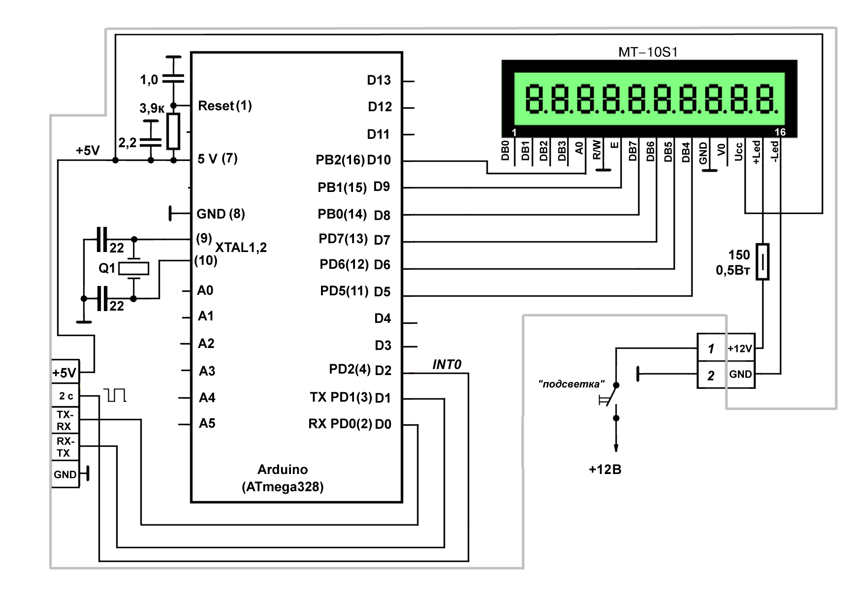
Total scheme of the module MT-10S1 with the controller is as follows (in the diagram the designation of the conclusions of the ATmega328 is given in brackets after the conclusions of the Arduino board):
In the controller, I applied the power saving mode (well, yes, it is not very necessary here, but why keep the chip on all the way without need?). Moreover, the awakening occurs on a signal from the same generator of the meander on a 555 chip, as the clocking of the main controller, only this time along the falling front (FALLING), in order to slightly separate the functions of measuring and sending data.
Mystery of nature
One mystery of nature is connected with this, which I could not solve. It is known that Mega can only be brought out of the state of deep sleep by an external asynchronous interrupt, since the clock generator is turned off and a synchronous interrupt simply cannot occur. And the whole family of 28-pin AVR controllers, leading its ATmega8 pedigree (48/88/168/328), has as such only the INT0 and INT1 interrupt for the low level (and also the PCINT interrupt, but it is not involved in the Arduino). All official recommendations are related to this in both Atmel and Arduino sites. In the example on the site arduino.cc it is directly written: " In all but the IDLE sleep modes only LOW can be used ". And as if it is not questioned, for example, Monk repeats the same in more detail in his book : “ Pay attention to the fact that the interrupt type is LOW. This is the only interrupt type that can be used in this example. The types RISING, FALLING and CHANGE will not work . ”
Interruption on a low level is very inconvenient to use, since once having occurred, with this lowest level at the output, it will happen again and again, and special measures must be taken to get rid of unnecessary alarms. So, picking on the forums in search of various solutions to this problem, I suddenly stumbled upon a couple of times on code examples in which INT0 such as RISING or FALLING is used to get out of sleep. Of course, I attributed this to the illiteracy of the authors. But when I stumbled over the phrase: “ Although you can use any other type of interrupt (RISING, FALLING, CHANGE) - they all take the processor out of sleep, ” I decided, in spite of the enemies, to conduct a live experiment - the good for that was all by hand.
And, to my amazement, everything worked fine. Power saving mode - SLEEP_MODE_PWR_DOWN; because of the uselessness here, I did not take measures to further reduce consumption by turning off all other functions, but still the clock generator is deliberately off. Nevertheless, the controller regularly wakes up on the falling edge, requests data, displays it on the display and falls asleep again. For the purity of the experiment, I removed the MK from the UNO board and inserted it into my socket with the quartz connected, and still everything continued to work. This is evident from the consumption: almost 17 mA in normal mode and 0.9-1 mA with power saving on (of which 0.7 mA should be attributed to the display).
Without leaving my bewildered state, I re-read the datasheets from Atmel, looked into Evstifeev’s book (with their translation), even looked at the old Atmel’s allowance for the Classic family, then spent half a day searching for at least some explanation of what was happening (both in Russian and in English) in two well-known to all search engines, but nowhere did he even find a hint. Unless in Atmel'ovskie Application Notes is not useful, because it is doubtful that there was published something contrary to the datasheets. I will be happy if someone who knows will explain to me what I misunderstand here.
UPD: live check in assembler (ATmega8) showed full compliance with the datasheets, that is, only the level interrupt works. The only explanation that comes to mind is that in Arduino, the PCINT interrupt was also somehow connected to the normal interrupt. An attempt to clarify the situation by studying the text of the Arduino system libraries did not give anything - the devil’s leg would break.
Data transfer from the sensor controller to the display controller via UART is organized in the form of a dialogue. When waking up, every 4th interrupt the display controller requests data in turn:
. . . . . if (flag==1) { // 4- ~6 Serial.print('T'); // while(!Serial.available()); // T iit = Serial.readBytes(buft,5); // 5 , // ii Serial.print('H'); // while(!Serial.available()); // iihh=Serial.readBytes(bufhh,5); // 5 , // ii Serial.print('S'); // while(!Serial.available()); // iiss=Serial.readBytes(bufss,5); // 5 , // ii Serial.print('D'); // while(!Serial.available()); // iid=Serial.readBytes(bufd,5); // 5 , // ii flag=0; // } . . . . . Here, buft, bufhh, bufss and bufd are arrays (not strings!) Of five bytes, which contain data on temperature, humidity, speed, and direction in the form of an ASCII decomposition of the corresponding numbers. In order not to take too much, an abbreviated timeout for reception is specified in setup'e:
. . . . . Serial.begin(9600); Serial.setTimeout(10); // 10 . . . . . It is more convenient to display: first, you immediately have the length of the received number, secondly, the Serial.print () function from the sensor controller side still sends an ASCII string, with the pauses set at exactly the same 10 ms between the packages :
. . . . . // : if (Serial.available()>0) // { char ch=Serial.read(); if (ch=='T') { Serial.print(temperature,1); delay(10);} if (ch=='H') { Serial.print(humidity,0); delay(10);} if (ch=='S') { float wFrq=(3+0.8*f)/10; // / if (wFrq>0.3) Serial.print(wFrq,1); else Serial.print(0.0,1); delay(10);} if (ch=='D') { // Serial.println(wind_G); Serial.println(wind_Avr); delay(10); }//end ch }//end serial . . . . . The calculation of speed in m / s here is identical to the one that is made in the main station module (the start-off threshold is set at random to 0.3 m / s) and will also have to be changed according to the calibration results.
If you try to accept data with the usual Serial.read () and then display the result of the reception with a function like lcd.print (t, 1), where t is the temperature in degrees, for example, 12.7, then MT-10S1 responds to such the command will output "49.5". Guess or prompt? These are the first three characters in the sequence "49 50 46 55", that is, in the ASCII decomposition of the number "12.7". Therefore, it is easier to immediately receive an array of characters and directly display as many characters as were sent (count is the counter that increments each interrupt):
. . . . if (count%8==0){ // 8 lcd.clear(); if (buft[0]!='-') lcd.print("+"); for (byte i = 0; i < iit; i++) lcd.print(buft[i]); // lcd.setCursor(6, 0); for (byte i = 0; i < iihh; i++) lcd.print(bufhh[i]); // lcd.setCursor(0, 1); lcd.print("%"); } if ((count+4)%8==0){ // 4 lcd.clear(); lcd.setCursor(0, 0); for (byte i = 0; i < iiss; i++) lcd.print(bufss[i]); // lcd.setCursor(5, 0); dir_dd(bufd); // } . . . . . The last line needs decoding. The point is that the direction data is sent in code 0-15 (to which they are still transferred from the Gray code when implementing vector averaging ). In the case of the seven-segment display MT-10T7, they were converted to compass degrees:
. . . . . dd=atoi(bufd); // dd=dd*22.5; // itoa(dd,bufd,10); // . . . . . And here we can write directly in Russian letters, as well as in the main module of the weather station (because of which this display, in fact, was chosen):
. . . . . void dir_dd(char dd[]) {switch(atoi(dd)) { case 0: {lcd.print(""); break;} case 1: {lcd.print("C"); break;} case 2: {lcd.print("C"); break;} case 3: {lcd.print("C"); break;} case 4: {lcd.print(""); break;} case 5: {lcd.print(""); break;} case 6: {lcd.print(""); break;} case 7: {lcd.print(""); break;} case 8: {lcd.print(""); break;} case 9: {lcd.print(""); break;} case 10: {lcd.print(""); break;} case 11: {lcd.print(""); break;} case 12: {lcd.print(""); break;} case 13: {lcd.print("C"); break;} case 14: {lcd.print("C"); break;} case 15: {lcd.print("C"); break;} }//end switch }//end dir . . . . . Appearance
The photo shows the appearance of the display with the connected controller in working condition:
This is how the module of the modified sensor assembly looks like:
The backlight options are those shown in the diagram above. Since the voltage drop across the backlight in the MELT modules is 4.5 V, then at 12 V power supply, the backlight current is 50 mA (at the maximum for this module 60 mA).
The case is maximally sealed to avoid ingress of moist air inside (the black frame of the display screen is made of rubber sheath of a thin cable). The white plate on the right is the enclosure of the SHT-75 humidity-temperature sensor, which is outside the enclosure (the sensor itself is located behind it). The yellow wire above is a 433 MHz transmitter antenna. On the left are the connectors where the speed and direction sensors are connected.
And this is what the readings on the display of the main module of the weather station look like (the black module with the white antenna on the right is a 433 MHz receiver):
Source: https://habr.com/ru/post/430828/
All Articles