Making a WX-Mouse in the Nova Slider 600
WX-Mouse is the creation, in any case, of a mouse with unique functionality and excellent quality of sensor operation. In this post I will tell you how to make a WX-Mouse in an unusual case - Nova Slider 600.
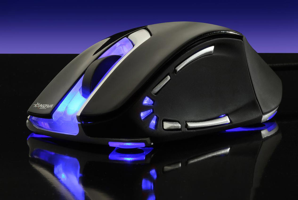
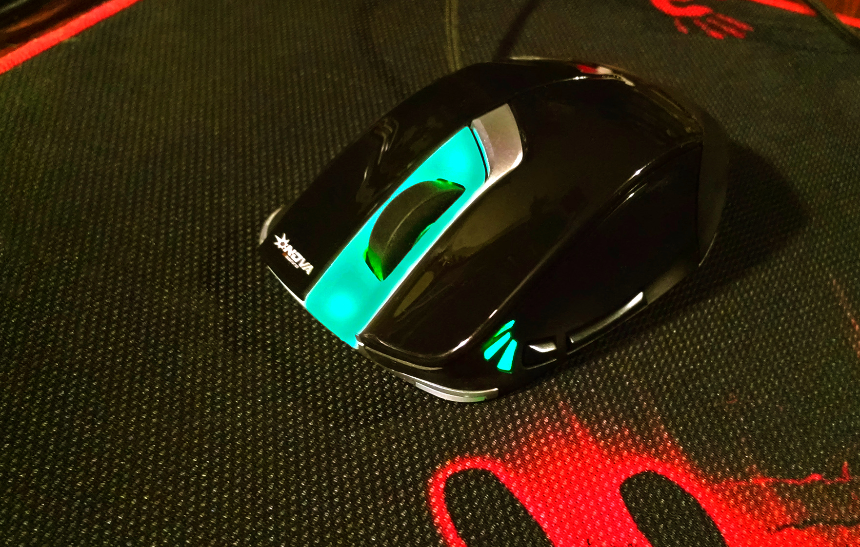
The mouse Nova Slider 600 has an unusual body. Not only is the case itself as if it were a cast from someone's hand, so also the USB cable is on the right side.
')
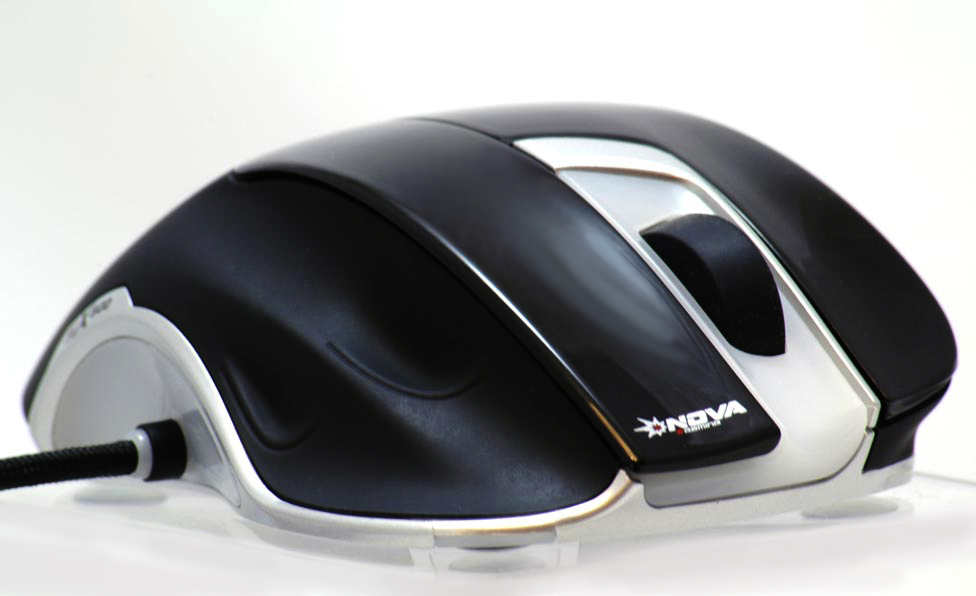
Particularly surprised by the side input of the USB cable. At first, I was skeptical about this, but after trying the mouse in the game, I agreed - this option has the right to life - the cable, even such an oak one as this mouse, was hardly felt.
“Let's go back to our sheep” - for those who do not know about the W-Mouse project, a few words about it, so that it is clear why we should redo a working mouse.
Read more about the project W-Mouse
Project W-Mouse and its development WX-Mouse, implemented Walkie .
The main advantages and features of the WX Mouse:
All this makes the WX-Mouse a unique mouse.
WX-Mouse is done as follows - take the body of a serial mouse, which satisfies the requirements of ergonomics and has the right amount of buttons. Buttons and an optical sensor (if it is suitable), as well as lights and other thingies are left in this case. Everything else - the native controller, small parts and unnecessary parts of the main board are discarded. Next, a WX-Mouse board is inserted into the case (the WX board and the sensor can be combined, and there are options when the native mouse board is completely replaced). After that, connections from the sensor, buttons and backlight to the WX board are made, the WX-Mouse firmware is blown into the controller and the WX-Mouse is ready.
W-Mouse mice are distinguished from other mice by unique functionality and high quality of work. As an illustration of this statement, I propose a comment from a person who has recently become the proud owner of a WX-Mouse - a link to the comment .
W-Mouse uses a line of "gaming" sensors, the company Avago - ADNS 6010, 6090, 3080, 3090, 9500, 9800
The WX-Mouse uses the PMW-3360 and PMW-3389 top sensors.
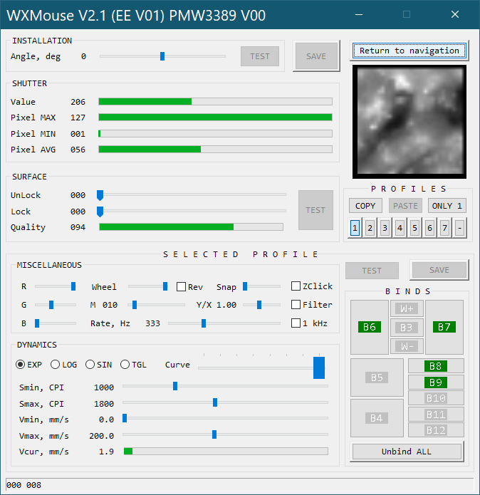
For a visual representation of the capabilities of WX-Mouse, I suggest to look at the window of its configuration program:
As an example, the mouse can be written as a pen.
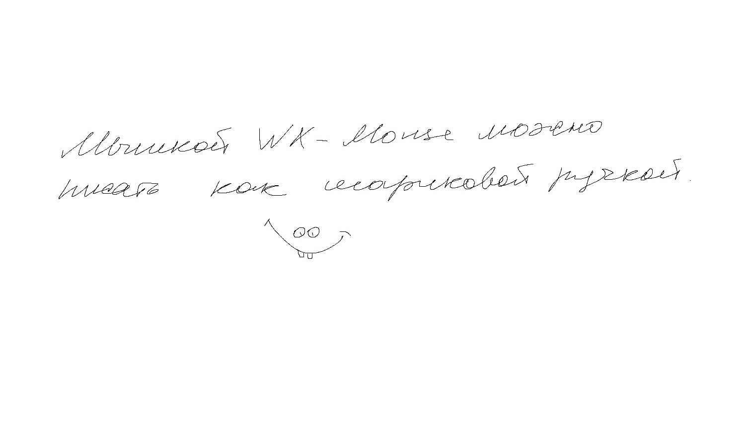
the picture is drawn in the point, with a scale of 100%, the size of the letters on the screen was 4-5 mm.
The project is discussed in the conference in the subject Laser Optical Sensor - the project W-Mouse
The main advantages and features of the WX Mouse:
- The accuracy of the sensor - the sensor during assembly, is set to the height of the best focus.
- Adjusting the dynamics of movement - the dependence of sensitivity on speed. Quite wide settings are available. For example, you can set the parameters dpi and speed, so that at low speeds the movement was pixel-by-pixel accurate, and on wide movements (sharp turns) it was not necessary to wave the mouse at half a table. It turns out a combination of high and low sense ...
- The ability to use filtering, as well as the function of a custom angular draw - increase the convenience of working in design programs.
- Display a video image of the sensor , for example, allows you to control the focus of the sensor.
- Accelerate scrolling wheel (conveniently scroll through large pages).
- Storing all settings (8 profiles) in the mouse.
- 8 profiles, each indication, customizable RGB backlighting.
- The mode of operation of the buttons Buss-keeper - increases the reliability of determining the state of the button.
All this makes the WX-Mouse a unique mouse.
WX-Mouse is done as follows - take the body of a serial mouse, which satisfies the requirements of ergonomics and has the right amount of buttons. Buttons and an optical sensor (if it is suitable), as well as lights and other thingies are left in this case. Everything else - the native controller, small parts and unnecessary parts of the main board are discarded. Next, a WX-Mouse board is inserted into the case (the WX board and the sensor can be combined, and there are options when the native mouse board is completely replaced). After that, connections from the sensor, buttons and backlight to the WX board are made, the WX-Mouse firmware is blown into the controller and the WX-Mouse is ready.
W-Mouse mice are distinguished from other mice by unique functionality and high quality of work. As an illustration of this statement, I propose a comment from a person who has recently become the proud owner of a WX-Mouse - a link to the comment .
W-Mouse uses a line of "gaming" sensors, the company Avago - ADNS 6010, 6090, 3080, 3090, 9500, 9800
The WX-Mouse uses the PMW-3360 and PMW-3389 top sensors.
For a visual representation of the capabilities of WX-Mouse, I suggest to look at the window of its configuration program:
As an example, the mouse can be written as a pen.
the picture is drawn in the point, with a scale of 100%, the size of the letters on the screen was 4-5 mm.
The project is discussed in the conference in the subject Laser Optical Sensor - the project W-Mouse
Action plan for remaking the Nova Slider 600 into a WX-Mouse
- WX board assembly with atxmega32a4u controller and sensor, controller firmware.
- Analysis of the mouse body of the patient, to decide how, what and in what order to remake.
- Completion of the bottom of the mouse to install the sensor lens PWM-3360
- Installing the WX board on the rack.
- Control of the installation height of the sensor.
- Alteration of the main board of the mouse. Replacing buttons with omron D2FC-FK (50M)
- Alteration of the side board of the mouse. Replacing buttons with omron D2FC-FK (50M)
- Matching RGB backlight.
- Wiring connectors.
- Final assembly.
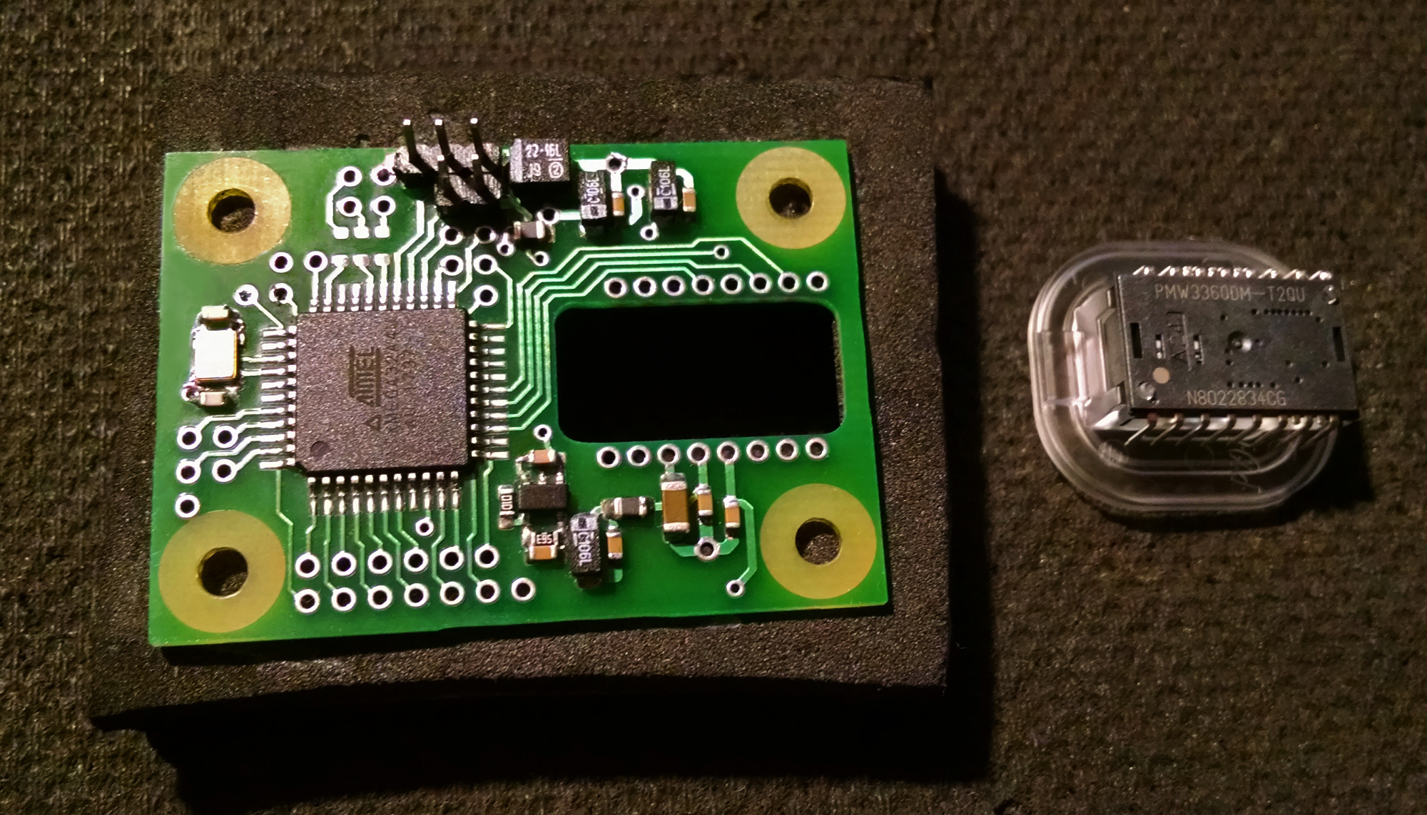
1. The WX board is assembled in the following order:
- First of all, 3 voltage stabilizers are soldered. After that, the board connects to + 5V and the tester checks that all three stubs are working normally.
- Sealed controller - atxmega32a4u
- We are flashing the controller with the programmer, we take power from the programmer board.
- We connect the WX board to the computer via USB and flash the WX-Mouse firmware into the controller. This is already done by a regular flasher.
- Seal the sensor. During soldering, it is necessary to check the tight fit of the sensor on the board and the absence of a skew in the horizontal plane.
- We put the lens, connect it to the computer and make sure that the assembled WX board is working as a mouse, i.e. bring the board to the surface and look at the movement of the cursor.
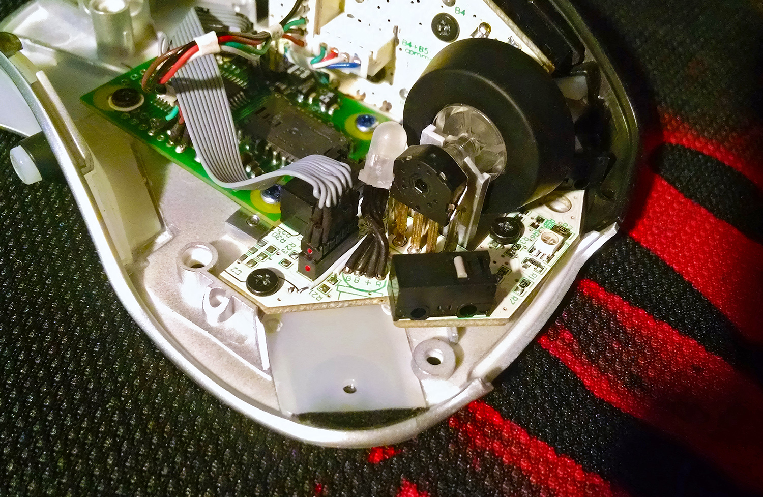
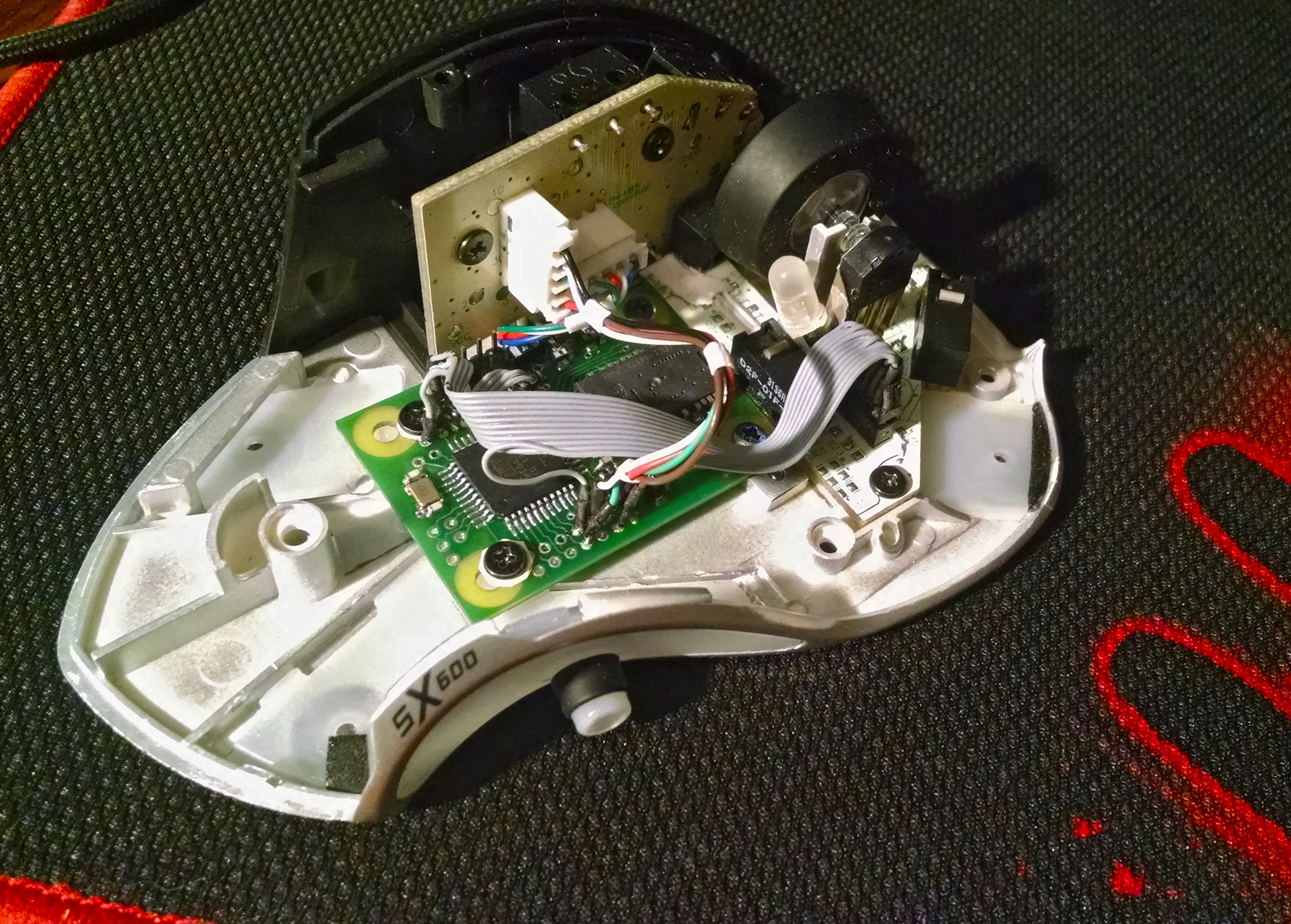
2. This is how our patient looks inside.
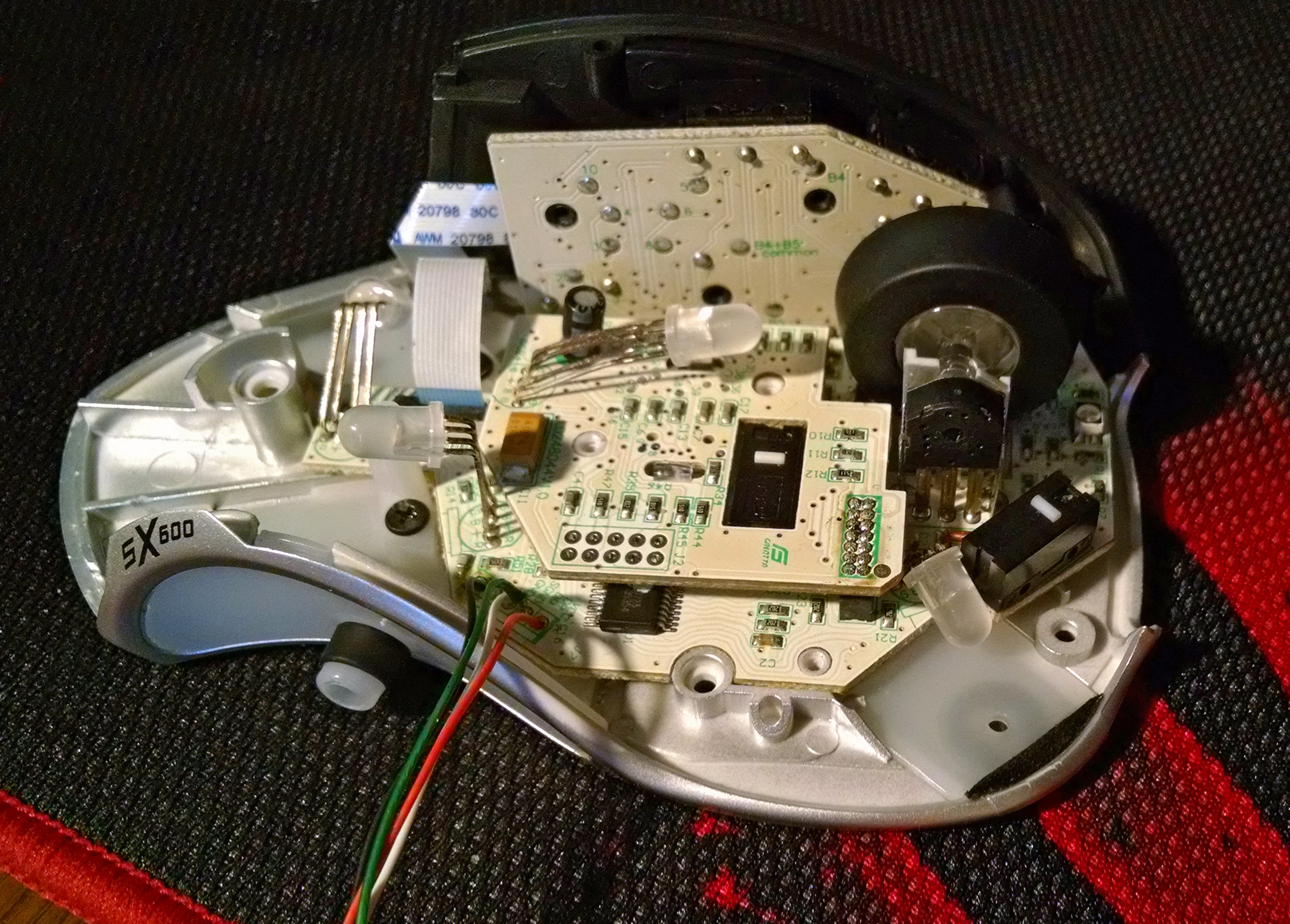

As you can see, the construction is “two-story”, but we are only interested in the main board, since as it is located on all the main buttons and wheel encoder.
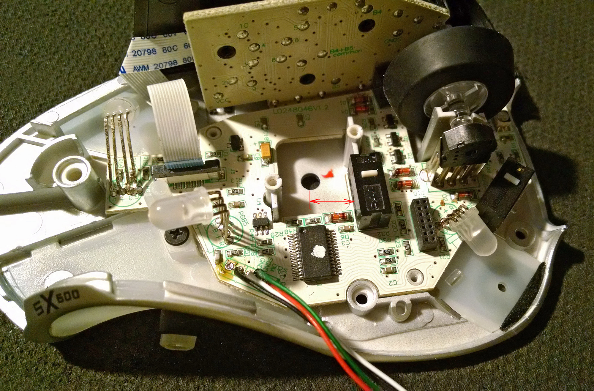
Since most of the main board will not be used and this part is located on the place where the WX board will stand, we ruthlessly cut off this unnecessary part of the main board and discard it. In this case, the main board will remain a small scrap, on which there are three main buttons, as well as an additional button, the pusher which is displayed on the back of the mouse.
It can be seen that the distance from the hole in the bottom of the sensor to the additional button on the back of the mouse is small and if you use this standard hole, the WX board stupidly does not fit - an additional button prevents. Since the customer insisted on using the standard hole, it was decided to move this button closer to the wheel.
3. In most modern mice, manufacturers put sensors at the same height. This height is determined by the distance from the working surface (pad) to the bottom surface of the lens and is 2.4mm.
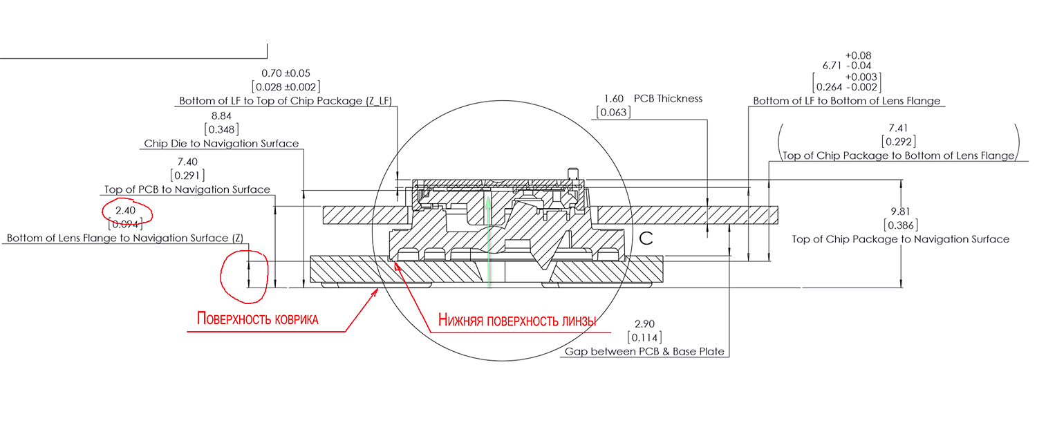
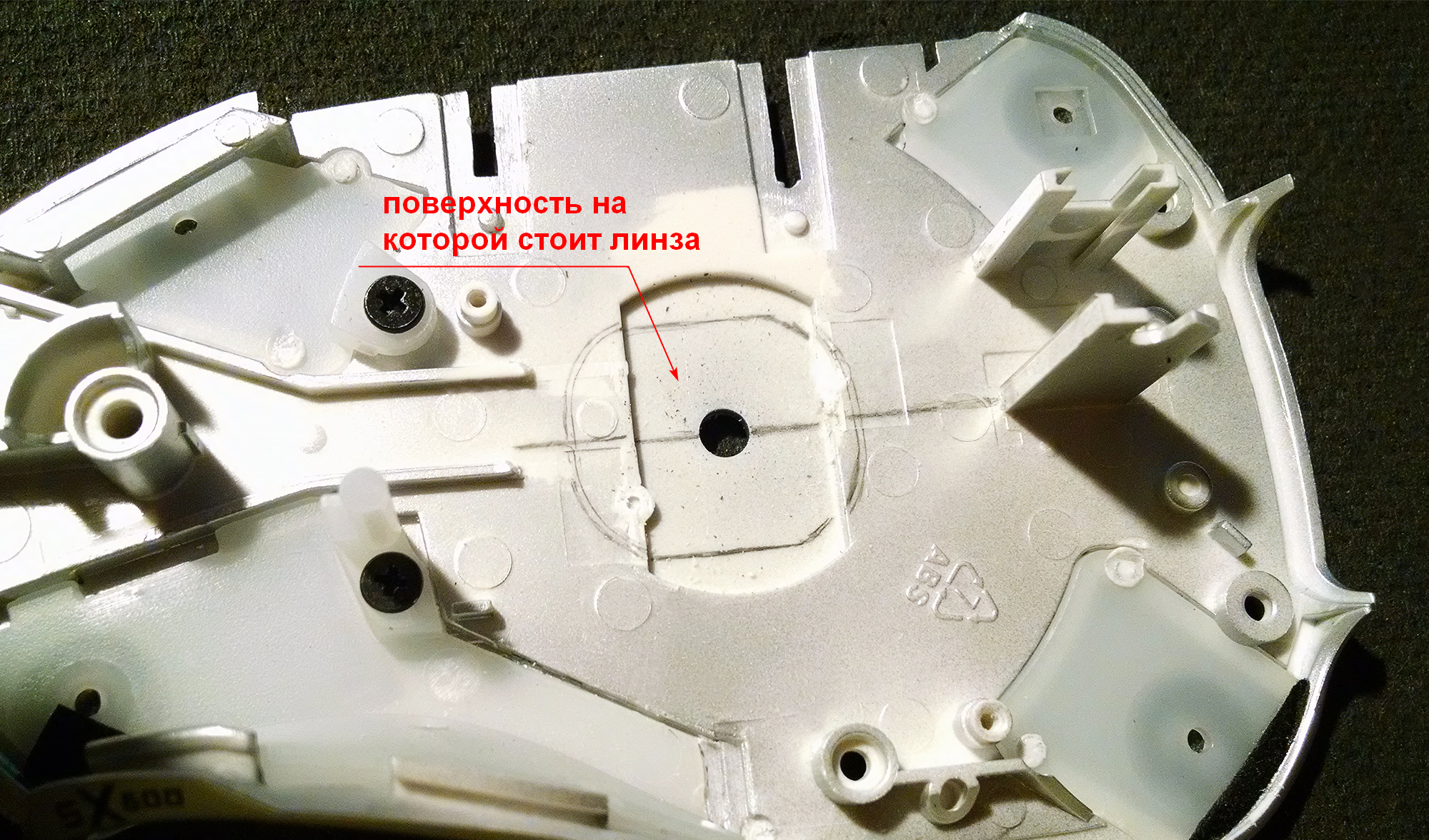
The sensor lens PWM-3360 has a shape, the contour of which is marked on the picture with a pencil line.
The extension of the lens bed is made with a Dremel, using a nozzle with side cutting edges and a flat butt.
Fitting the lens:
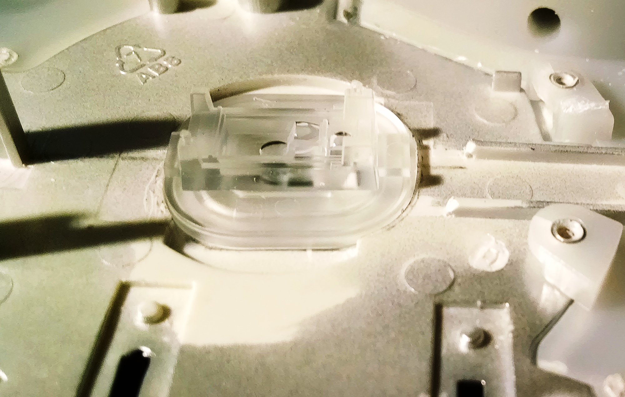
4. The bottom of this mouse has an unusual design.
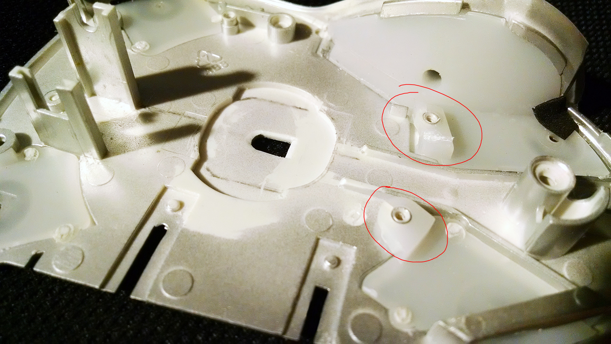
The side inserts of milky matte plastic are mounted on special racks. The location of these racks falls on the place where the WX board is put.
If you cut off these racks, you will have to somehow fix the side panels, for example with hot melt. Reliability and purely aesthetic, I did not like this option.
When fitting the WX board, it turned out that the holes in the bottom racks are located close to the mounting holes of the WX board, and just in the area where there are no tracks. Therefore, it was decided to use the available racks, only to reduce their height. For this, additional holes for the screws were made in the WX board.
As a result, the sheep are fed and the wolves are intact :)
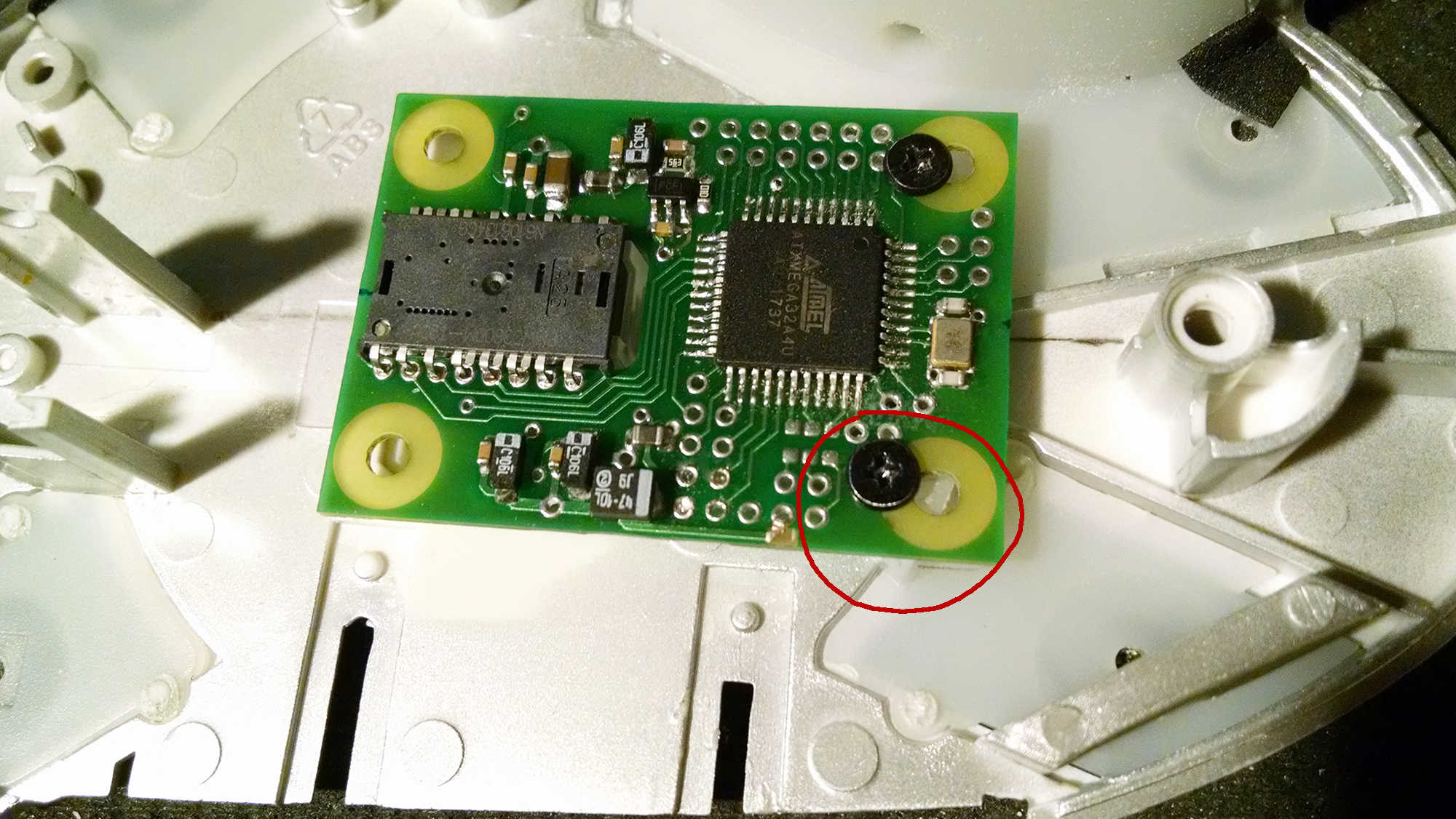
From the opposite side of the stand I made it from duralumin, their height was chosen such that the lens was pressed tightly with the WX board to the bottom surface.

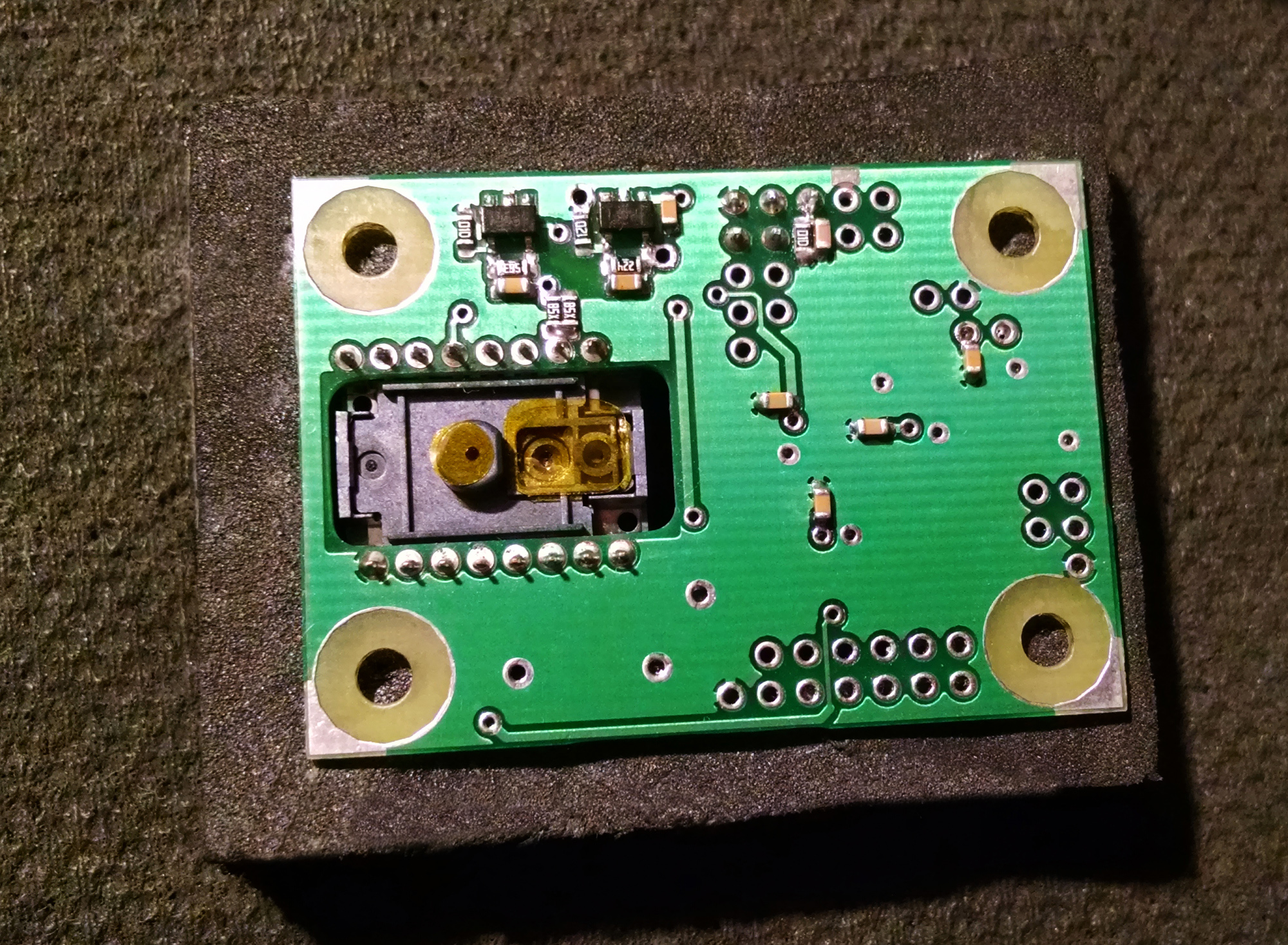
View from the bottom
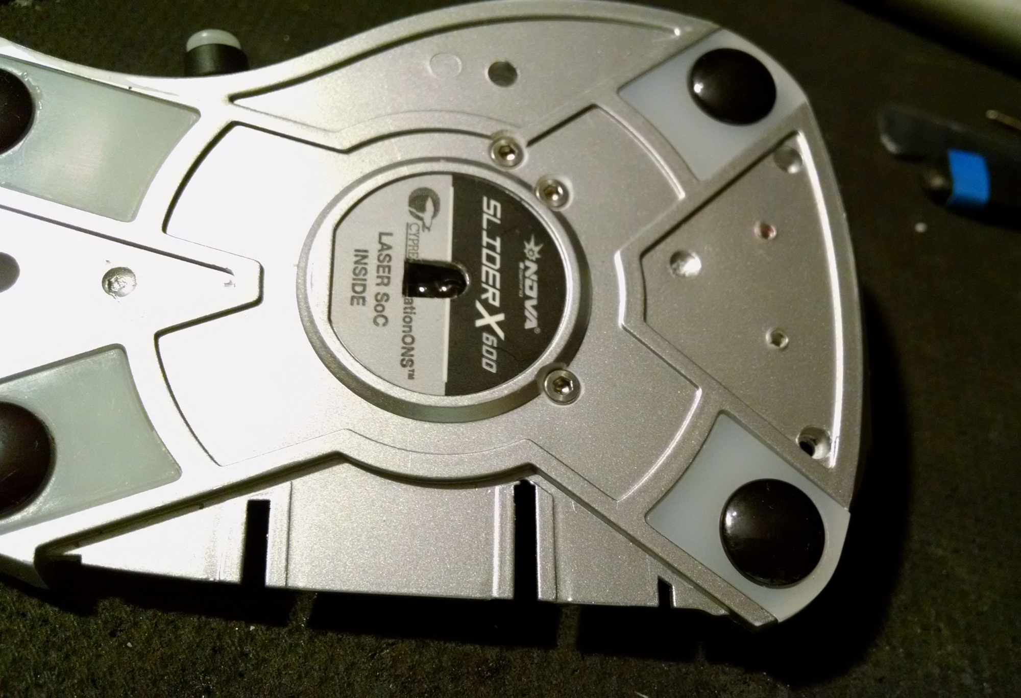
here you can see that the shape of the hole has been changed - it is made the same as the manufacturer of the sensor indicates in the datasheet.
5. At this stage, it was controlled by a video image, read from the sensor, that the height of the lens provides a good focus.
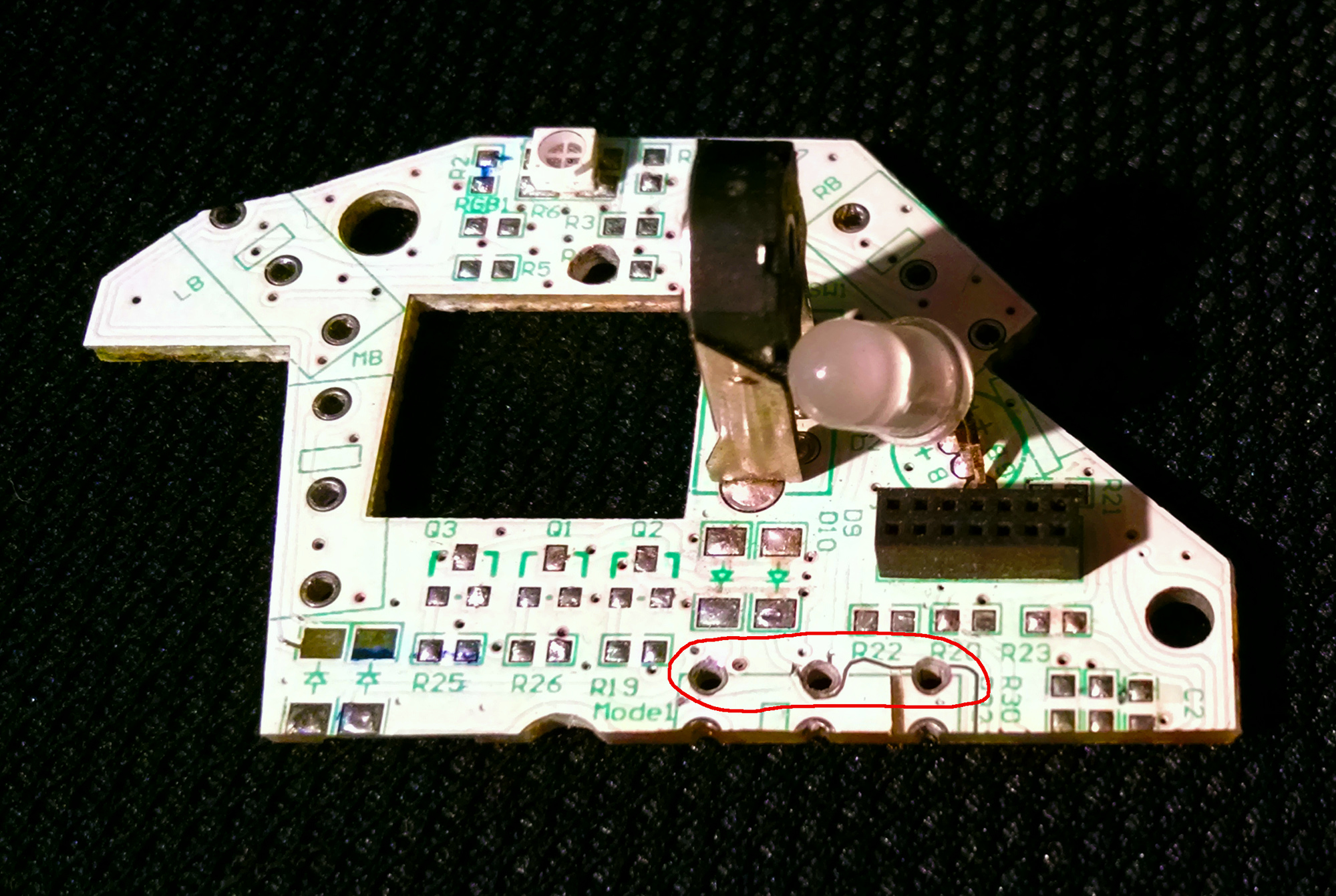
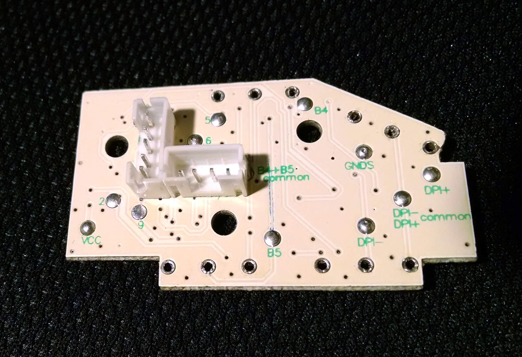
6. The main board was cut so that the WX board could be placed.

It is seen that the trimming line of the main board fell on the holes for the findings of the additional button.
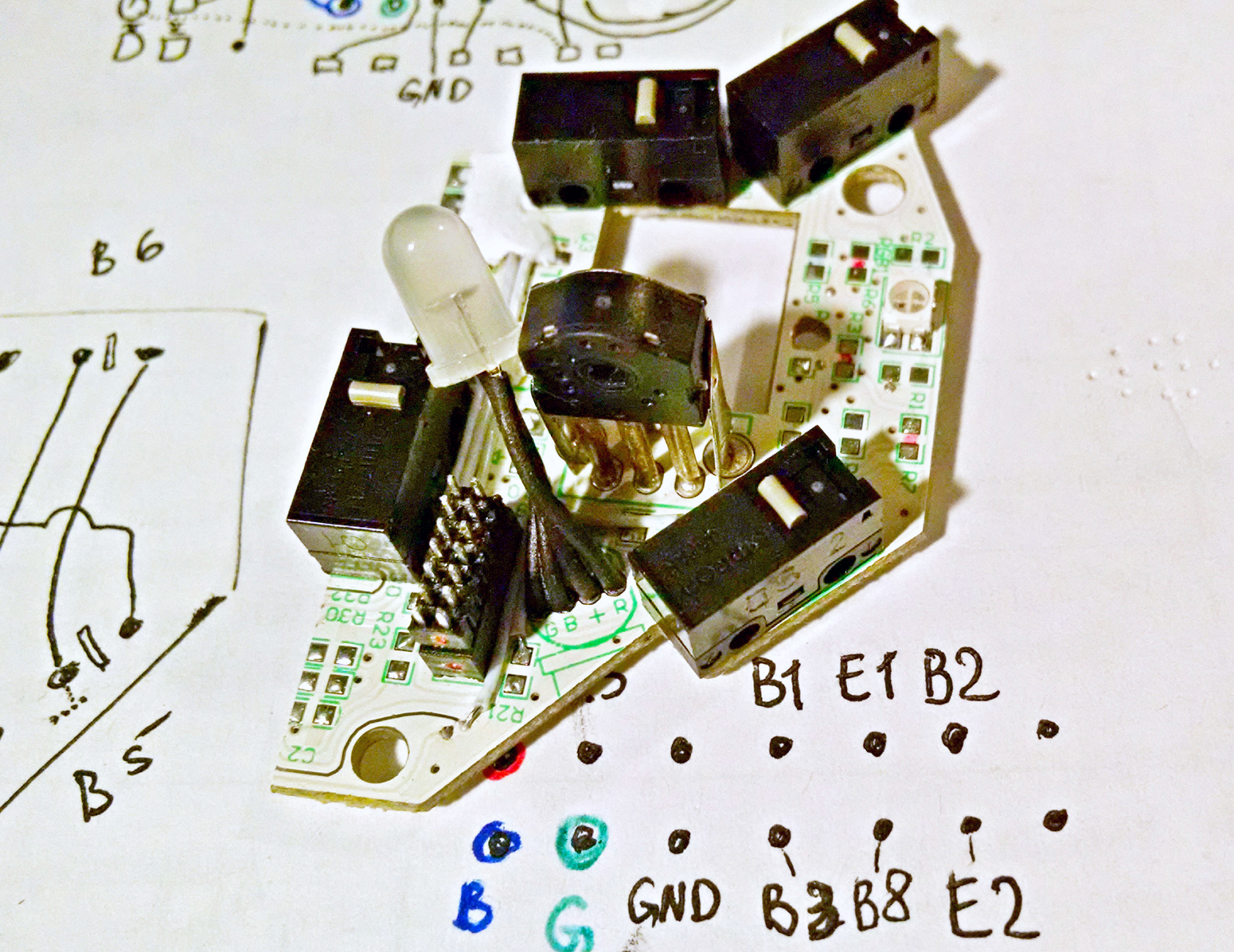
Further, this board was analyzed for the ability to connect buttons, an encoder and a backlight LED to the connector on it, with the maximum use of existing tracks. For this, the circuit of tracks on this board was “remastered” on paper.
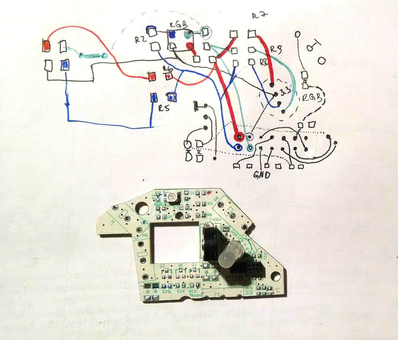
In the picture, the conductors of each of the RGB channels are drawn in their own color.
It turned out that it is possible to use almost all existing tracks. The tracks to be added are drawn with a dotted line. Very lucky that the RGB backlight wound on the connector.
For mounting an additional button, holes were drilled, offset by 3 mm in the side of the wheel.
Next, the D2FC-FK (50M) buttons were installed (the customer decided to replace all the buttons in the mouse with them at all), the RGB LED was replaced with the same one, but with longer outputs, so that the matte insert around the wheel could be highlighted. The layout of buttons on the connector.
When using the Buss-Keeper mode, the common contact or another pole must switch between two directions - this is the ground and + 3.3V.
In the microswitches that are placed in the mouse, the common contact or on the other pole is located with the edge under the button stem. This contact switches between the center pin and the far (from the stem) pin. In the unpressed state, the pole is closed at the far contact, when pressed, it is connected to the central terminal.
Most manufacturers of mice use only two outputs, and for some reason they prefer to connect the extreme output rather than the central one with the earth bus. As a result, to use the Buss-Keeper mode, when reworking into a WX-Mouse, you have to change the button layout, so that the central output is soldered to the ground.
Very lucky that the manufacturer of the buttons, were connected to the middle ground contact. This made it possible to implement the Buss-keeper mode with minimal modifications.
It was also possible to make the most of the existing tracks and almost no additional connections.

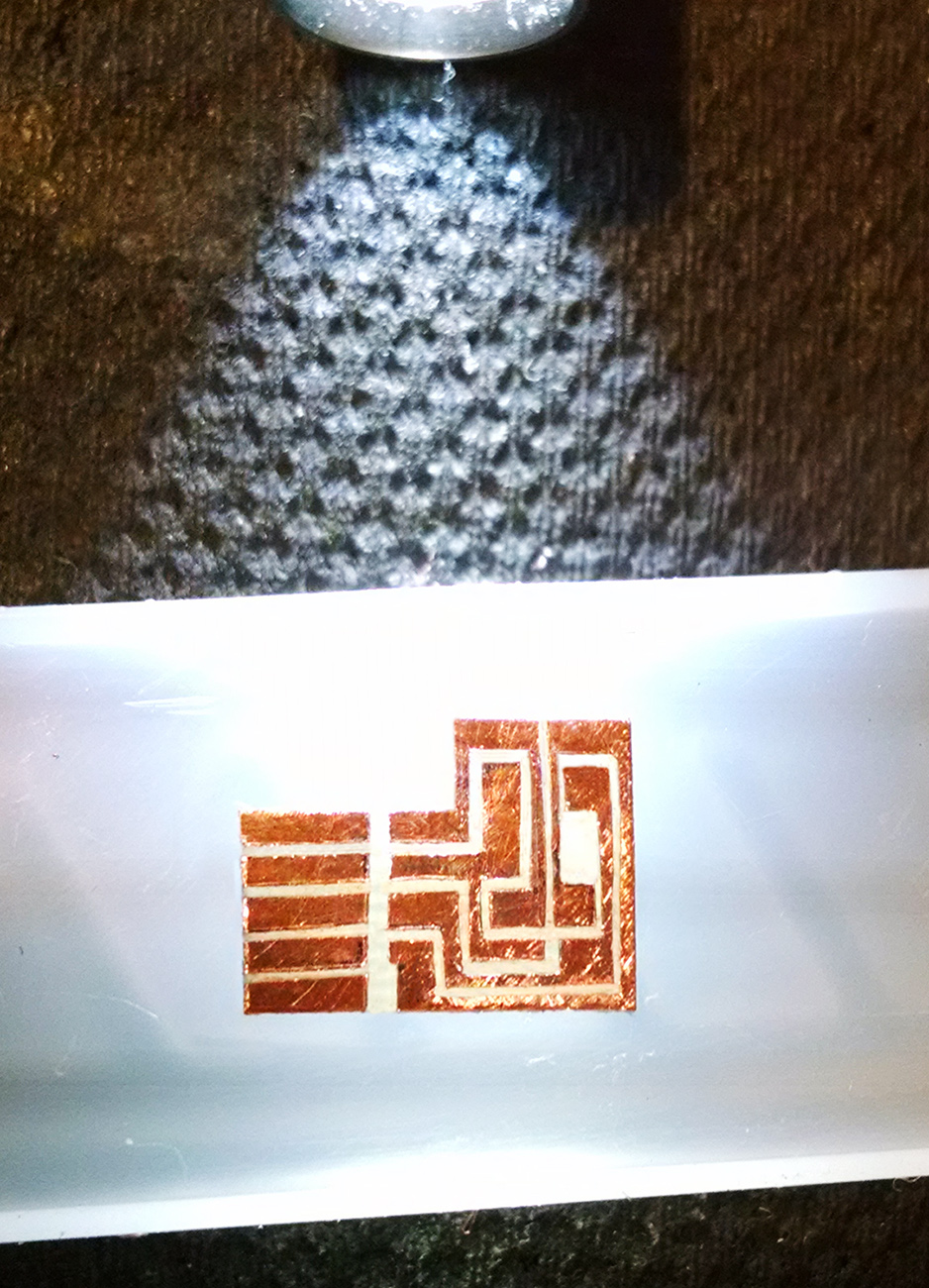
7. On the side board, the manufacturer did not use RGB LEDs, but single-color ones. Therefore, I had to make an extra small scarf with two RGB LEDs.
The scarf is primitive, so the path just cut through with a scalpel. In the picture, this board appears through the bottom, so that you can clearly see the tracks.
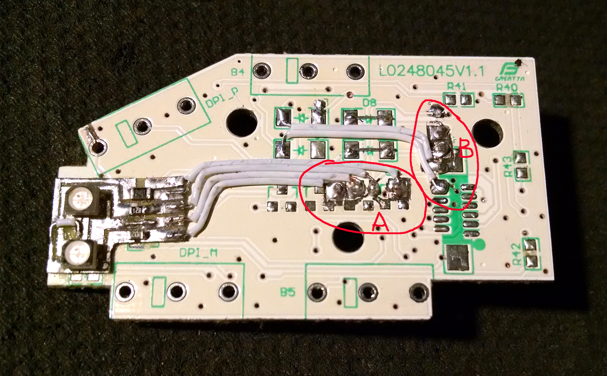
The side board was also analyzed for the use of existing tracks to connect buttons and RGB LEDs to two connectors.
After that, two connectors were put on the sideplate, as well as a small RGB backlight shawl and connections were made.
Connector A - lights, connector B - buttons and ground.
8. Matching the backlight is performed so that all its parts, illuminated by different LEDs, give the same color.
For this, resistors are selected in each of the RGB channels.
The easiest way to do this is to apply the maximum level for all three channels (+ 3.3V). In this case, as a result of mixing the three channels, the white color of the luminescence should be obtained, but since the different colors are not coordinated, the luminescence color has a certain tint. After that, the variable resistors change the brightness of each of the RGB channels, so that it turns out to be white.
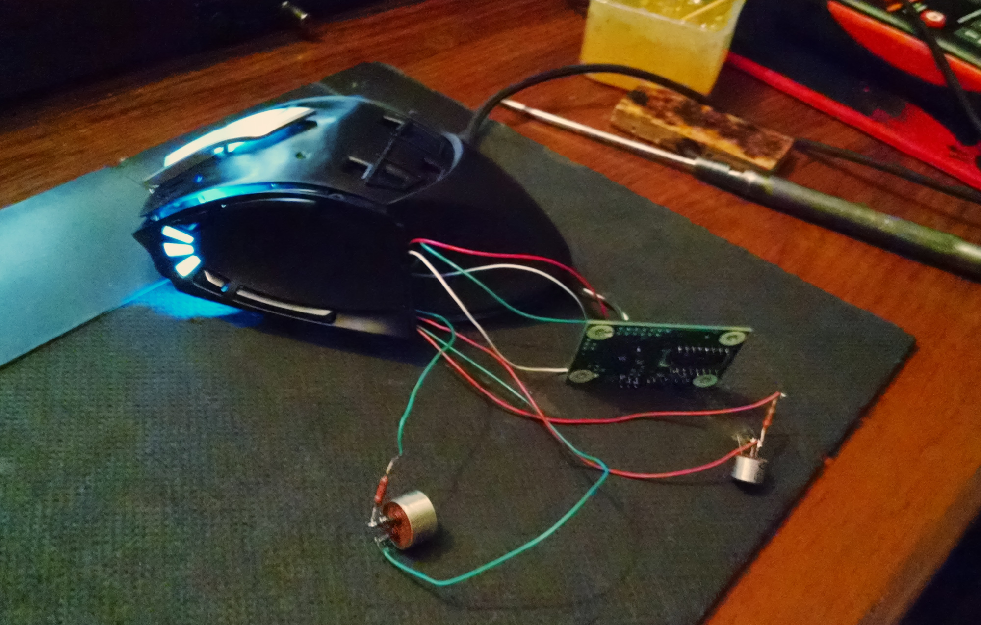
9. For the main connector, in view of its density, it was decided to use a segment of IDE ATA loop (80 cores).

After that, all the connectors on the WX board were disconnected. All boards are put in their places and connected by loops.
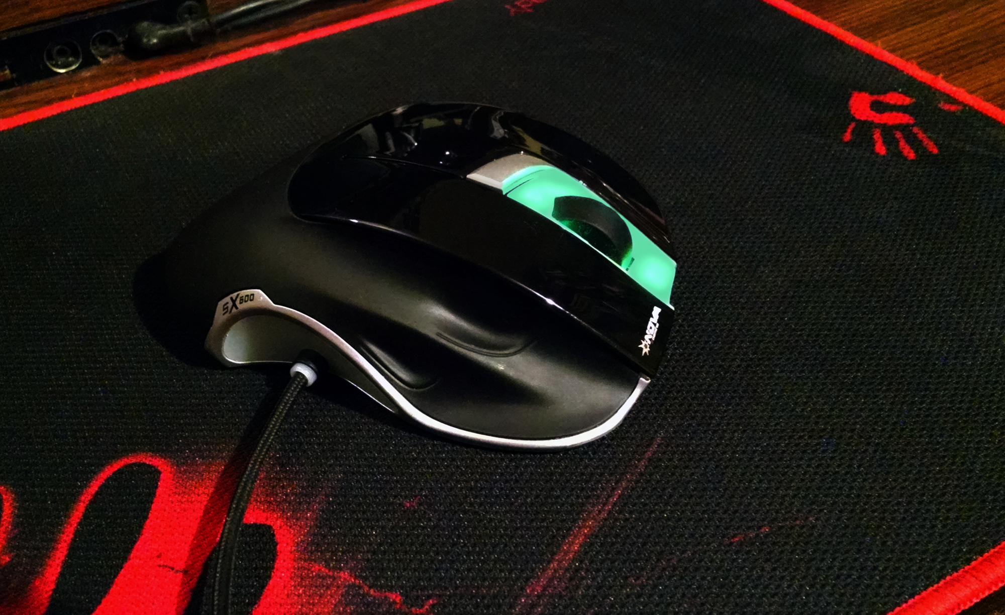
10. Produced final assembly. The mouse was tested for two days in games and sent to the customer.
For self-production of the WX-Mouse, all materials (scheme, instructions) are in the project's theme in the conference - Laser optical sensor - W-Mouse project .
There is also a discussion of the project participants, as well as laid out the latest firmware by the author of the W-Mouse - Walkie .
Thanks again to the author of the project Walkie!
Source: https://habr.com/ru/post/430756/
All Articles