Energy Optimization STM32: A Practical Guide
Hi, Habr!
There are quite a few articles about the work of STM32 microcontrollers in energy-efficient devices - as a rule, these are battery-powered devices - but among them there are regrettably few who understand this topic outside the list of energy-saving modes and SPL / HAL commands that include them (however, the same claim applies to the vast majority of articles about working with STM32).
Meanwhile, due to the rapid development of smart homes and all kinds of IoT, the topic is becoming increasingly relevant - in such systems, many components are battery powered, and they are expected to have years of continuous operation.
')
We will fill this gap with the example of the STM32L1 controller, which is a very popular controller, quite economical and at the same time having some specific problems for this series. Virtually everything said will also apply to STM32L0 and STM32L4, and, in terms of common problems and approaches, to other controllers on Cortex-M cores.
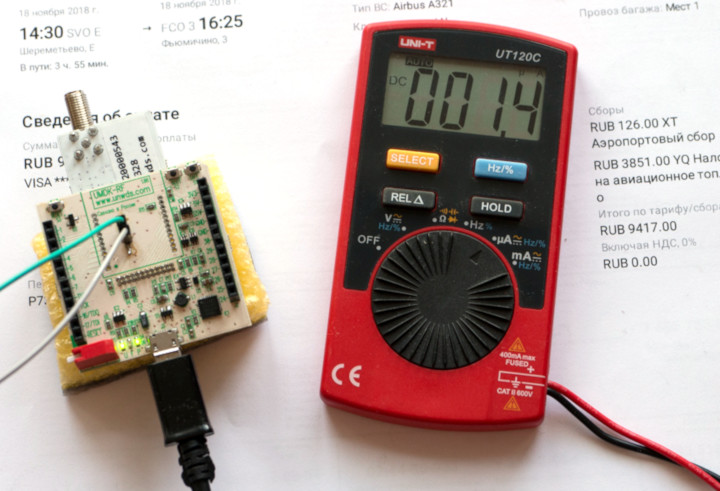
The bottom line should look something like the photo above (and yes, let's also talk about the applicability of multimeters and other measurement tools to similar tasks).
The basics of battery saving are basic processor power saving modes. They are different for each manufacturer and in each series of controllers (a specific set is a vendor extension of the standard Cortex-M core modes with different nuances regarding the periphery, supply voltages, etc.).
Specifically, the STM32L1, which belongs to an economical series of controllers and in this connection, among other things, has received an expanded set of power settings, we have the following:
Entry into each of the modes is quite simple - you need to set the flags in three to five registers, then (for sleep modes) call the WFI or WFE instruction, this is the standard Cortex-M instruction, meaning "Wait For Interrupt" and "Wait For Event" . Depending on the flags (they are described in the Reference Manual of the processor, for STM32L1 this is RM0038 ), the processor itself will fall on this command in the desired mode.
In addition, it would be nice to prohibit interruptions (this will not affect the ability of external and internal events to bring the processor out of sleep) and wait until the data has been saved from the registers to memory, if this happens suddenly, with a DSB command.
For example, this is how care in Stop mode looks like:
WFI is a blocking instruction, on it the processor will go into a deep sleep and will not get out of it until some interruption happens. Yes, I repeat, despite the fact that we have explicitly turned off the interrupts, the processor will react to them and wake up - but it will start processing only after we turn them on again. And this has a deep meaning.
In the code above, after WFI, it is not just some kind of re-initialization of operating frequencies - the fact is that from deep sleep L1 always comes out at 4.2 MHz and with an internal MSI generator as the source of this frequency. In many situations, you obviously do not want the interrupt handler to wake up the processor to start running at this frequency — for example, because the frequencies of all the timers, UART, and other buses go off; therefore, we first restore the operating frequencies (or, if we want to stay on MSI, we recalculate the necessary tires under 4.2 MHz), and then we dive into interrupts.
In practice, two modes are most often used - Run and Stop. The fact is that LP Run is painfully slow and does not make sense if the processor needs to perform some calculations, and not just wait for external events, and Sleep and LP Sleep are not very economical (consumption up to 2 mA) and needed if you need save at least a little, but at the same time leave the working periphery and / or ensure the fastest response of the processor to events. Such requirements are, but in general, not very often.
Standby mode is usually not used, because after it, because of the reset of RAM, it is impossible to continue from the same place you stopped at, and there are some problems with external devices, which we will discuss below, and which require hardware solutions. However, if the device was designed with this in mind, Standby can be used as an “off” mode, for example, during long-term storage of this device.
Actually, on the presentation of this, most manuals usually solemnly breaks off.
The problem is that by following them, you will get sad 100-200 μA of real consumption instead of the 1.4 μA promised by dataset at Stop when the clock is running - even on Nucleo's standard debugging, which has no external chips, sensors, etc. at all. on which this could be written off.
And no, your processor is healthy, there is nothing in errata, and you did everything right.
Just not to the end.
The first problem is STM32L1, about which some articles mention, but more often they recall only on the forums, when on the third day of discussion, where did those same 100-200 μA come from, someone remembers the existence of AN3430 and reaches it to page 19 - the condition of the legs by default.
I note that even STMicro itself is too casual to the question, and in most documents, where energy optimization is considered, it is limited to one or two phrases with the advice to pull unused feet to the ground or switch to analog input mode, without giving any reason.
The sadness is that by default all the legs are configured as digital inputs (0x00 in the GPIOx_MODER register). At the digital input, there is always a Schmitt trigger that improves the noise immunity of this input, while it is completely independent - this is the simplest logical element, a buffer with hysteresis, which does not require external clocking.
In our case, this means that we turned off clocking in Stop mode, and Schmitt triggers continued to work as if nothing had happened - depending on the input signal level, they switch their outputs to 0 and 1.
At the same time, part of the processor's legs in the typical scheme is hanging in the air - that is, there is no intelligible signal to them. It would be wrong to think that the lack of a clear signal means that these legs have 0 - no, these legs, due to their high input resistance, have some random interference of an unspecified size, from pickups and current flowing from neighboring tracks to the First TV channel, if the leg is long enough to serve as an antenna (however, analog TV in Russia will soon be turned off, which should lead to some reduction in power consumption of incorrectly configured microcontrollers).
In accordance with these fluctuations, the leg in some random way switches between 0 and 1. CMOS logic consumes current when switching. That is, the processor leg in the air, configured in the digital input mode, consumes a noticeable current by itself .
The way out of this is simple - when starting the program, all the legs need to be configured in the analog input state; for STM32, it is formally available for all legs without exception, regardless of whether they are connected to the ADC or not, and differs from the digital input only by the absence of a Schmitt trigger at the input.
To do this, it is enough to write the value 0xFF ... FF to all the GPIOx_MODER registers. The easiest way to do this, as mentioned above, is right at the start, and then during the play you have to reconfigure individual legs as you need in this device.
Here, however, a second-order problem arises - it’s good if your firmware runs on one particular controller, and therefore you always know what GPIOx is equal to x . Worse, if the firmware is universal - the STM32 can have up to 8 ports, but it can be less; If you try to write to the port that does not exist in this model of the controller, you will get a Hard Fault, i.e. emergency stop the kernel.
However, even this case can be circumvented - Cortex-M allows checking addresses for their validity, and in the case of M3 and M4, the test is generally quite trivial, and on M0 it takes some magic, but is realizable ( we can’t read the details here , ).
That is, in the general case, the processor started up, tuned the frequencies - and immediately went through all the available GPIO ports, writing the ones in the MODER (the code below was written under RIOT OS, but on the whole is clear without comment and can be shifted to any other platform).
I note that this applies only to the L1 series, in L0 and L4 the experience was taken into account, and by default they start to configure all ports as analog inputs.
Having carefully done all these procedures, you fill the firmware into the ready-made device ... and get 150 µA in Stop mode on the processor and all external chips turned off, despite the fact that your most pessimistic estimates are derived from datasheets for everything that you have soldered on the board , give no higher than 10 μA.
Moreover, further you try to lead the processor to Standby instead of Stop, i.e. just turn it off almost completely - and instead of falling, the power consumption increases threefold, getting close to half a milliampere!
No need to panic. As you may have guessed, you did everything right. But not until the end.
The following problem consists of two parts.
The first one is fairly obvious: if your device does not consist of a single microcontroller, then it is important not to forget that external chips also have input signals on which Schmitt triggers hang, and which, moreover, can wake up the internal logic of the chip. For example, a chip taken away and taken out of its sleep by a UART team, during any movement on this bus, will try to read data from it.
Accordingly, if all these legs are hanged in the air, we will not get anything good.
Under what conditions are they in the air?
First, when the controller goes into Standby mode, all GPIOs are transferred to the High-Z state, with high resistance - that is, in fact, external chips connected to them are airborne. It is impossible to fix this programmatically in the STM32L1 (in other series and other controllers it happens differently), so the only way out is in the system in which Standby mode is supposed to be used, the inputs of external chips must be pulled to ground or powered by external resistors.
The specific level is chosen so that the line is inactive from the point of view of the chip:
Secondly, on STM32, when using Stop mode (sic!), The state of GPIO connected to the internal hardware interface blocks may be ... different. That is, the same SPI interface, being configured, in the Stop, suddenly it turns out to be either a digital input, or a High-Z in general - with corresponding consequences for external chips hanging on it. Given that the documentation claims the preservation of the state of the legs, a priori, you can rely on it only if you use your legs as ordinary GPIO.
You can’t understand and forgive this, but you can remember and correct it: for interfaces that behave in this way, they must be forcedly switched to regular GPIO functions with interfaces corresponding to the inactive levels of this interface. After exiting sleep, interfaces can be restored.
For example, the same SPI before going to sleep (for simplicity, I take the code from the RIOT OS OS, it is clear that the same is easy to implement on registers):
Please note that the outputs here are not configured as GPIO_OUT with a level of 0 or 1, but as inputs with a pull-up to 0 or 1 - this is not a crucial moment, but provides additional security if you make a mistake and try to play with pulling-pushing external chip pulling this leg in the other direction. A short circuit can be made with GPIO_OUT, never with a GPIO_IN with a suspender.
In addition, the SPI CS signal is not affected — in this case, it is generated by software, that is, by the usual GPIO, and maintains its state in a dream confidently.
To restore the state of the legs when leaving sleep, it is enough to record the values of the registers that will be changed (MODER, PUPDR, OTYPER, OSPEEDR - at a particular situation) when entering, in variables, and when they come out of sleep from variables, roll them back into registers .
And now ... ta-yeah! The title picture. One and a half micro ampere.
But celebrate early. At the same time, we have completed the static optimization of energy consumption, and dynamic is waiting for us ahead.
What is better - eat more and run faster or eat less, but run slower? In the case of microcontrollers, the answer to this question is twice non-trivial.
First, the operating frequencies can be changed within very wide limits - from 65 kHz (LP Run) to 32 MHz in the usual mode. Like any CMOS chip, the STM32 has two components in power consumption - static and dynamic; the second depends on the frequency, the first is constant. As a result, energy consumption will not decrease as fast as the operating frequency and performance, and depending on the task, the optimal frequency from the point of view of energy efficiency may be different - where you have to wait for some event, but for some reason you cannot go to sleep, there will be low frequencies are effective, where you only need to thresh the numbers - high. In typical “hospital-average” tasks, it usually does not make sense to descend below 2-4 MHz.
Secondly, and this is a less trivial moment, the speed of getting out of sleep depends on the operating frequency and the way it is received.
The worst case is getting out of sleep at 32 MHz from external quartz (I remind you that STM32L1 wakes up on an internal generator at 4 MHz), because it consists of three stages:
Actually, the processor's exit from sleep here is the smallest problem, at a frequency of 4.2 MHz it takes about 10 µs. But stabilization of quartz can take up to 1 ms (although usually for high-speed resonators it is still faster, on the order of several hundred microseconds), access to the PLL mode is another 160 μs.
These delays may be insignificant from the point of view of energy consumption for a system that rarely wakes up (no more than once per second), but where the period between waking up is tens of milliseconds or less, and the waking themselves are short, overhead costs begin to make a completely measurable additive even considering that during the wake-up process, the processor consumes a relatively small current.
What can be done with this? In general, the answer is obvious: try to avoid using external quartz. For example, a program in which there are rare heavy subtasks that require precise clocking (say, from the trivial - data exchange on the UART), and frequent simple subtasks, within each awakening, can decide for some reason or other, whether external quartz, or it will be simpler (and faster!) to perform the current task on the MSI generator, on which the processor has already woken up, without spending a lot of time initializing the frequencies.
In this case, however, it may be necessary to adjust the clocking frequencies of the periphery, as well as the adjustment of the flash memory access modes (the number of delay cycles), the processor core supply voltage (in STM32L1 it is selected from three possible values), etc. However, with regard to the operating modes of the kernel and memory, it is often possible to score on their tuning, choosing the recommended ones for the maximum frequency used, since the non-optimal operation of the kernel at lower frequencies will not give a significant change in practical performance and power consumption due to the small amount of tasks at these frequencies performed by
Although all such measures relate to fine-tuning modes (and, for example, most operating systems and libraries do not even know anything closely resembling out of the box), in some cases they can reduce the average consumption of a few percent scale, and sometimes even more. Imagine, for example, a water meter that polls the reed switch contacts every 50 ms, while the actual poll itself takes several tens of microseconds - do you want to add ~ 500 μs by this time when the controller wakes up? ..
Another problem that is not directly related to energy conservation, but inevitably occurs in connection with it - how to count down time intervals of less than 1 second?
The fact is that on STM32L1 there is only one timer operating in the Stop mode - this is the RTC, the nominal time unit of which is 1 second. At the same time, in the programs time intervals in units, tens and hundreds of milliseconds are constantly encountered, take at least the same water meter.
How to be? Run on processors with LPTIM timers capable of clocking from 32768 Hz? A good option, in fact, but not always necessary. It is possible without him.
Not at all STM32L1, but starting with Cat. 2 (these are STM32L151CB-A, STM32L151CC and newer processors), the RTC block was supplemented with a new register - SSR, SubSeconds Register. More precisely, it was not so much added, how many made it visible to the user, plus sub-second alarm clocks ALRMASSR and ALRMBSSR were added.
This register does not contain any understandable units of time, it was quickly made from a technical internal counter. In STM32L1, a clock generator ticking at 32768 Hz passes through two counter-dividers, asynchronous and synchronous, which in total in normal mode divide it by 32768 to get a 1-second tick for the clock. So, SSR is just the current value of the second counter.
Although SSR counts not in milliseconds, but in its units, the dimension of these units can be changed by changing the ratio of the dividers of the synchronous and asynchronous counter, while maintaining their total coefficient equal to 32768 to get the standard 1 second at the RTC input. Knowing these coefficients, you can calculate the price of one SSR division in milliseconds, and from here you can go on to programming subsecond alarms.
It should be noted that the asynchronous pre-counter is more economical than the synchronous SSR, and therefore it should be set to 1, and the input frequency to the SSR should be divided by 32768, having received a count of only 30 μs, is energetically unprofitable. For ourselves, we determined the optimal value for the preliminary divider 7, for the synchronous one - 4095 ((7 + 1) * (4095 + 1) = 32768). With a further decrease in the preliminary divider, the power consumption of the RTC begins to grow measurably - by the fraction of the microampere, but since we compare this with the “reference” 1.4 μA in the Stop mode, even the fractions matter. By default, the STM32L1 has these values 127 and 255, i.e. the countdown price is about 4 ms, which is a little rough.
If you want to dig into the code, then at one time we modified the regular RTC driver from RIOT OS to support RTC_SSR and millisecond intervals. We have been using literally at every step since (and since we are working in the OS, there is also a service on top of it, which allows us to hang almost any number of tasks with arbitrary periods on a single hardware timer).
The same approach is transferred to the STM32L0 and STM32L4 controllers, all models of which have the RTC_SSR register; This allows you to not mess around with the LPTIM timers and unify the code for different platforms.
Of course, after all the optimizations, a legitimate question arises: what, in fact, have we achieved?Without knowing the answer to it, it would be possible to limit one WFE with properly configured flags, go to sleep and get your 200-500 μA.
The most traditional way to measure current is, of course, a multimeter. To understand that he is lying on a load like a microcontroller with its dynamic consumption is very simple - if it is turned on, it means it is lying.
This, however, does not mean that the multimeter in this matter is useless. You just need to know how to use it. However, one of the non-random values we are interested in is the consumption of the microcontroller in sleep mode; if it significantly exceeds the value that we estimated on datasheets, it means that something is clearly wrong. This is the consumption of a static system , that is, it can be measured by a multimeter.
-, — , , — . , , .
, — , , . UT120C 0,1 ±1% ±3 , .
— , , . , «mA» «uA» , , «mA», , «uA» — , .
, , . , , 15 — - 27 , , , , . - 5-10 , .
( ) — . - , (, 1 ) , — . 0,3 , 0,3 , 1 = 1 .
, , — - 100 , . , 1 , .
However, static is good, but what about dynamics? How to evaluate the same effect of different frequencies on the average power consumption?
Here everything is difficult.
Let's write down the basic requirements:
, 18- 30 , , 1 , , .
- .
, , ? Keysight N6705C , $7960.
, , SiLabs — Advanced Energy Monitoring (AEM) System , . « » STK3300/3400 100 , STK3700/3800 ( ) — 6,25 , DK 10 , $300+. SiLabs Keysight.
, — , OPA2335. 2-3 , ( ), , , .
— , - .
, , - , — - .
, , USB- UMDK-RF, — SWD- DAPLink, USB-UART , , . 1 INA213 ( 50 , 5 ):
(STM32F042F6P6), 10 , USB 100- . , - , , , , :
«» , , — 12- 16 , . , - , , .

— COM- ( ), , , .
, ( !) - .
( DipTrace ), — ( umdk-rf, UMDK-RF, dap42 ). , , , , C libopencm3 arm-none-eabi-gcc. , .
NB: , boot , , option bytes , .
, (, ), (. 9), — 24- — TI (EnergyTrace . 5).
PS , UART JTAG/SWD , . , UMDK-RF SWD 15 ( , SWD), STM32 Nucleo SWD 200 . — , , , , , .
I hope you already understand what mistake you made by choosing programming microcontrollers as your main specialty.
There are quite a few articles about the work of STM32 microcontrollers in energy-efficient devices - as a rule, these are battery-powered devices - but among them there are regrettably few who understand this topic outside the list of energy-saving modes and SPL / HAL commands that include them (however, the same claim applies to the vast majority of articles about working with STM32).
Meanwhile, due to the rapid development of smart homes and all kinds of IoT, the topic is becoming increasingly relevant - in such systems, many components are battery powered, and they are expected to have years of continuous operation.
')
We will fill this gap with the example of the STM32L1 controller, which is a very popular controller, quite economical and at the same time having some specific problems for this series. Virtually everything said will also apply to STM32L0 and STM32L4, and, in terms of common problems and approaches, to other controllers on Cortex-M cores.
The bottom line should look something like the photo above (and yes, let's also talk about the applicability of multimeters and other measurement tools to similar tasks).
Power saving modes in STM32L1
The basics of battery saving are basic processor power saving modes. They are different for each manufacturer and in each series of controllers (a specific set is a vendor extension of the standard Cortex-M core modes with different nuances regarding the periphery, supply voltages, etc.).
Specifically, the STM32L1, which belongs to an economical series of controllers and in this connection, among other things, has received an expanded set of power settings, we have the following:
- Run - normal mode. All inclusive, all peripherals available, frequency up to 32 MHz.
- Low Power Run (LP Run) - a special mode with an operating frequency of 131 kHz and a maximum power consumption, including the entire periphery , 200 μA. In LP Run mode, the CPU power stabilizer goes into a special economy mode, which saves up to fifty microamps compared to running on the same frequency in Run mode.
- Sleep - suspend the core, but with the preservation of all clock frequencies. The processor periphery can continue to work if it does not need the kernel, but it can also be automatically disabled.
- Low Power Sleep (LP Sleep) - a combination of Sleep with the transition stabilizer in economy mode. Clock frequency is not higher than 131 kHz, total consumption is not higher than 200 μA.
- Stop - full stop of all clock frequencies, except for the “clock” generator of 32768 Hz, external or internal. In the case of the STM32L1, only the real-time clock continues to operate in this mode, everything else stops completely; in newer processors, some peripherals may be clocked from a low frequency. Almost all legs of the processor retain their state. The contents of the RAM is saved, external interrupts continue to work.
- Standby - complete shutdown of the processor core, RAM and all peripherals, except for the real-time clock. The RAM is not saved (that is, from the software point of view, going to Standby is almost the same as power juggling - start from the beginning), the RTC continues to tick. External interrupts do not work, except for the three special legs of WKUPx, which switching from 0 to 1 awakens the processor.
Entry into each of the modes is quite simple - you need to set the flags in three to five registers, then (for sleep modes) call the WFI or WFE instruction, this is the standard Cortex-M instruction, meaning "Wait For Interrupt" and "Wait For Event" . Depending on the flags (they are described in the Reference Manual of the processor, for STM32L1 this is RM0038 ), the processor itself will fall on this command in the desired mode.
In addition, it would be nice to prohibit interruptions (this will not affect the ability of external and internal events to bring the processor out of sleep) and wait until the data has been saved from the registers to memory, if this happens suddenly, with a DSB command.
For example, this is how care in Stop mode looks like:
/* PDDS Stop Standby, */ PWR->CR &= ~(PWR_CR_PDDS); /* Wakeup , */ PWR->CR |= PWR_CR_CWUF; /* low-power , Stop - */ PWR->CR |= PWR_CR_LPSDSR; /* Vref */ PWR->CR |= PWR_CR_ULP; /* Cortex-M, Stop, Standby - Deep Sleep */ /* Deep Sleep */ SCB->SCR |= (SCB_SCR_SLEEPDEEP_Msk); /* ; */ unsigned state = irq_disable(); /* */ __DSB(); /* */ __WFI(); /* */ init_clk(); /* */ irq_restore(state); WFI is a blocking instruction, on it the processor will go into a deep sleep and will not get out of it until some interruption happens. Yes, I repeat, despite the fact that we have explicitly turned off the interrupts, the processor will react to them and wake up - but it will start processing only after we turn them on again. And this has a deep meaning.
In the code above, after WFI, it is not just some kind of re-initialization of operating frequencies - the fact is that from deep sleep L1 always comes out at 4.2 MHz and with an internal MSI generator as the source of this frequency. In many situations, you obviously do not want the interrupt handler to wake up the processor to start running at this frequency — for example, because the frequencies of all the timers, UART, and other buses go off; therefore, we first restore the operating frequencies (or, if we want to stay on MSI, we recalculate the necessary tires under 4.2 MHz), and then we dive into interrupts.
In practice, two modes are most often used - Run and Stop. The fact is that LP Run is painfully slow and does not make sense if the processor needs to perform some calculations, and not just wait for external events, and Sleep and LP Sleep are not very economical (consumption up to 2 mA) and needed if you need save at least a little, but at the same time leave the working periphery and / or ensure the fastest response of the processor to events. Such requirements are, but in general, not very often.
Standby mode is usually not used, because after it, because of the reset of RAM, it is impossible to continue from the same place you stopped at, and there are some problems with external devices, which we will discuss below, and which require hardware solutions. However, if the device was designed with this in mind, Standby can be used as an “off” mode, for example, during long-term storage of this device.
Actually, on the presentation of this, most manuals usually solemnly breaks off.
The problem is that by following them, you will get sad 100-200 μA of real consumption instead of the 1.4 μA promised by dataset at Stop when the clock is running - even on Nucleo's standard debugging, which has no external chips, sensors, etc. at all. on which this could be written off.
And no, your processor is healthy, there is nothing in errata, and you did everything right.
Just not to the end.
Restless Leg Syndrome
The first problem is STM32L1, about which some articles mention, but more often they recall only on the forums, when on the third day of discussion, where did those same 100-200 μA come from, someone remembers the existence of AN3430 and reaches it to page 19 - the condition of the legs by default.
I note that even STMicro itself is too casual to the question, and in most documents, where energy optimization is considered, it is limited to one or two phrases with the advice to pull unused feet to the ground or switch to analog input mode, without giving any reason.
The sadness is that by default all the legs are configured as digital inputs (0x00 in the GPIOx_MODER register). At the digital input, there is always a Schmitt trigger that improves the noise immunity of this input, while it is completely independent - this is the simplest logical element, a buffer with hysteresis, which does not require external clocking.
In our case, this means that we turned off clocking in Stop mode, and Schmitt triggers continued to work as if nothing had happened - depending on the input signal level, they switch their outputs to 0 and 1.
At the same time, part of the processor's legs in the typical scheme is hanging in the air - that is, there is no intelligible signal to them. It would be wrong to think that the lack of a clear signal means that these legs have 0 - no, these legs, due to their high input resistance, have some random interference of an unspecified size, from pickups and current flowing from neighboring tracks to the First TV channel, if the leg is long enough to serve as an antenna (however, analog TV in Russia will soon be turned off, which should lead to some reduction in power consumption of incorrectly configured microcontrollers).
In accordance with these fluctuations, the leg in some random way switches between 0 and 1. CMOS logic consumes current when switching. That is, the processor leg in the air, configured in the digital input mode, consumes a noticeable current by itself .
The way out of this is simple - when starting the program, all the legs need to be configured in the analog input state; for STM32, it is formally available for all legs without exception, regardless of whether they are connected to the ADC or not, and differs from the digital input only by the absence of a Schmitt trigger at the input.
To do this, it is enough to write the value 0xFF ... FF to all the GPIOx_MODER registers. The easiest way to do this, as mentioned above, is right at the start, and then during the play you have to reconfigure individual legs as you need in this device.
Here, however, a second-order problem arises - it’s good if your firmware runs on one particular controller, and therefore you always know what GPIOx is equal to x . Worse, if the firmware is universal - the STM32 can have up to 8 ports, but it can be less; If you try to write to the port that does not exist in this model of the controller, you will get a Hard Fault, i.e. emergency stop the kernel.
However, even this case can be circumvented - Cortex-M allows checking addresses for their validity, and in the case of M3 and M4, the test is generally quite trivial, and on M0 it takes some magic, but is realizable ( we can’t read the details here , ).
That is, in the general case, the processor started up, tuned the frequencies - and immediately went through all the available GPIO ports, writing the ones in the MODER (the code below was written under RIOT OS, but on the whole is clear without comment and can be shifted to any other platform).
#if defined(CPU_FAM_STM32L1) /* switch all GPIOs to AIN mode to minimize power consumption */ GPIO_TypeDef *port; /* enable GPIO clock */ uint32_t ahb_gpio_clocks = RCC->AHBENR & 0xFF; periph_clk_en(AHB, 0xFF); for (uint8_t i = 0; i < 8; i++) { port = (GPIO_TypeDef *)(GPIOA_BASE + i*(GPIOB_BASE - GPIOA_BASE)); if (cpu_check_address((char *)port)) { port->MODER = 0xffffffff; } else { break; } } /* restore GPIO clock */ uint32_t tmpreg = RCC->AHBENR; tmpreg &= ~((uint32_t)0xFF); tmpreg |= ahb_gpio_clocks; periph_clk_en(AHB, tmpreg); #endif I note that this applies only to the L1 series, in L0 and L4 the experience was taken into account, and by default they start to configure all ports as analog inputs.
Having carefully done all these procedures, you fill the firmware into the ready-made device ... and get 150 µA in Stop mode on the processor and all external chips turned off, despite the fact that your most pessimistic estimates are derived from datasheets for everything that you have soldered on the board , give no higher than 10 μA.
Moreover, further you try to lead the processor to Standby instead of Stop, i.e. just turn it off almost completely - and instead of falling, the power consumption increases threefold, getting close to half a milliampere!
No need to panic. As you may have guessed, you did everything right. But not until the end.
Restless legs syndrome - 2
The following problem consists of two parts.
The first one is fairly obvious: if your device does not consist of a single microcontroller, then it is important not to forget that external chips also have input signals on which Schmitt triggers hang, and which, moreover, can wake up the internal logic of the chip. For example, a chip taken away and taken out of its sleep by a UART team, during any movement on this bus, will try to read data from it.
Accordingly, if all these legs are hanged in the air, we will not get anything good.
Under what conditions are they in the air?
First, when the controller goes into Standby mode, all GPIOs are transferred to the High-Z state, with high resistance - that is, in fact, external chips connected to them are airborne. It is impossible to fix this programmatically in the STM32L1 (in other series and other controllers it happens differently), so the only way out is in the system in which Standby mode is supposed to be used, the inputs of external chips must be pulled to ground or powered by external resistors.
The specific level is chosen so that the line is inactive from the point of view of the chip:
- 1 for UART TX
- 0 for SPI MOSI
- 0 for SPI CLK with SPI Mode 0 or 1
- 1 for SPI CLK with SPI Mode 2 or 3
- 1 for SPI CS
Secondly, on STM32, when using Stop mode (sic!), The state of GPIO connected to the internal hardware interface blocks may be ... different. That is, the same SPI interface, being configured, in the Stop, suddenly it turns out to be either a digital input, or a High-Z in general - with corresponding consequences for external chips hanging on it. Given that the documentation claims the preservation of the state of the legs, a priori, you can rely on it only if you use your legs as ordinary GPIO.
You can’t understand and forgive this, but you can remember and correct it: for interfaces that behave in this way, they must be forcedly switched to regular GPIO functions with interfaces corresponding to the inactive levels of this interface. After exiting sleep, interfaces can be restored.
For example, the same SPI before going to sleep (for simplicity, I take the code from the RIOT OS OS, it is clear that the same is easy to implement on registers):
/* specifically set GPIOs used for external SPI devices */ /* MOSI = 0, SCK = 0, MISO = AIN for SPI Mode 0 & 1 (CPOL = 0) */ /* MOSI = 0, SCK = 1, MISO = AIN for SPI Mode 2 & 3 (CPOL = 1) */ for (i = 0; i < SPI_NUMOF; i++) { /* check if SPI is in use */ if (is_periph_clk(spi_config[i].apbbus, spi_config[i].rccmask) == 1) { /* SPI CLK polarity */ if (spi_config[i].dev->CR1 & (1<<1)) { gpio_init(spi_config[i].sclk_pin, GPIO_IN_PU); } else { gpio_init(spi_config[i].sclk_pin, GPIO_IN_PD); } gpio_init(spi_config[i].mosi_pin, GPIO_IN_PD); gpio_init(spi_config[i].miso_pin, GPIO_AIN); } } Please note that the outputs here are not configured as GPIO_OUT with a level of 0 or 1, but as inputs with a pull-up to 0 or 1 - this is not a crucial moment, but provides additional security if you make a mistake and try to play with pulling-pushing external chip pulling this leg in the other direction. A short circuit can be made with GPIO_OUT, never with a GPIO_IN with a suspender.
In addition, the SPI CS signal is not affected — in this case, it is generated by software, that is, by the usual GPIO, and maintains its state in a dream confidently.
To restore the state of the legs when leaving sleep, it is enough to record the values of the registers that will be changed (MODER, PUPDR, OTYPER, OSPEEDR - at a particular situation) when entering, in variables, and when they come out of sleep from variables, roll them back into registers .
And now ... ta-yeah! The title picture. One and a half micro ampere.
But celebrate early. At the same time, we have completed the static optimization of energy consumption, and dynamic is waiting for us ahead.
Achilles vs the tortoise
What is better - eat more and run faster or eat less, but run slower? In the case of microcontrollers, the answer to this question is twice non-trivial.
First, the operating frequencies can be changed within very wide limits - from 65 kHz (LP Run) to 32 MHz in the usual mode. Like any CMOS chip, the STM32 has two components in power consumption - static and dynamic; the second depends on the frequency, the first is constant. As a result, energy consumption will not decrease as fast as the operating frequency and performance, and depending on the task, the optimal frequency from the point of view of energy efficiency may be different - where you have to wait for some event, but for some reason you cannot go to sleep, there will be low frequencies are effective, where you only need to thresh the numbers - high. In typical “hospital-average” tasks, it usually does not make sense to descend below 2-4 MHz.
Secondly, and this is a less trivial moment, the speed of getting out of sleep depends on the operating frequency and the way it is received.
The worst case is getting out of sleep at 32 MHz from external quartz (I remind you that STM32L1 wakes up on an internal generator at 4 MHz), because it consists of three stages:
- processor output from sleep
- stabilization of quartz generation (1-24 MHz)
- PLL generation stabilization (32 MHz)
Actually, the processor's exit from sleep here is the smallest problem, at a frequency of 4.2 MHz it takes about 10 µs. But stabilization of quartz can take up to 1 ms (although usually for high-speed resonators it is still faster, on the order of several hundred microseconds), access to the PLL mode is another 160 μs.
These delays may be insignificant from the point of view of energy consumption for a system that rarely wakes up (no more than once per second), but where the period between waking up is tens of milliseconds or less, and the waking themselves are short, overhead costs begin to make a completely measurable additive even considering that during the wake-up process, the processor consumes a relatively small current.
What can be done with this? In general, the answer is obvious: try to avoid using external quartz. For example, a program in which there are rare heavy subtasks that require precise clocking (say, from the trivial - data exchange on the UART), and frequent simple subtasks, within each awakening, can decide for some reason or other, whether external quartz, or it will be simpler (and faster!) to perform the current task on the MSI generator, on which the processor has already woken up, without spending a lot of time initializing the frequencies.
In this case, however, it may be necessary to adjust the clocking frequencies of the periphery, as well as the adjustment of the flash memory access modes (the number of delay cycles), the processor core supply voltage (in STM32L1 it is selected from three possible values), etc. However, with regard to the operating modes of the kernel and memory, it is often possible to score on their tuning, choosing the recommended ones for the maximum frequency used, since the non-optimal operation of the kernel at lower frequencies will not give a significant change in practical performance and power consumption due to the small amount of tasks at these frequencies performed by
Although all such measures relate to fine-tuning modes (and, for example, most operating systems and libraries do not even know anything closely resembling out of the box), in some cases they can reduce the average consumption of a few percent scale, and sometimes even more. Imagine, for example, a water meter that polls the reed switch contacts every 50 ms, while the actual poll itself takes several tens of microseconds - do you want to add ~ 500 μs by this time when the controller wakes up? ..
Unbearable long second
Another problem that is not directly related to energy conservation, but inevitably occurs in connection with it - how to count down time intervals of less than 1 second?
The fact is that on STM32L1 there is only one timer operating in the Stop mode - this is the RTC, the nominal time unit of which is 1 second. At the same time, in the programs time intervals in units, tens and hundreds of milliseconds are constantly encountered, take at least the same water meter.
How to be? Run on processors with LPTIM timers capable of clocking from 32768 Hz? A good option, in fact, but not always necessary. It is possible without him.
Not at all STM32L1, but starting with Cat. 2 (these are STM32L151CB-A, STM32L151CC and newer processors), the RTC block was supplemented with a new register - SSR, SubSeconds Register. More precisely, it was not so much added, how many made it visible to the user, plus sub-second alarm clocks ALRMASSR and ALRMBSSR were added.
This register does not contain any understandable units of time, it was quickly made from a technical internal counter. In STM32L1, a clock generator ticking at 32768 Hz passes through two counter-dividers, asynchronous and synchronous, which in total in normal mode divide it by 32768 to get a 1-second tick for the clock. So, SSR is just the current value of the second counter.
Although SSR counts not in milliseconds, but in its units, the dimension of these units can be changed by changing the ratio of the dividers of the synchronous and asynchronous counter, while maintaining their total coefficient equal to 32768 to get the standard 1 second at the RTC input. Knowing these coefficients, you can calculate the price of one SSR division in milliseconds, and from here you can go on to programming subsecond alarms.
It should be noted that the asynchronous pre-counter is more economical than the synchronous SSR, and therefore it should be set to 1, and the input frequency to the SSR should be divided by 32768, having received a count of only 30 μs, is energetically unprofitable. For ourselves, we determined the optimal value for the preliminary divider 7, for the synchronous one - 4095 ((7 + 1) * (4095 + 1) = 32768). With a further decrease in the preliminary divider, the power consumption of the RTC begins to grow measurably - by the fraction of the microampere, but since we compare this with the “reference” 1.4 μA in the Stop mode, even the fractions matter. By default, the STM32L1 has these values 127 and 255, i.e. the countdown price is about 4 ms, which is a little rough.
If you want to dig into the code, then at one time we modified the regular RTC driver from RIOT OS to support RTC_SSR and millisecond intervals. We have been using literally at every step since (and since we are working in the OS, there is also a service on top of it, which allows us to hang almost any number of tasks with arbitrary periods on a single hardware timer).
The same approach is transferred to the STM32L0 and STM32L4 controllers, all models of which have the RTC_SSR register; This allows you to not mess around with the LPTIM timers and unify the code for different platforms.
How to understand that a multimeter is lying
Of course, after all the optimizations, a legitimate question arises: what, in fact, have we achieved?Without knowing the answer to it, it would be possible to limit one WFE with properly configured flags, go to sleep and get your 200-500 μA.
The most traditional way to measure current is, of course, a multimeter. To understand that he is lying on a load like a microcontroller with its dynamic consumption is very simple - if it is turned on, it means it is lying.
This, however, does not mean that the multimeter in this matter is useless. You just need to know how to use it. However, one of the non-random values we are interested in is the consumption of the microcontroller in sleep mode; if it significantly exceeds the value that we estimated on datasheets, it means that something is clearly wrong. This is the consumption of a static system , that is, it can be measured by a multimeter.
-, — , , — . , , .
, — , , . UT120C 0,1 ±1% ±3 , .
— , , . , «mA» «uA» , , «mA», , «uA» — , .
, , . , , 15 — - 27 , , , , . - 5-10 , .
( ) — . - , (, 1 ) , — . 0,3 , 0,3 , 1 = 1 .
, , — - 100 , . , 1 , .
However, static is good, but what about dynamics? How to evaluate the same effect of different frequencies on the average power consumption?
Here everything is difficult.
Let's write down the basic requirements:
- current range of at least 1 μA - 100 mA (10 ^ 5)
- measurement period not more than 10 μs
- voltage drop not higher than 100 mV
- duration of measurement - unlimited
, 18- 30 , , 1 , , .
- .
, , ? Keysight N6705C , $7960.
, , SiLabs — Advanced Energy Monitoring (AEM) System , . « » STK3300/3400 100 , STK3700/3800 ( ) — 6,25 , DK 10 , $300+. SiLabs Keysight.
, — , OPA2335. 2-3 , ( ), , , .
— , - .
, , - , — - .
, , USB- UMDK-RF, — SWD- DAPLink, USB-UART , , . 1 INA213 ( 50 , 5 ):
(STM32F042F6P6), 10 , USB 100- . , - , , , , :
«» , , — 12- 16 , . , - , , .
— COM- ( ), , , .
, ( !) - .
( DipTrace ), — ( umdk-rf, UMDK-RF, dap42 ). , , , , C libopencm3 arm-none-eabi-gcc. , .
NB: , boot , , option bytes , .
, (, ), (. 9), — 24- — TI (EnergyTrace . 5).
PS , UART JTAG/SWD , . , UMDK-RF SWD 15 ( , SWD), STM32 Nucleo SWD 200 . — , , , , , .
I hope you already understand what mistake you made by choosing programming microcontrollers as your main specialty.
Source: https://habr.com/ru/post/430218/
All Articles