Special Purpose Debug Board
Introduction
When developing a device for testing its electrical circuit, a debug board is usually used. Our developers are no exception here, since the positive aspects of this approach are obvious: the costs are less than the production of a prototype or a test batch. And if errors appear in the process or new solutions appear for some tasks, they are much easier to apply.
However, quite often we have come across the fact that the debugs offered on the market required significant refinement and / or additional modules. At the same time, additional restrictions depended on the specific device. If we are developing a control board and a wireless communication module from scratch, then there is a relative order on the breadboard board.
Problems begin when a second and more frequent scenario is played out, and we are dealing with the modernization of an already developed technique. Due to the main limiting factor - the final price of the product - the change in the electrical circuit should be minimal. At the stage of the layout, it is necessary to create many affectionately beloved "collective farm".
')

A source
What to do?
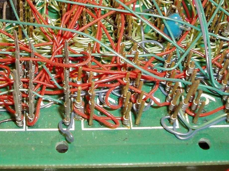
Control boards in household appliances are usually simple and low-tech - their printed base is single-layer, with one of the sides does not have a metallization and a mask. The simplicity of these boards is determined by the final price of the devices themselves - the more difficult the production of equipment is, the more expensive it will be to sell. It is clear that the mass consumer will not want and will not overpay for complications.

Typical representative of a home appliance control board
During the work we have several standard wireless modules from RM2 to RM10. These modules, based on the SoC solution, perform the role of a central controller, and also allow the device to be controlled by air.
This line of wireless modules is designed to be able to be installed on the control board, minimally changing it. To ensure high speed of development, there is an urgent need to make a debugging board, in which there will already be everything that is necessary for smart home appliances.
Another argument for the release of the debug board was the opening of the Ready for Sky platform for third-party developers. We began to receive offers and requests to e-mail to give access to the platform to independent developers or DIY developers. A similar proposal came even in Habrovskaya PM.
Debugging
So we did it - the first version of RFS-DEV001. The heart of the debug board is the RM10 module. Based on the nRF52832 chip, which complies with the Bluetooth 5 standard, it supports mesh networks and Bluetooth Low Energy. Also on debugging, a real-time clock is placed; three power options are implemented (battery, USB from PC, external from power source). Two buttons, a buzzer and an RGB diode to signal and blink. All components on the board are selected from those that are now used in the mass production of household appliances.
In addition to working out the control scheme, the developer will be able to immediately determine and optimize the cost of components, which ultimately will affect the price of his smart device.

The fee will be convenient for DIY-users, among whom there are those whose programming is not a strong point or they are just beginning to learn. We saw an opportunity to facilitate their work, for example, to make the Arduino-compatible board. It is clear that this is an amateur and educational format, but its use, firstly, does not negate professional work with debugging, and secondly, greatly enhances the convenience of professionals entering the profession.
It would be quite possible to distribute fees among universities and specialized technical schools for teaching undergraduate students, thereby contributing to future specialists.
List of guaranteed working plugins
- Atmospheric pressure and temperature sensor BMP180
- Atmospheric pressure and temperature sensor BMP280
- Moisture sensor
- IR sensor
- MQ-135 gas sensor
- MQ-9 gas sensor
- Motion Sensor HC-SR505
- Motion Sensor HC-SR04
- Tilt Sensor SW-520D
- Accelerometer, MPU9250 Magnetometer
- Accelerometer, Magnetometer GY-85
- Light sensor and proximity AP3216
- GY-2561 light intensity sensor
- Gesture Recognition Module APDS-9960
- Stepper Motor Control Module Arduino Motor Shield
- Module to connect extra. USB Arduino USB Host Shield
- Arduino 4 Relays Shield Relay Module
- Wireless SD Card Module
- GSM (GPRS) module SIM900
- LC12S Transceiver
- 433/868 MHz NRF905 Module
- IR module XY-MK-5V
- RFID / NFC-module PN532
- Display
- Display
- GPS module MIKROE-1032 GPS Click
- GLONASS module MIKROE-1895 GNSS3
- Keyboard module 4x4 MIKROE-86
- Diode matrix MIKROE-1881
- Adafruit NeoPixel Shield for Arduino diode matrix
- At the same time, we plan to release our modules, also on the basis of components used in mass production. If you have any ideas or suggestions, write in the comments what modules you might need.

API
Since debugging without software code will become a low-use piece of PCB, it’s worthwhile to tell a little about the API, which is intended to allow a developer to concentrate on the functionality of his device, apart from numerous Bluetooth settings, etc., as part of the opening platform.
So, API R4S consists of:
- a set of libraries providing the work of typical and specific services, for example, the main library containing the basic Bluetooth settings and libraries focused on the functionality of devices;
- examples of devices or functions implemented on the API;
- drivers for peripherals connected to the debug board, see the list above.
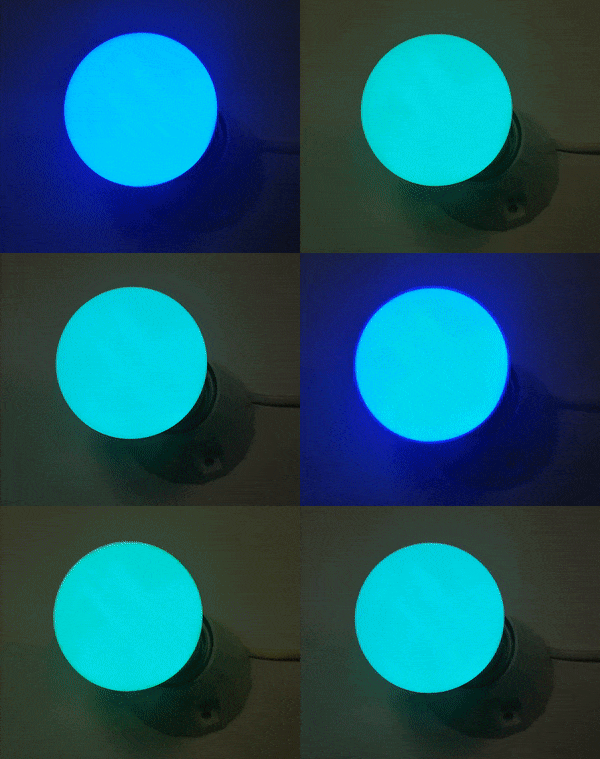
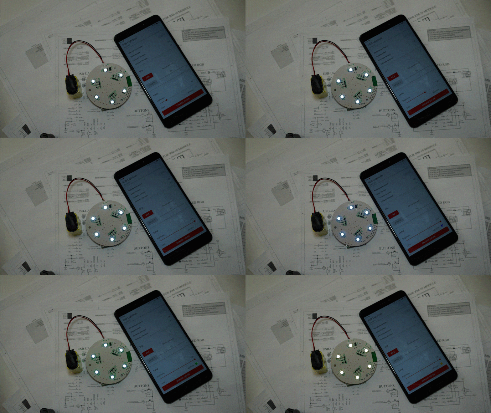
You can slightly consider the possibilities of the API on the example of creating light effects using an LED lamp through a smooth change in brightness using Bezier curves.

Turning to peyring mode, the light bulb will gradually change the color of the glow.
In the main file, you will need to independently determine basic information, for example, information about the firmware, declare settings (location of the bootloader, buffer for updating the firmware, etc.).
/** Firmware information structure */ R4S_FW_INFO_DEF(application, 0x26000) = { .version = { .major = 0, /** Product version (major) */ .minor = 1, /** Product version (minor) */ }, .name = { /** Device name */ .name = "RGB Lightbulb", .len = sizeof("RGB Lightbulb") - 1 /** Without \0 symbol at the end*/ } }; /** The init structure with the device information wich required for ReadyForSky library. */ R4S_CONFIG_DEF(r4s_init_conf) = { .p_fw_info = &application, .production_key = NULL, /** * The production key allows integrating the device into ReadyForSky infrastructure. * Contact support to get the production key for your device. */ .bootloader = { .start_address = 0x7B000, /** Bootloader start address */ .mbr_param_page = 0x7f000, /** MBR param page address */ .fw_upgrade_buf = { /** The firmware upgrade buffer is used for background flashing. * The region size should more than softdevice + bootloader + application size + 4096 */ .p_api = &nrf_fstorage_sd, /** fstorage api */ .start_addr = 0x35000, /** start address of firmware upgrade buffer */ .end_addr = 0x78000, /** end address of firmware upgrade buffer */ .chunk_size = 0, /** default chunk size */ } }, .company_info = { .p_company_name = "Imperium of Mankind", }, .watchdog = { .timeout_ms = 5000, /** If loop or priority will not finish after 5 seconds watchdog will reset microcontroller automatically */ }, .low_power_mode_enable = true, /** Low power ble settings */ } The development of the device is similar to the development under the Arduino. There is a setup function to initialize the main modules and the loop where the processing takes place. The application functionality itself is divided into modules - according to different operations performed.
/** @brief Application initialisation * @return none */ void app_setup(void) { m_pairing_init(m_led_ctrl_pairing_handler); m_led_ctrl_init(); } /** @brief Application loop * @return true - sleep is not allowed * @return false - All modules have completed operation, the mcu can enter into sleep mode. (the next loop iteration will be after any interrupt) */ bool app_loop(void) { return NRF_LOG_PROCESS(); } After the resources are declared in the file (“m_resources.c”) - for example, light bulb animations, pin assignments (several LED groups), colors, etc., the library itself will determine the remaining parameters.
/** Animation timer definition for m_rgb */ APP_TIMER_DEF(animation_timer_id); /** Leds pin map for m_rgb*/ static const r4s_rgb_ctrl_led_t m_leds_map[LEDS_COUNT] = { { .color = { .red_pin = RED_LEDS_0_PIN, .green_pin = GREEN_LEDS_0_PIN, .blue_pin = BLUE_LEDS_0_PIN, } }, { .color = { .red_pin = RED_LEDS_1_PIN, .green_pin = GREEN_LEDS_1_PIN, .blue_pin = BLUE_LEDS_1_PIN, } }, { .color = { .red_pin = RED_LEDS_2_PIN, .green_pin = GREEN_LEDS_2_PIN, .blue_pin = BLUE_LEDS_2_PIN, } }, }; /** PWM map for m_rgb */ static const r4s_rgb_ctrl_pwm_map_elem_t m_pwm_map[LEDS_COUNT] = { { .color = { .p_pwm_red = &pwm0, .p_pwm_green = &pwm0, .p_pwm_blue = &pwm0, } }, { .color = { .p_pwm_red = &pwm1, .p_pwm_green = &pwm1, .p_pwm_blue = &pwm1, } }, { .color = { .p_pwm_red = &pwm2, .p_pwm_green = &pwm2, .p_pwm_blue = &pwm2, } }, }; /** RGB lamp definition */ R4S_RGB_CTRL_DEF(m_rgb, m_leds_map, m_pwm_map, &animation_timer_id, LEDS_COUNT, 3); After bonding, the application receives data that the device can do, a light bulb in our case, and displays the corresponding information.

Further, through the application, you can control the parameters - intensity, color, temperature, etc.

Now the code is being worked out on a debugging prototype, so let the difference between the board and the upper images does not bother you.
Additional features include:
- Multiconne - several smartphones simultaneously connected to the module. Potentially, this function causes problems when trying to simultaneously control the device. We have tried to preempt these problems, including through notifications on all connected smartphones - when a parameter is changed by one phone, information about the new value of the parameter will be immediately sent to the rest;
- Fast flashing - the size of the packet transmitted via Bluetooth depends on the MTU . As the MTU increases, the flashing process will go faster as the packet size increases;
- The list of typical errors determined by the function of the microcontroller. When an error is detected, a text like “Not enough memory for softdevice. For more information enable sdm debug. ”.
To work with debugging, the engineering application R4S will be released with the same capabilities as the usual one, but it is through it that the board is managed. In principle, through the engineering application, you can manage the assembled devices in your apartment - a nice piece for DIY. This should help in device support for novice developers. In the main R4S application, such a device will appear after coordination and quality control on our part.
We will also use debugging in the daily work of the company, including in training new employees. Habrovchane, as you think, take off? Would you be interested in working with such debugging?
Source: https://habr.com/ru/post/429822/
All Articles