Analog indicator of computer load
I once met a post from ClusterM where he made a widget in the form of old indicators. I really liked this idea because there is a pleasant feeling of vintage in this project. But here's a bad luck - I have never worked with the microcontroller myself and I program so-so, so I postponed the idea for a long time. But recently, I came across a video where Alex finalized the program with the help of his acquaintances, Open Source, and developed an algorithm for processing data from Arduino. In this article I want to show how I implemented this task.
Stage I. How I figured out with the download monitor code

After downloading the monitoring program, I connected the arduino with the display, into which the code from the examples library analogRead was sewn up, it simply displays everything that the arduino receives at the com port. As you can see, I received an array of characters, at first I tried to understand experimentally, but then spat I decided to enter more professionally and opened the source provided with a code reader. With the help I found the part that sends all the data as an array, for my convenience I wrote them out on a piece of paper, since Alex did not change the code with Alex’s team, I just took the values of the processor, video card, and RAM, these are PCdata [ 4], PCdata [5], PCdata [6]. After that, I could continue to work only with Arduino.
Stage II. Understanding data parsing and processing
Honestly, I would not say that I figured out, in the style of the beginner geek, I just realized that I needed the code written by Alex without any modifications, so I added it to my code. Parsing looks like this:
while (Serial.available() > 0) { char aChar = Serial.read(); if (aChar != 'E') { inData[index] = aChar; index++; inData[index] = '\0'; } else { char *p = inData; char *str; index = 0; String value = ""; while ((str = strtok_r(p, ";", &p)) != NULL) { string_convert = str; PCdata[index] = string_convert.toInt(); index++; } index = 0; isDataExist = true; } } } For greater certainty, through the lcd.Write command, I alternately output PCdata values [4] to make sure that I accept the data that I need.
Then I took up the transfer of data as a percentage in our signal. Knowing that the signal is from 0 to 255, and we take values from 0 to 100 (this is a percentage load) using the map function and limiting values using the constrain function, I write simple code:
cpu = map(cpu, 0, 100, 0, 255); cpu = constrain(cpu, 0, 255); analogWrite(9, cpu); gpu= PCdata[5]; gpu = map(gpu, 0, 100, 0, 255); gpu = constrain(gpu, 0, 255); analogWrite(3, gpu); mem= PCdata[6]; mem = map(mem, 0, 100, 0, 255); mem = constrain(mem, 0, 255); analogWrite(5, mem); Stage III. How to connect 3 indicators to one arduino?
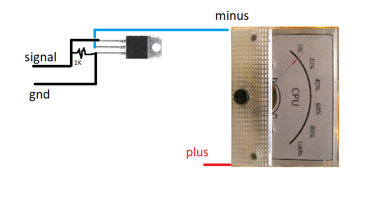
When I was just starting out - I connected only one indicator and everything is really fine, but as soon as the second appears, the problems begin. Arduino cannot “shake” the two together, I suspect that this is due to the Arduino fee, there are so many things that devouring consume energy (all sorts of LEDs, stabilizers, protection from fools, etc.) if you use Atmega itself as a ClusterM - it should be enough, for two certainly. I solved the problem with the help of mosfet transistors, I had an IRF520 on the constructor board with AliExpress, I connected one indicator through the mosfet and the second directly into Arduino and it all worked. Since the board with Ali is excessively huge, I decided to solder myself, I did not want to part the board at all, so I drew a marker on PCB.

It turned out compact, but for me this is important.
The wiring diagram is the same as for the board with Ali, well, almost, I removed the LED, so the work indication is not needed here.
Stage IV. Design backs for the indicator
Specially retained its design for publication, but I successfully lost the final sketch, but the enlarged prototype remained. Later, I realized that this is not a big problem, since I will have to adjust to the size of your indicators, I did in paint Photoshop 2020, so I am sure that you will be able to modify it.
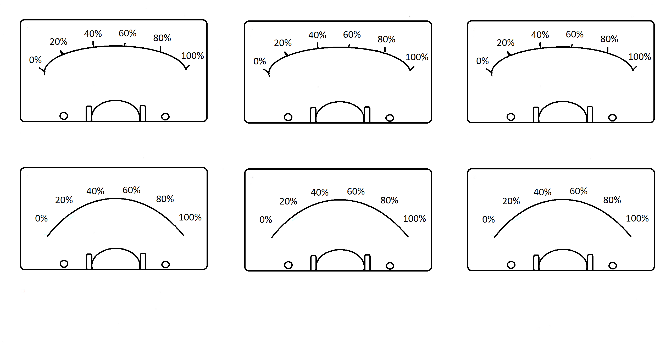
It seems to me that it came out very interesting, it remains to cut a place for screws and arrows - that's it!
Stage V. RGB backlight
Since in the process I realized that I had nowhere to cram the LED - I finally refused, but the initial code did, it is very simple - everyone can do it, just add for all the colors for the three indicators. Designed on a brainboard - works like a clock:
void led() { if (PCdata[4] < 20 ) { digitalWrite (6, HIGH);//, rgb } else{ digitalWrite (6, LOW); } if (PCdata[4] > 20 && PCdata[4] < 60 );// , // { digitalWrite(5, HIGH);// - } // } Total
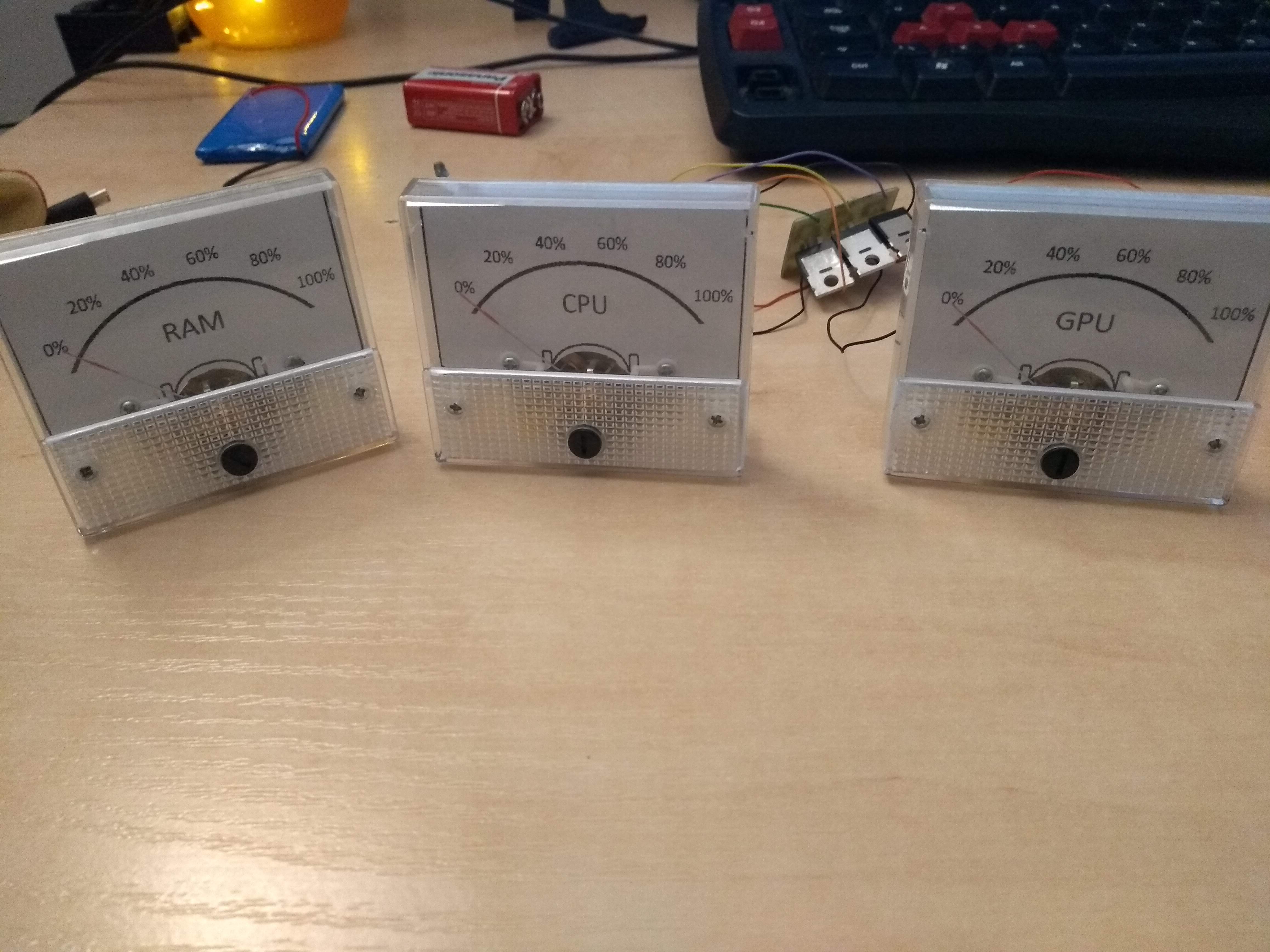
It turned out to be an interesting widget, which is useful when playing games, editing video and photos, since you can evaluate whether the computer is overloaded.
Advice - try not to drop your indicators, I accidentally fell from the RAM and the arrow does not come to zero, it is being repaired but these are creepy crutches.
Whole code for arduino
//#include <Wire.h> // //#include <LiquidCrystal.h> // , //LiquidCrystal lcd(8, 9, 4, 5, 6, 7); char inData[82]; // () int PCdata[20]; // byte index = 0; String string_convert; bool isDataExist = false; int cpu; int mem; int gpu; void setup() { Serial.begin(9600); } void loop() { parsing(); //led(); cpu = PCdata[4]; cpu = map(cpu, 0, 100, 0, 255); cpu = constrain(cpu, 0, 255); analogWrite(9, cpu); gpu= PCdata[5]; gpu = map(gpu, 0, 100, 0, 255); gpu = constrain(gpu, 0, 255); analogWrite(3, gpu); mem= PCdata[6]; mem = map(mem, 0, 100, 0, 255); mem = constrain(mem, 0, 255); analogWrite(5, mem); } void parsing() { while (Serial.available() > 0) { char aChar = Serial.read(); if (aChar != 'E') { inData[index] = aChar; index++; inData[index] = '\0'; } else { char *p = inData; char *str; index = 0; String value = ""; while ((str = strtok_r(p, ";", &p)) != NULL) { string_convert = str; PCdata[index] = string_convert.toInt(); index++; } index = 0; isDataExist = true; } } } /*void led() { if (PCdata[4] < 20 ) { digitalWrite (6, HIGH);// rgb } else{ digitalWrite (6, LOW); } if (PCdata[4] > 20 && PCdata[4] < 60 );// , , { digitalWrite(5, HIGH);// - } // } */ The monitoring program is in the archives of Alex
I used the old version, it works great, so I advise you.
I would like to thank Alex and his team for the refinement of the Open Source code, as well as to the ClusterM user for demonstrating his gadget and my dad for helping to decipher the code.
')
Source: https://habr.com/ru/post/429582/
All Articles