Home power network
Here, the topic of protection of equipment in the home power supply network often arises, but the information is not very true when describing the basic parameters of protection devices or, at best, based on individual examples. Therefore, further there will be a kind of educational program on how to properly make an introductory electrical panel.
This is not so much an instruction as an explanation of what needs to be done, since each connection is essentially individual. In any case, consultation is necessary considering the real situation.
In the future, I will assume that the electricity supplier performs its work as it should, therefore the voltage remains within the limits prescribed by the norms.
I will proceed from the mains voltage of 230/400 V (the second is important to know when a three-phase input). Most consumers are single-phase, exceptions can be electric cookers and electric motors of pumps.
')
All the usual automatic circuit breakers (hereinafter simply automatic).
Automata with time-current curves B and C are used in apartments. In fact, there are many of them and for different purposes. In this document on the third page there is a schedule where you can see the differences . Vertical time, horizontal - current.
But we will focus on the B and C machines, as the most frequent and applicable both in industry and at home.
Each switch has two categories of two main indicators according to international standards:
Categories:
Indicator:
In general, these values are as follows for overloading after 1 hour (triggered by thermal energy) for automatic machines of types B or C at an ambient temperature of 30 degrees:
Maximum failure current = 1.13 rated current
The minimum guaranteed operation current = 1.45 rated current
With increasing temperatures, these numbers become smaller, but according to the norms, the non-operation should not be less than the rated current at an ambient temperature of 50 degrees. Almost all manufacturers specify these figures in the catalogs and they can vary greatly.
For a short circuit, these values differ for switches (so-called electromagnetic actuation without delay):
Type B - 3 * In and 5 * In
type C - 5 * In and 10 * In
Although this is called “triggering without delay”, the norms guarantee triggering up to 0.1 second, not more. In fact, this time is 0.05-0.07 seconds.
What happens between the boundary currents - no one can guarantee and will not, according to the norms, the shutdown can last from 0.1 to 15 seconds (for C-automata). Although, in principle, the switch may operate immediately from the minimum value or not operate for a full 15 seconds to the maximum. And when choosing switches, you need to remember this.
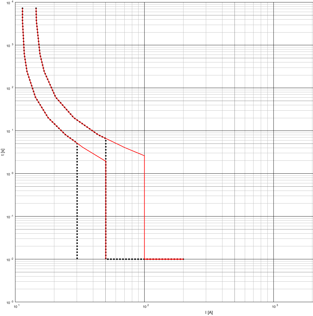
The example below is the time-current characteristics for B and C switches at 10A from Siemens. 10A is selected for ease of comparison. B - black color, C - red.
Previously - the only and very widely used device for residential premises, now much less. The most common in the mains - cork and knife fuses. Today, there are combined fuse-disconnectors, which differ from circuit breakers in that, when triggered, it is necessary to install new fuses before reconnecting.
One of the devices, which, despite the age of technology, still offers some very useful properties.
The main advantage is guaranteed operation in case of a short circuit. The main drawback is disposability.
Why are fuses still being used? First, the price. They are much cheaper than circuit breakers because they do not have mechanical parts. Secondly, in the case of a sufficiently high value of short current (for a 10A fuse - more than 210 A), the response speed will be less than 0.01 second, less than half of the alternating current period (no other switch operates so quickly). Thirdly, they can be very simple and guaranteed to be selectively built (about selectivity below). This article deals with general purpose fuses, which are denoted by gG (also previously gL - line protection).
In this case, there are no manufacturers who make fuses in accordance with the rules in terms of time to turn off, they are always better than foreseen. But each has its own best.
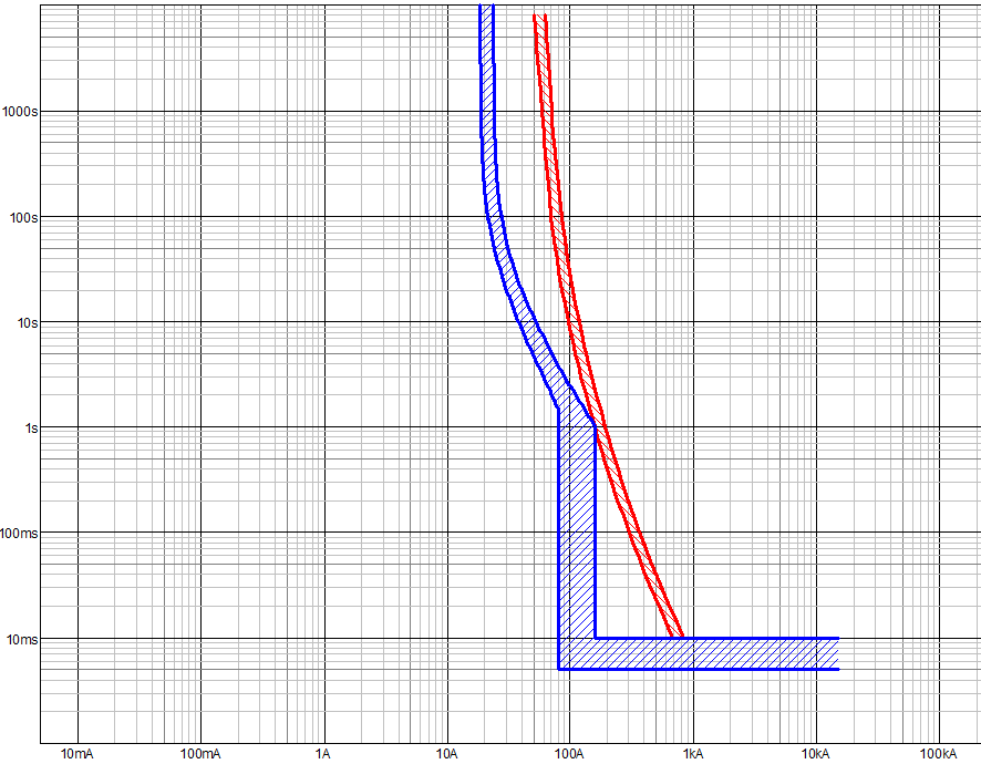
Below is a comparison of the characteristics according to the norms and measurements from the ABB for a fuse of 10 A. It should be noted that the norms provide for characteristics from 0.01 seconds, but since for this time only extrapolations are possible in principle, not every program has these graphs. Black - according to the norms, red - produced by ABB.

There is always the possibility of leakage currents, especially in wet areas. Therefore, a device was created that captures this current, which is called a differential current device or UDT (the designation according to the new GOST standards-translations of the IEC standards, also known as RCD, is a protective shutdown device). The idea is simple - the device compares the current in the phase and the neutral wire, if they are equal - everything is fine, if not, then a trip is made. There are a number of devices that can be used at home, with currents of 10 mA, 30 mA, 100 mA, 300 mA and different types - AC, A, F, B, B +. The speaker type is triggered only by sinusoidal leakage currents, type A may, in addition to the speaker type, trigger pulsating direct currents and so on. It is recommended to install type B, as it works on all possible types of leakage. Type B + in its essence assumes part of the arc protection functions. Today, UDTs with currents up to 30 mA serve to protect people, from 100 and above, to protect equipment, although there used to be UDT 500 mA for installation in apartments.
Do not forget, for different currents in UDT different sensitivity. For example, the above 30 mA means the upper limit of operation for AC leakage, in fact, the operation can occur at rates between 15 and 30 mA (manufacturers here try to go to shutdown up to 25 mA, as the upper limit). If we take a pulsating direct current, then there will already be a trigger between 12 and 42 mA.
Why is it important? The leakage current exists almost always, for example in a socket or in an electrical appliance. It is believed that a 30 mA ultrasound can be applied before a maximum of 10 sockets, otherwise there will be a shutdown in normal mode. Or the length of the wire plays a role. In particular, there are such values for leakage current per 100 meters of wire (wire from the phase, neutral wire and earth):
1.5 mm² - 4.8 mA
2.5 mm² - 5.6 mA
4.0 mm² - 6.6 mA
Therefore, when planning it is important to take into account the length of cables and the distribution of the rooms.
As it is often used as a circuit breaker, and UDT, there are combined devices - differential automata, two in one. According to the new regulations in Germany since 2018, their use has been recommended for residential premises in order to save space and simplify distribution boards.
What should be remembered - the device requires checks. At least once every 6 months, the operation should be checked using the button on the device. Naturally, this is not a test for tripping by leakage currents, but many people even forget about this. The operation of leakage currents requires a special device, which is switched on by the UDT, and can produce a test with various types of current.
When a lightning strike near the cable, an electromagnetic wave arises, which can literally destroy the devices connected to the network. Therefore, the use of surge protective devices (surge protective device, SPD) is recommended.
At its core, this is an arrester implementation for low voltages. The idea is to use special materials that do not conduct current at normal voltage (in theory, in practice there is leakage current), and when a certain level is exceeded, they become conductors. The protective function is to reflect the wave, because the device protects both before and after itself (the effective distance is about 10 meters of cable).
There are three types of devices:
The first type is lightning protection, sometimes equipped with a small discharger. Must be necessarily grounded to the main ground bus for the discharge of excess energy. As a result of operation, the voltage must not exceed 6 kV.
The second type is medium overvoltage protection. As a result of protection, the voltage should not exceed 4 kV
The third type is device protection. Voltage less than 1.5 kV as a result of protection.
In the absence of the first type, the installation of further devices is meaningless, since the wave energy is too high for type 2. Also, the devices installed in cascade must be coordinated with each other (usually means from one manufacturer, as there are differences in characteristics).
The cable between the grounding output of the device and the grounding bus or (in the case of types 2 and 3) PE must not exceed 50 cm.
There are combined devices from several types in one, like 1 + 2 or 2 + 3.
The idea of the device is that, for example, when insulation is damaged, arcing arises, which only later develops into a ground fault or a short circuit. This is not recognized by the above devices. Relatively new devices in Europe and not yet widespread.
Today, these devices are recommended for use in hazardous areas, as well as where there are many children or the elderly. In other cases, the device is optional.
Since I have not applied them in my practice so far, unfortunately I cannot describe them in more detail.
The devices have been described above, now more detailed about how to connect them correctly. The essence of selectivity - the protective device closest to the place of a short circuit / overload should turn off. Almost always this is possible for equipment in residential premises, but in some cases (for example, a very high short-circuit current) cannot be guaranteed. Then there will be a couple of examples divided into groups.
Everything is relatively simple here. Fuses from 16A and above with a rated current ratio of 1.6 are selective. For example, for a fuse 25A: 25 * 1.6 = 40A. In the case of 40A, this is a fuse 63A, although 40 * 1.6 = 64, since the closest ones by the nominal row are selected. Although fuses from one manufacturer may have a lower ratio, but 1.6 is a guaranteed ratio for any manufacturer.
For fuses less than 16 A, this ratio is different and may be 1.9 (in the case of Germany). Those. for fuse 10A, selective is 20A, not 16A. At the same time, many manufacturers produce fuses with a ratio of less than 1.6, but only for their own production and there is no guarantee of compatibility, for example, between ABB and Siemens in this case.
Theoretically, if the characteristics do not overlap, the switches can be considered selective. In practice, this can only be true for switches of the same manufacturer and, then, use the selectivity tables. They indicate either the total selectivity or the boundary current to which the selectivity is guaranteed. If the latter is exceeded, any of the switches may be triggered, in the case of a certain distance between the switches (not in one panel), the probability of the switch from the supply side is greater.
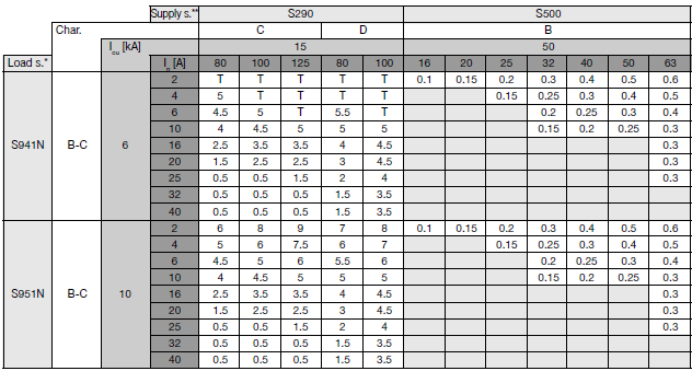
Below is an example of such a table for ABB switches. The letter T means total (“total”) selectivity, the numbers represent the maximum current in kiloamps.
There are also selective switches. They are triggered with a deceleration during a short circuit, giving the opportunity to first operate below the located switches. With a sufficiently large current, as in the example above, may work earlier.
Here the situation as a whole is more complicated and maybe, in the case of relatively large currents, it is determined only by tables, such as this, with equipment from Siemens.
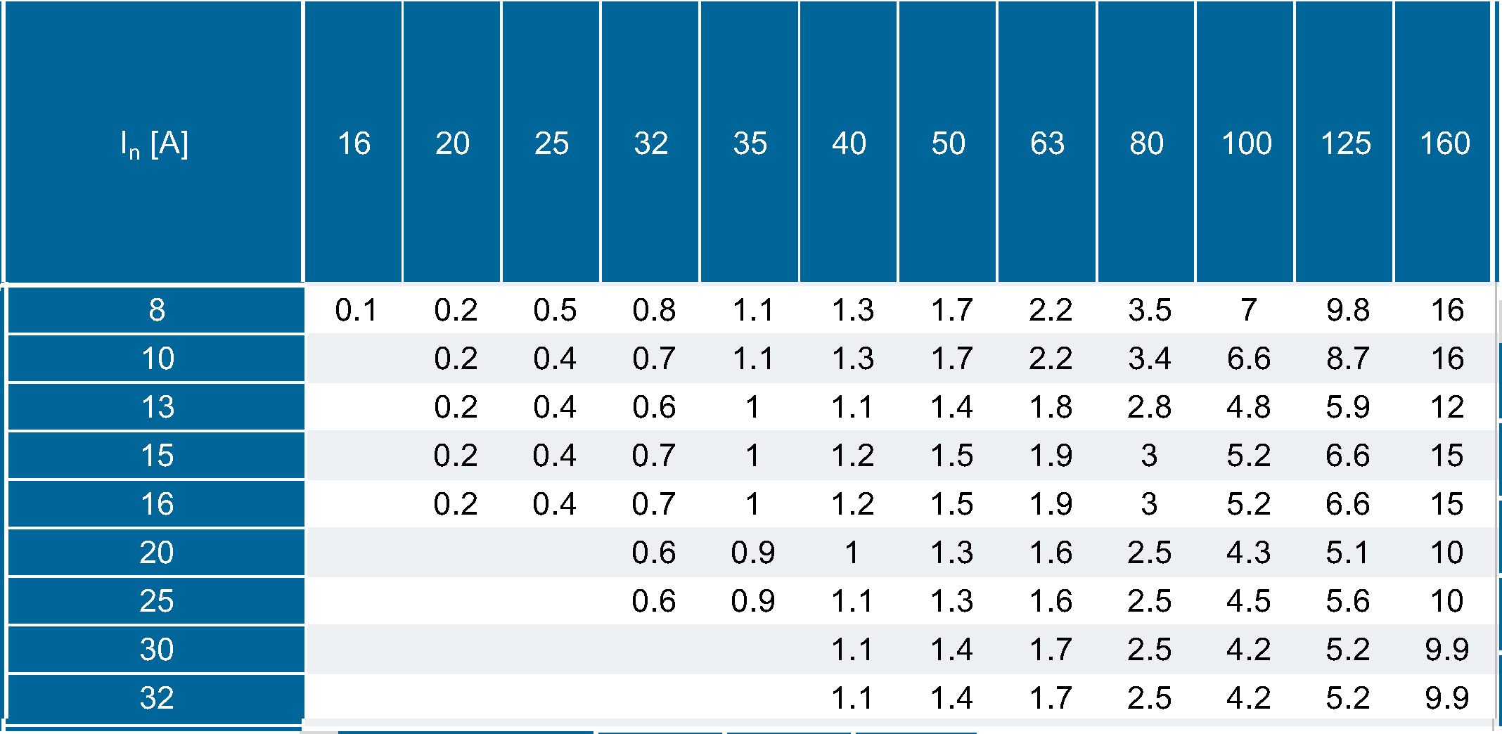
Here, only a part of the table was shown, in which the switches are compared with the characteristic C (vertical numbers) of Siemens fuses.
For example, the characteristics of the S16A circuit breaker and 40A fuse from Siemens look like

The same components, but from ABB
Unfortunately, the sources are different programs, so it was not possible to make the scale the same for comparison.
Naturally, if in the above case, the short-circuit currents in the region of 160-300 A, then even without tables, it is clear that the switch will be the first to operate. But now at 500 And without tables, no one can guarantee this.
In all the above cases, it is possible to conduct your own analysis. To do this, you need to find graphs of current limiting and transmitted energy devices. Comparing them you can make certain assumptions. Unfortunately, for guaranteed compatibility, the switches should come with a large margin. This is one of the advantages of fuses - the above ratio of 1.6 gives a guaranteed selectivity in most situations.
In the case of switches in home use, it should be selected at the nominal value or as recommended by the equipment manufacturer. In any case, it should be remembered that the actuation of thermal energy depends on the temperature of the medium in which the switch is located.
For fuses, the manufacturer often indicates that, for a long time, no more than 90% of the rated current. Depends on the manufacturer.
With long-term operation of the switches and fuses, they heat up and, accordingly, heat each other. Because there are additional correction factors that take into account both the number and location of switches. The table data should also be taken according to the manufacturer.
By the way, not everyone knows that ordinary home sockets for 16A, like “shuko”, are tested with a maximum current of 16A for only one hour and should not be hotter than 70 ° C. What happens after this period - no one guarantees. Therefore, the recommended long-term load is not more than 13A. As an option, it is possible to use industrial sockets, the same 16A there, but they can be calculated for 6 and 12 hours.
When choosing a device, you should not forget that some devices have starting currents. In particular, the indoor unit of the air conditioner can have a small current in the normal mode, 0.2-0.4A, but here the inrush currents can reach 18 times.
UDT for most cases, 30 mA is sufficient. For wet rooms in recent times put 10 mA. It all depends on the length of the network. You can also install a selective UDT on the power panel. Their current sensitivity is worse (100 or 300 mA) and this is more an auxiliary device in case of failure of one of the downstream. The main thing is to take the same or worse type by properties; selective UDT with type B before type A is not allowed.
How to determine the short-circuit currents? Alas, only to measure. Even in a new house, the cable length may differ from the design one, the cable resistance obeys even the best manufacturer to normal distribution, there may be changes at the transformer substation, therefore even the network operator can only give approximate values. There are special devices that serve to measure single-phase short circuit current. If at the moment there is only a shield or a connection point, then the current short to the outlet can be calculated by simple Ohm's law, although ideally it is worth trying the measurement.
The regulations provide for short circuit tripping for TN systems within 0.4 seconds and for TT systems - within 0.2 seconds. Here it should be remembered that for a circuit breaker the relevant standards in this case is the current shutdown is longer than the guaranteed electromagnetic response time (10 times or more of the rated current for the C-switch and 5 or more for the B-switches). But for fuses, this value is determined by the characteristics of the time-current.
It all depends on which system is powered.
Grounding is done at the house and the protective wire has no connection to the supply network. The transformer somewhere there far has its own grounding. In this case, the neutral disconnection is necessary, since its potential will differ from the building potential even with a symmetrical load.
TN-C option
Protective conductor and neutral in one cable. In this case, the disconnection of the neutral wire (PEN in this case) is prohibited, since it performs a protective function.
TN-CS option
In this case, when the power was supplied to the house, the PEN wire was divided into N and PE. Disabling N is acceptable, but disabling PEN is not. To equalize possible potential differences, PEN may be connected to the building grounding. In the case of close proximity to a substation, this may not be the case.
TN-S option
N and PE are brought into the house separately. It is also possible to disable N.
More details about the grounding system can be found here.
Naturally, the desire to save and, for example, install one UDT on several switches. It is important to note here that later it will be more difficult to find the place of operation and the leakage currents of the connected equipment may exceed the threshold of sensitivity of the device.
The topic of discussion is the order of connection - what to put at the beginning, UDT or switch / fuse? There is no unambiguous answer, I have often met the UDT in practice before the switch or fuse, with the advent of the combined device this question can be ignored.
Circuit breakers and fuses are used to protect lines and are calculated only up to the outlet. What will be included later is not obliged to defend them.
The wire must withstand higher currents than the device protecting it. Since there are now a huge number of different types of wires, when choosing, one should be guided by the manufacturer’s data regarding short-circuit currents and long-lasting currents, but there are a couple of points about them further.
In these data you can find beautiful numbers, such as the permissible continuous current for a wire with PVC insulation of 3x1.5 mm² at 27 A. It would seem that if you take the C-automat on 16 A, it will still turn off the line at 23.2 A at the latest. But this value is for laying in the wall or in the ground. If you look at the data for laying in the air or pipe, then there will be only 19 A. And then there are still a number of factors, like the presence of adjacent wires. For example, if there are 2 other wires nearby, which are simultaneously loaded, then the permissible current will be 13.3 A - here even the C-10A automat cannot be used.
As for the values of short-circuit currents, as a rule, a current is given that is maintained for a time of 1 second. To convert to other values (up to 5 seconds), you can use the following formula:
A series of articles about grounding from arozhankov
Schneider Electric online electrical installation guide . True, I advise the English or German version, they are much more complete.
The continuation of this article with the calculations
This is not so much an instruction as an explanation of what needs to be done, since each connection is essentially individual. In any case, consultation is necessary considering the real situation.
Introduction
In the future, I will assume that the electricity supplier performs its work as it should, therefore the voltage remains within the limits prescribed by the norms.
I will proceed from the mains voltage of 230/400 V (the second is important to know when a three-phase input). Most consumers are single-phase, exceptions can be electric cookers and electric motors of pumps.
')
Equipment
Circuit breaker
All the usual automatic circuit breakers (hereinafter simply automatic).
Automata with time-current curves B and C are used in apartments. In fact, there are many of them and for different purposes. In this document on the third page there is a schedule where you can see the differences . Vertical time, horizontal - current.
But we will focus on the B and C machines, as the most frequent and applicable both in industry and at home.
Each switch has two categories of two main indicators according to international standards:
Categories:
- Overload current
- Short circuit current
Indicator:
- Maximum current failure
- The minimum current guaranteed operation
In general, these values are as follows for overloading after 1 hour (triggered by thermal energy) for automatic machines of types B or C at an ambient temperature of 30 degrees:
Maximum failure current = 1.13 rated current
The minimum guaranteed operation current = 1.45 rated current
With increasing temperatures, these numbers become smaller, but according to the norms, the non-operation should not be less than the rated current at an ambient temperature of 50 degrees. Almost all manufacturers specify these figures in the catalogs and they can vary greatly.
For a short circuit, these values differ for switches (so-called electromagnetic actuation without delay):
Type B - 3 * In and 5 * In
type C - 5 * In and 10 * In
Although this is called “triggering without delay”, the norms guarantee triggering up to 0.1 second, not more. In fact, this time is 0.05-0.07 seconds.
What happens between the boundary currents - no one can guarantee and will not, according to the norms, the shutdown can last from 0.1 to 15 seconds (for C-automata). Although, in principle, the switch may operate immediately from the minimum value or not operate for a full 15 seconds to the maximum. And when choosing switches, you need to remember this.
The example below is the time-current characteristics for B and C switches at 10A from Siemens. 10A is selected for ease of comparison. B - black color, C - red.
Fuse
Previously - the only and very widely used device for residential premises, now much less. The most common in the mains - cork and knife fuses. Today, there are combined fuse-disconnectors, which differ from circuit breakers in that, when triggered, it is necessary to install new fuses before reconnecting.
One of the devices, which, despite the age of technology, still offers some very useful properties.
The main advantage is guaranteed operation in case of a short circuit. The main drawback is disposability.
Why are fuses still being used? First, the price. They are much cheaper than circuit breakers because they do not have mechanical parts. Secondly, in the case of a sufficiently high value of short current (for a 10A fuse - more than 210 A), the response speed will be less than 0.01 second, less than half of the alternating current period (no other switch operates so quickly). Thirdly, they can be very simple and guaranteed to be selectively built (about selectivity below). This article deals with general purpose fuses, which are denoted by gG (also previously gL - line protection).
In this case, there are no manufacturers who make fuses in accordance with the rules in terms of time to turn off, they are always better than foreseen. But each has its own best.
Below is a comparison of the characteristics according to the norms and measurements from the ABB for a fuse of 10 A. It should be noted that the norms provide for characteristics from 0.01 seconds, but since for this time only extrapolations are possible in principle, not every program has these graphs. Black - according to the norms, red - produced by ABB.
Differential current device
There is always the possibility of leakage currents, especially in wet areas. Therefore, a device was created that captures this current, which is called a differential current device or UDT (the designation according to the new GOST standards-translations of the IEC standards, also known as RCD, is a protective shutdown device). The idea is simple - the device compares the current in the phase and the neutral wire, if they are equal - everything is fine, if not, then a trip is made. There are a number of devices that can be used at home, with currents of 10 mA, 30 mA, 100 mA, 300 mA and different types - AC, A, F, B, B +. The speaker type is triggered only by sinusoidal leakage currents, type A may, in addition to the speaker type, trigger pulsating direct currents and so on. It is recommended to install type B, as it works on all possible types of leakage. Type B + in its essence assumes part of the arc protection functions. Today, UDTs with currents up to 30 mA serve to protect people, from 100 and above, to protect equipment, although there used to be UDT 500 mA for installation in apartments.
Do not forget, for different currents in UDT different sensitivity. For example, the above 30 mA means the upper limit of operation for AC leakage, in fact, the operation can occur at rates between 15 and 30 mA (manufacturers here try to go to shutdown up to 25 mA, as the upper limit). If we take a pulsating direct current, then there will already be a trigger between 12 and 42 mA.
Why is it important? The leakage current exists almost always, for example in a socket or in an electrical appliance. It is believed that a 30 mA ultrasound can be applied before a maximum of 10 sockets, otherwise there will be a shutdown in normal mode. Or the length of the wire plays a role. In particular, there are such values for leakage current per 100 meters of wire (wire from the phase, neutral wire and earth):
1.5 mm² - 4.8 mA
2.5 mm² - 5.6 mA
4.0 mm² - 6.6 mA
Therefore, when planning it is important to take into account the length of cables and the distribution of the rooms.
As it is often used as a circuit breaker, and UDT, there are combined devices - differential automata, two in one. According to the new regulations in Germany since 2018, their use has been recommended for residential premises in order to save space and simplify distribution boards.
What should be remembered - the device requires checks. At least once every 6 months, the operation should be checked using the button on the device. Naturally, this is not a test for tripping by leakage currents, but many people even forget about this. The operation of leakage currents requires a special device, which is switched on by the UDT, and can produce a test with various types of current.
Surge Protection Device
When a lightning strike near the cable, an electromagnetic wave arises, which can literally destroy the devices connected to the network. Therefore, the use of surge protective devices (surge protective device, SPD) is recommended.
At its core, this is an arrester implementation for low voltages. The idea is to use special materials that do not conduct current at normal voltage (in theory, in practice there is leakage current), and when a certain level is exceeded, they become conductors. The protective function is to reflect the wave, because the device protects both before and after itself (the effective distance is about 10 meters of cable).
There are three types of devices:
The first type is lightning protection, sometimes equipped with a small discharger. Must be necessarily grounded to the main ground bus for the discharge of excess energy. As a result of operation, the voltage must not exceed 6 kV.
The second type is medium overvoltage protection. As a result of protection, the voltage should not exceed 4 kV
The third type is device protection. Voltage less than 1.5 kV as a result of protection.
In the absence of the first type, the installation of further devices is meaningless, since the wave energy is too high for type 2. Also, the devices installed in cascade must be coordinated with each other (usually means from one manufacturer, as there are differences in characteristics).
The cable between the grounding output of the device and the grounding bus or (in the case of types 2 and 3) PE must not exceed 50 cm.
There are combined devices from several types in one, like 1 + 2 or 2 + 3.
Arc Protection Device
The idea of the device is that, for example, when insulation is damaged, arcing arises, which only later develops into a ground fault or a short circuit. This is not recognized by the above devices. Relatively new devices in Europe and not yet widespread.
Today, these devices are recommended for use in hazardous areas, as well as where there are many children or the elderly. In other cases, the device is optional.
Since I have not applied them in my practice so far, unfortunately I cannot describe them in more detail.
Selectivity
The devices have been described above, now more detailed about how to connect them correctly. The essence of selectivity - the protective device closest to the place of a short circuit / overload should turn off. Almost always this is possible for equipment in residential premises, but in some cases (for example, a very high short-circuit current) cannot be guaranteed. Then there will be a couple of examples divided into groups.
Fuses
Everything is relatively simple here. Fuses from 16A and above with a rated current ratio of 1.6 are selective. For example, for a fuse 25A: 25 * 1.6 = 40A. In the case of 40A, this is a fuse 63A, although 40 * 1.6 = 64, since the closest ones by the nominal row are selected. Although fuses from one manufacturer may have a lower ratio, but 1.6 is a guaranteed ratio for any manufacturer.
For fuses less than 16 A, this ratio is different and may be 1.9 (in the case of Germany). Those. for fuse 10A, selective is 20A, not 16A. At the same time, many manufacturers produce fuses with a ratio of less than 1.6, but only for their own production and there is no guarantee of compatibility, for example, between ABB and Siemens in this case.
Circuit breakers
Theoretically, if the characteristics do not overlap, the switches can be considered selective. In practice, this can only be true for switches of the same manufacturer and, then, use the selectivity tables. They indicate either the total selectivity or the boundary current to which the selectivity is guaranteed. If the latter is exceeded, any of the switches may be triggered, in the case of a certain distance between the switches (not in one panel), the probability of the switch from the supply side is greater.
Below is an example of such a table for ABB switches. The letter T means total (“total”) selectivity, the numbers represent the maximum current in kiloamps.
There are also selective switches. They are triggered with a deceleration during a short circuit, giving the opportunity to first operate below the located switches. With a sufficiently large current, as in the example above, may work earlier.
Fuses and Circuit Breakers
Here the situation as a whole is more complicated and maybe, in the case of relatively large currents, it is determined only by tables, such as this, with equipment from Siemens.
Here, only a part of the table was shown, in which the switches are compared with the characteristic C (vertical numbers) of Siemens fuses.
For example, the characteristics of the S16A circuit breaker and 40A fuse from Siemens look like
The same components, but from ABB
Unfortunately, the sources are different programs, so it was not possible to make the scale the same for comparison.
Naturally, if in the above case, the short-circuit currents in the region of 160-300 A, then even without tables, it is clear that the switch will be the first to operate. But now at 500 And without tables, no one can guarantee this.
Different switch manufacturers
In all the above cases, it is possible to conduct your own analysis. To do this, you need to find graphs of current limiting and transmitted energy devices. Comparing them you can make certain assumptions. Unfortunately, for guaranteed compatibility, the switches should come with a large margin. This is one of the advantages of fuses - the above ratio of 1.6 gives a guaranteed selectivity in most situations.
Parameters for selection
Consumption current
In the case of switches in home use, it should be selected at the nominal value or as recommended by the equipment manufacturer. In any case, it should be remembered that the actuation of thermal energy depends on the temperature of the medium in which the switch is located.
For fuses, the manufacturer often indicates that, for a long time, no more than 90% of the rated current. Depends on the manufacturer.
With long-term operation of the switches and fuses, they heat up and, accordingly, heat each other. Because there are additional correction factors that take into account both the number and location of switches. The table data should also be taken according to the manufacturer.
By the way, not everyone knows that ordinary home sockets for 16A, like “shuko”, are tested with a maximum current of 16A for only one hour and should not be hotter than 70 ° C. What happens after this period - no one guarantees. Therefore, the recommended long-term load is not more than 13A. As an option, it is possible to use industrial sockets, the same 16A there, but they can be calculated for 6 and 12 hours.
When choosing a device, you should not forget that some devices have starting currents. In particular, the indoor unit of the air conditioner can have a small current in the normal mode, 0.2-0.4A, but here the inrush currents can reach 18 times.
Differential current
UDT for most cases, 30 mA is sufficient. For wet rooms in recent times put 10 mA. It all depends on the length of the network. You can also install a selective UDT on the power panel. Their current sensitivity is worse (100 or 300 mA) and this is more an auxiliary device in case of failure of one of the downstream. The main thing is to take the same or worse type by properties; selective UDT with type B before type A is not allowed.
Short circuit currents
How to determine the short-circuit currents? Alas, only to measure. Even in a new house, the cable length may differ from the design one, the cable resistance obeys even the best manufacturer to normal distribution, there may be changes at the transformer substation, therefore even the network operator can only give approximate values. There are special devices that serve to measure single-phase short circuit current. If at the moment there is only a shield or a connection point, then the current short to the outlet can be calculated by simple Ohm's law, although ideally it is worth trying the measurement.
The regulations provide for short circuit tripping for TN systems within 0.4 seconds and for TT systems - within 0.2 seconds. Here it should be remembered that for a circuit breaker the relevant standards in this case is the current shutdown is longer than the guaranteed electromagnetic response time (10 times or more of the rated current for the C-switch and 5 or more for the B-switches). But for fuses, this value is determined by the characteristics of the time-current.
Do I need to disable the neutral
It all depends on which system is powered.
TT system
Grounding is done at the house and the protective wire has no connection to the supply network. The transformer somewhere there far has its own grounding. In this case, the neutral disconnection is necessary, since its potential will differ from the building potential even with a symmetrical load.
TN system
TN-C option
Protective conductor and neutral in one cable. In this case, the disconnection of the neutral wire (PEN in this case) is prohibited, since it performs a protective function.
TN-CS option
In this case, when the power was supplied to the house, the PEN wire was divided into N and PE. Disabling N is acceptable, but disabling PEN is not. To equalize possible potential differences, PEN may be connected to the building grounding. In the case of close proximity to a substation, this may not be the case.
TN-S option
N and PE are brought into the house separately. It is also possible to disable N.
More details about the grounding system can be found here.
UDT installation details
Naturally, the desire to save and, for example, install one UDT on several switches. It is important to note here that later it will be more difficult to find the place of operation and the leakage currents of the connected equipment may exceed the threshold of sensitivity of the device.
The topic of discussion is the order of connection - what to put at the beginning, UDT or switch / fuse? There is no unambiguous answer, I have often met the UDT in practice before the switch or fuse, with the advent of the combined device this question can be ignored.
What is important to remember
Circuit breakers and fuses are used to protect lines and are calculated only up to the outlet. What will be included later is not obliged to defend them.
A little about the wire
The wire must withstand higher currents than the device protecting it. Since there are now a huge number of different types of wires, when choosing, one should be guided by the manufacturer’s data regarding short-circuit currents and long-lasting currents, but there are a couple of points about them further.
In these data you can find beautiful numbers, such as the permissible continuous current for a wire with PVC insulation of 3x1.5 mm² at 27 A. It would seem that if you take the C-automat on 16 A, it will still turn off the line at 23.2 A at the latest. But this value is for laying in the wall or in the ground. If you look at the data for laying in the air or pipe, then there will be only 19 A. And then there are still a number of factors, like the presence of adjacent wires. For example, if there are 2 other wires nearby, which are simultaneously loaded, then the permissible current will be 13.3 A - here even the C-10A automat cannot be used.
As for the values of short-circuit currents, as a rule, a current is given that is maintained for a time of 1 second. To convert to other values (up to 5 seconds), you can use the following formula:

Interesting articles and links
A series of articles about grounding from arozhankov
Schneider Electric online electrical installation guide . True, I advise the English or German version, they are much more complete.
The continuation of this article with the calculations
Source: https://habr.com/ru/post/429468/
All Articles