Self-made laser installation "Lightsaber" - as it were, part 1
Greetings to all, in this article we will talk about one of my most difficult projects - a homemade installation with a copper vapor laser. I will make a reservation right away that the project was completed successfully, brought to a fully finished product and justifies the name I gave him. I consider it necessary to tell in all details how it was carried out and what had to be encountered on the way to its implementation. The history of the installation is quite long, so it will have to be divided into several parts.
And one more small disclaimer: this project was carried out because of my great love for the art of receiving laser radiation, in many respects for the process of its implementation, therefore I will ask not to ask the question “why is this necessary” in the comments. The information presented is shown for informational purposes only; the author is not responsible for the consequences of attempts to repeat the above.
Picture to attract attention.
')
A sequel - under the cut.
First you have to make some lyrical digression. The thing is, I am probably one of those many people who once dreamed of their lightsaber or laser gun, at least in the form in which this is possible with current technologies. And as it turned out, everything is possible, if you work on it. From the beginning of my student days, I became interested in electrical engineering, namely, the receipt of high voltages and high frequencies. So I discovered for myself such an interesting device as a Tesla transformer in its many manifestations using a variety of topologies and the most varied element base. At the same time, I realized that I was particularly attracted to the aesthetics of the diesel engine, namely, I wanted all my products to look like they came to me straight from the laboratories of Frankenstein or Tesla himself. That is why I used the element base consisting of old oil transformers, powerful radio tubes, high-frequency motor-generators (umformers), metering panel devices in a carbolite case and so on. Nevertheless, it turned out that it is already difficult to surprise anyone even with a rather long discharge from a Tesla transformer. Therefore, I decided to change the direction of activity, occupying the niche in which very few people ventured to get into. Namely - to devote his hobby to laser technology. My dream has always been to figure out what lasers are, to reveal the secrets of their device and work, and finally to build their own coherent radiation generator. As time went on, I studied a lot of literature, communicated with different people, gradually accumulated experience in the study, tuning and repair of lasers in laboratories and produced "swag" in the form of whole lasers and their fragments, which I studied in great detail.
Among the variety of lasers, one of them deserves much more attention than the others - a copper vapor laser. When I was able to see and touch such a laser at work in one of the laboratories, he created the most powerful impressions for me. And the thing is this. This is the most effective laser operating in the visible range of the spectrum, capable of having a radiation power of tens of watts at wavelengths of 510 nm (bright green) and 578 nm (saturated yellow). The beam containing both lines of radiation has a unique greenish-lemon color and is capable of burning various combustible materials just as well as an infrared CO2 laser beam. The goal was to acquire such a laser.
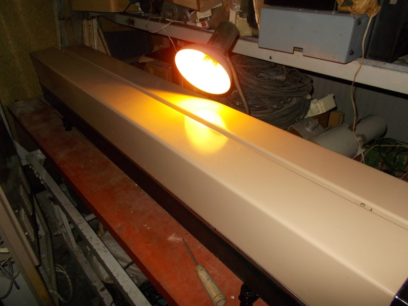
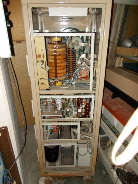
While working with such a laser in the laboratory, I realized that I could not count on the purchase of a ready-made installation, despite the attempts made. It is too large, heavy and expensive. Like any laser, it consists of two main parts - the radiator and the power source. Here is what one of the earliest models of such a laser looks like - LGI-101. The emitter is almost 2 meters long, and the power source has the size of a “full-fledged” household refrigerator. And weighs like 4 refrigerators. The claimed laser power in total for both radiation lines is 5 watts when consumed at 2.5 kW. The appearance of the radiator and power source can be seen in the photographs:
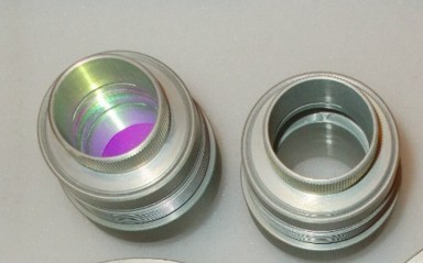
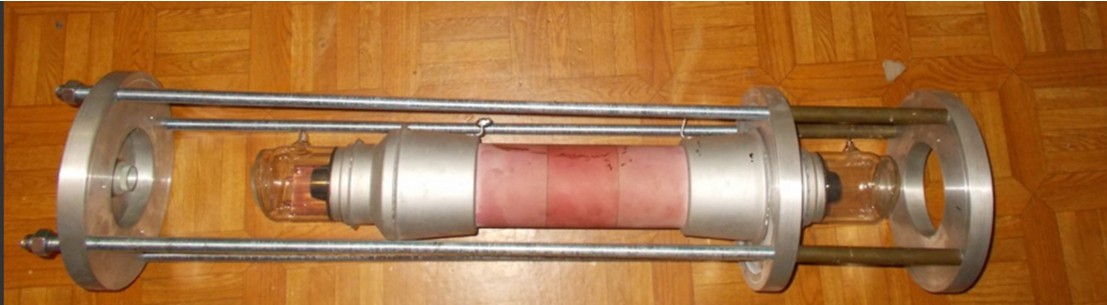
The emitter, in turn, consists of its own set of parts: the most important is the active element, then the resonator mirrors, the cooling system and the body in which all of this is put together. The power source consists of a number of functional blocks, which are described below. Therefore, I had to limit myself to searching for only the irreplaceable part - the active element (gas-discharge laser tube), and then mobilize all my experience and swag to build all that is missing. After some time, with invaluable help from my friends, I finally received the cherished wooden box in the mail, with a completely new active element like the UL-102 Kvant, a more recent development than LGI-101. Compared with LGI-101, the UL-102 is almost half the size, it produces exactly the same radiation power, and the power consumption is 1.5 times less, i.e. It is much more economical. "Naked" active element (AE) of the UL-102 looks like this.
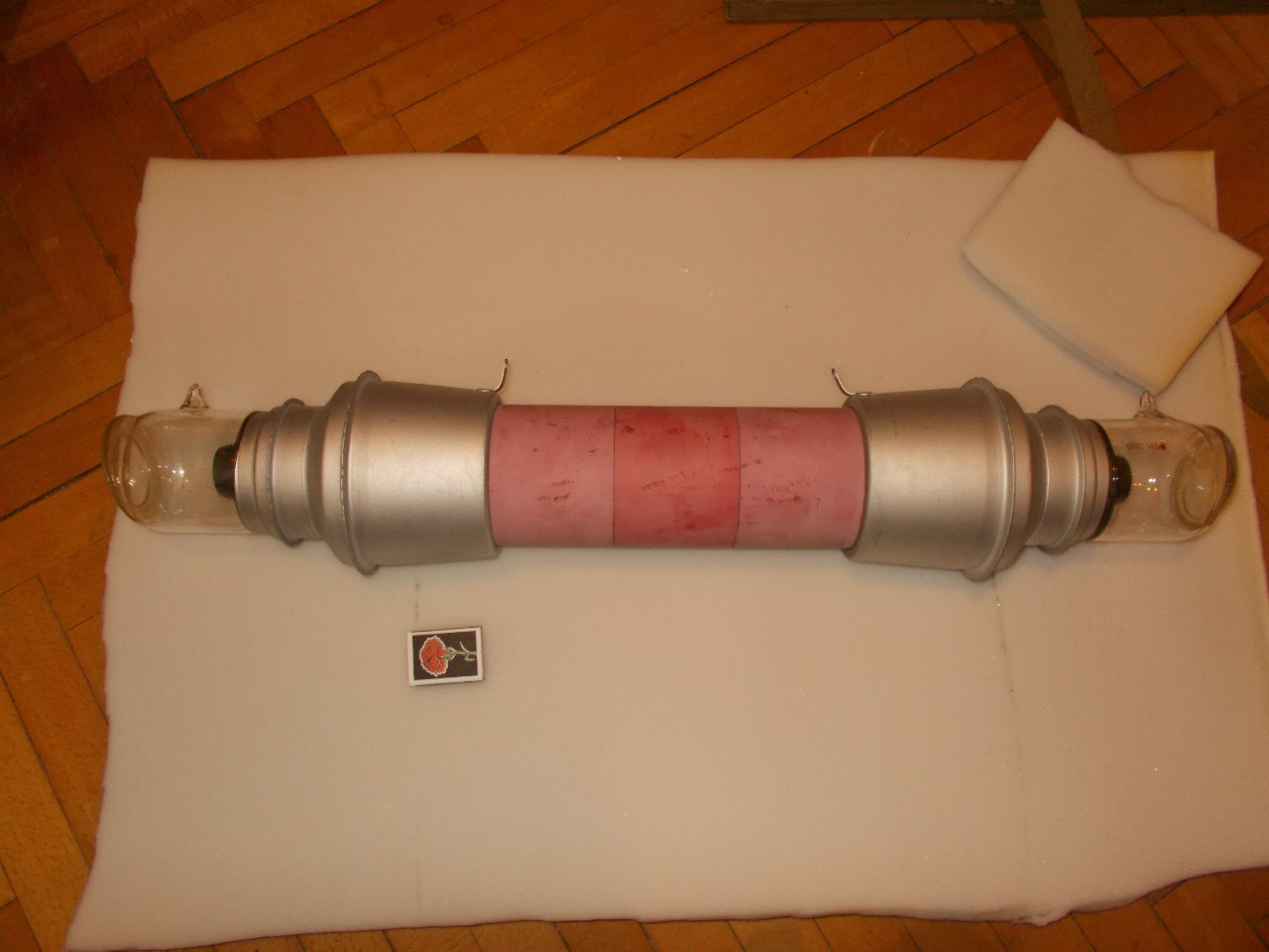
This is a massive device made of metal, ceramics and glass. It is inside it that electrical energy is converted into a high-current gas discharge, from the heat of which metallic copper evaporates, and in which the copper atoms pass into an excited state. During the transition from the excited state to the ground state, the atoms emit photons, which, when colliding with other excited atoms, will emit new photons, so that the light does not increase to the maximum possible value, which is determined by the degree of excitation of the active medium. In order for the light to freely pass through the laser tube and amplify in it, there are massive optical windows at the ends, and to heat the copper to its evaporation temperature to spend less power, good thermal insulation is required for the inner ceramic discharge tube, which is enclosed in the outer case of pink ceramic. . Electric energy is supplied to the two metal electrodes outside, and inside the tube there is neon under reduced relative to atmospheric pressure. It is the discharge in neon that serves as the primary heat source for evaporation of copper, located in the form of small pieces inside the discharge channel, there are no vapors in the cold tube, and it would be impossible to ignite the discharge if there was a full vacuum. Together with the laser tube I got a set of resonator mirrors.
Thus, the most important details already appeared to me.
I already had an idea about the principle of operation of this laser and what is needed in order to get powerful coherent radiation from a set of spare parts. It was necessary to come up with an optimal thermal stabilization system for the active element, put everything together in the form of a laser emitter, and most importantly, build a power source.
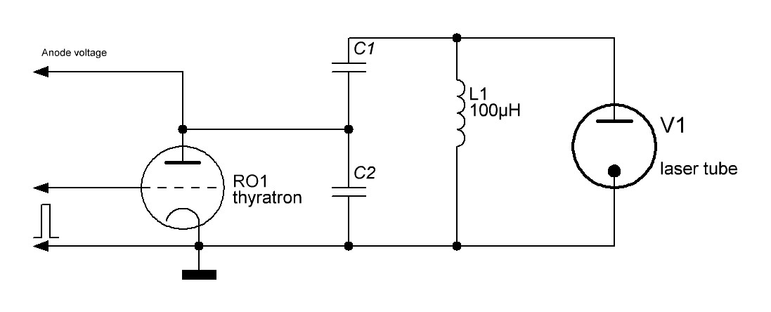
From the literature it is known that a copper vapor laser can operate only in a pulsed mode. The pulse repetition rate for the UL-102 tube can vary from 6 to 16 kHz. Each individual supply pulse must have a steep rising edge of the current through the discharge. Ideally, the steepness of the current front through the discharge will be at the level of 50 nanoseconds, which is commensurate with the lifetime of the excited state of the copper atoms, and the magnitude of the current in the pulse will be several hundred amperes with a pulse duration of 300 to 1000 ns. Generally speaking, the lasing will turn out with a smaller steepness of the front, at the level of 100 ns, and even 300 ns, but its efficiency will be much worse. It should also be noted that the voltage on the tube electrodes in the pre-breakdown moment should be at least 10 kV, and preferably more. The average power supplied to the discharge by individual pulses should be sufficient to heat and maintain the optimum temperature of copper vapor, and for the UL-102 the minimum value of this power is 1600 watts. There was some good news: copper vapor has the highest gain. This means that the requirements for the accuracy of the alignment of the resonator are very liberal (special high-precision fixtures are not needed for mounting and adjusting the position of the mirrors). In addition, the gain is higher, the higher the concentration of copper atoms in the discharge, i.e. if it is heated sufficiently strongly, then generation can be obtained not with two, but with one mirror, or even without them (single-pass amplification of spontaneous emission or “superluminescence”). This greatly facilitated the task of building a primary layout, i.e. the task was simplified until the construction of only the power source, and the construction of the radiator can be postponed until that time when the subtleties with the power will be worked out. Now about nutrition. If you look at the power supply circuit of the tube, then at first glance everything is extremely simple. Literally a few details, using the simplest topology, which in the literature is called the “direct excitation scheme”.
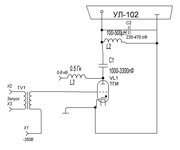
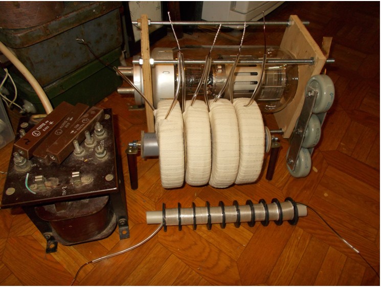
It's simple - 2 inductors, 2 capacitors, a switching thyratron, a transformer for controlling the thyratron. Everything is just not yet look at the nominal details and requirements for them. Since the task is to obtain a good steepness of the current pulse front through the active element, the thyratron needs a fast-acting, hydrogen-filled, high reverse voltage and high switched current. The desired minimum pulse current for a thyratron is 500 amps. Better - 1000 or more. Reverse voltage should be at least 20, preferably 25 kV. Such tiratrony usually used in radar and get them is not easy. But I was lucky. The couple was lying around in the rubble of the swag. Glance fell on the beautiful glass TGI-700 \ 25, the size of a two-liter bottle of soda. In terms of nominal parameters, it fits, only the relatively low (700 Hz) claimed speed is embarrassing, but so far it has been decided to try to use it. Capacitors. From 1,000 to 3,300 pF of the main cumulative and 235-470 pF additional between the tube electrodes. Ugh, just something. But! Operating voltage is needed from 15 kV. And extremely desirable low losses at high frequency, parasitic inductance should be minimized. After all, I need to get a short current through the tube, otherwise I would not see coherent photons as my own ears. It means that only ceramic capacitors with high permissible reactive power are suitable, which are used in tube radio transmitters and the same radars. Ffuh, you can breathe out, I have these too, because I have accumulated since the time when I was engaged in Tesla. Inductance. But with them it is already more difficult ... Until now, I did not need chokes in my handicrafts, at least of this magnitude, in 0.5 Gn, and even without a core, with high electrical strength. This choke is needed for the so-called. "Resonant charge" storage capacitors. In this mode, the charging process occurs with maximum efficiency, and the voltage across the capacitor can be doubled relative to the power supply. I had to wind such a choke from several sections, since there is experience. By connecting the required number of sections, it was possible to adjust the inductance in steps, and by changing the distance between them, the inductance can be adjusted smoothly within certain limits. With the second blocking choke, which is needed to prevent the flow of direct current through the active element, it is much simpler - there the necessary inductance is 100-300 μH, but the electrical strength is also needed high. Therefore, I also wound on the frame, divided into sections. This is how the first “soup set” looked like for the most important, as I called it, power section of the power supply.
But this is not enough. In order for the thyratron to work normally - a voltage source for the cathode filament is needed - the first weighty transformer appears. In order to ignite the discharge in the laser tube and switch it - you need a source of high constant voltage, while it is very desirable to be able to adjust it from 0 to 7-8 kV. Finally, you need a generator of a sufficiently powerful control signal to unlock the thyratron. Another tricky block appears to generate it. It was also easier with the latter, since there were blocks from the unsuccessful project of a Tesla lamp coil with a pulse mode, it was enough to reconfigure them to work at the desired frequency.
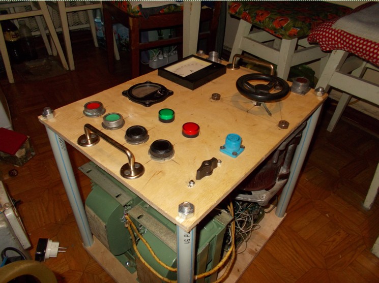
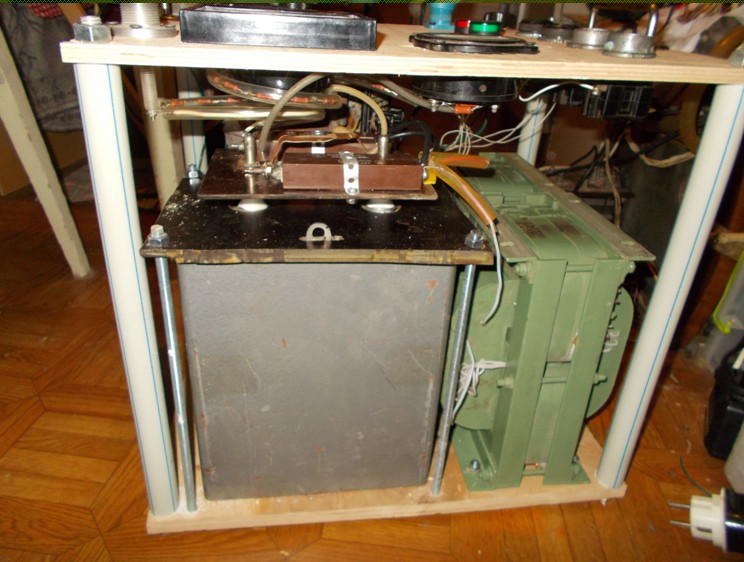
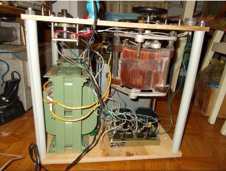
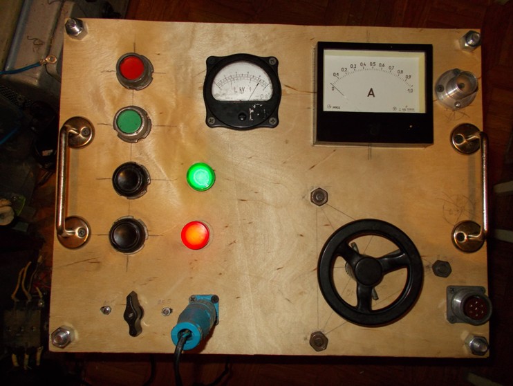
Such a model of the anode voltage subsystem of the power unit, called “IVN” - a source of high voltage, was assembled. It consisted of two power transformers, which gave in series connection up to 8 kV of alternating voltage, a rectifier in the form of a diode bridge on poles KTS201D, filter capacitor k41-1a at 2 μF 10 kV, LATPa at 9A in the primary circuit of power transformers, on and off buttons separately control generator and IVN, instruments for monitoring voltage and current.
The control generator (sub-modulator) consists of two main blocks - the master oscillator and the power amplifier. Both units are made on lamps - in the master blocking generator is used on a 6n6p lamp with a pre-amplifier on the TGI1-10 \ 1 thyratron. Power anode circuits straightened kenotron.
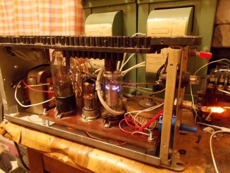
The second power amplifier unit, at this stage was assembled on the GMI-5 lamp, consists of the amplifier itself and the body kit in the form of bias sources for the first and second grids, also on kenotronic rectifiers. The anodic voltage of 2 kV is obtained with the help of a voltage doubler, also on 6d22c kenotrons. Because and so much in this block of lamps.
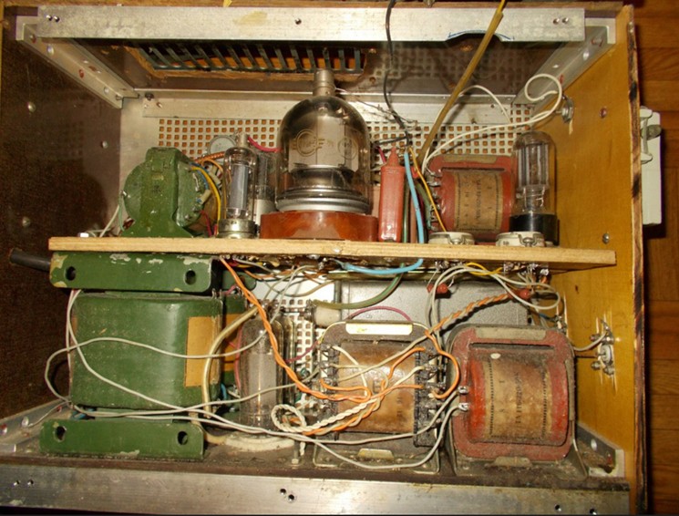
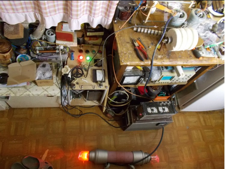
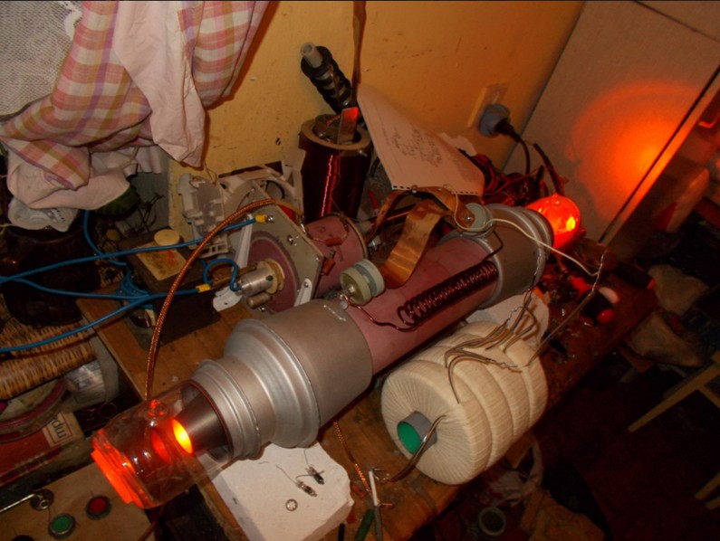
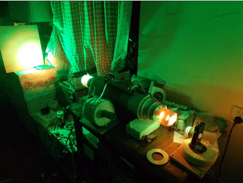
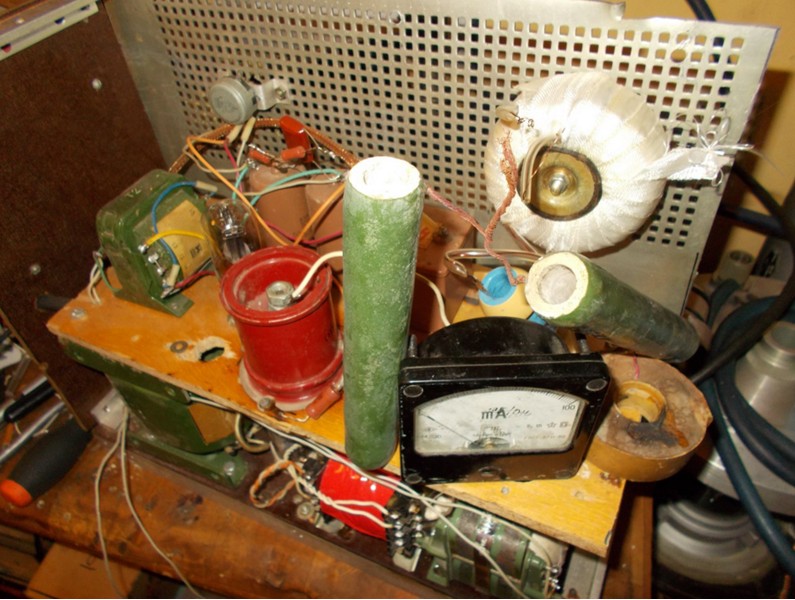
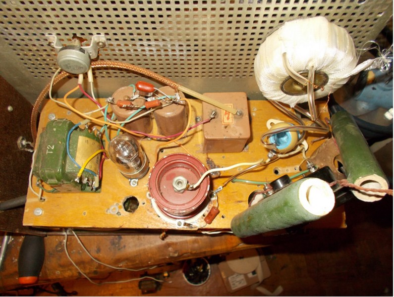
The moment came when you need to combine all the elements into a single scheme. It looked like this.
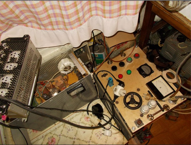
The circuit of the power unit is located on a table nearby, and was assembled “on snot”, as you may have to redo something, adjust the ratings of parts.
The launch followed immediately.
At first glance, all components interact correctly. Transformers are buzzing, a discharge is lit in the laser tube, a characteristic squeak is heard with a frequency of 10 kHz, the switching thyratron is lit, but the supply voltage has yet to be increased to the “design” 6 kV. Strictly speaking, the voltage does not play a decisive role, it is important to achieve a certain average power supplied to the discharge of the laser, which for this tube should be at least 1600 watts. It was then that the matter stalled. At the turn of 500 W, the thyratron lost controllability, simply hanging in the open position, leading to a fault in the IVN. Having played around with the pulse repetition frequency (hereinafter - CSI), the capacity of the main and additional capacitors, the inductance of the charging choke (from the large sections), we managed to overcome this line and reach the line, first in 1000 and then 1500 W. It only remained to wait for the gradual heating and the exit of the tube to the operating temperature.
However, after a short time, about 10 minutes, the tirathron lost controllability again, closing the IVN. Yes, and it became noticeable that something was wrong with the tirathron! His anode is red hot!
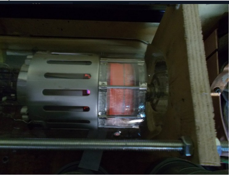
During the time when the device worked stably, the discharge channel in the laser tube also managed to heat up red-hot, for him, unlike the thyratron, it is more than full-time work. But this temperature for the discharge channel is still completely insufficient.
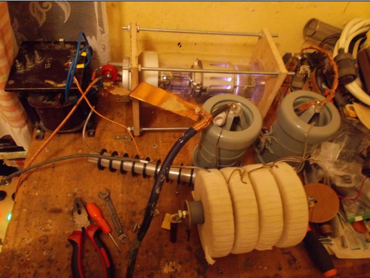
After several attempts of restarting, it became clear that in this type of thyratron the power loss is too great, we need another thyratron, more suitable. I had to extract the TGI1-1000 \ 25 thyratron from another pulsed laser, at the same time I changed the topology of the power unit to a more “advanced” circuit, the so-called. "Blumlein generator".
And the layout was completely transformed - the long connecting cable between the laser tube and the power section disappeared.
In this topology, things went better right away. The circuit worked quite stably and managed to achieve an energy input to the discharge at the level of 2000 W. The steady heating of the discharge channel began.
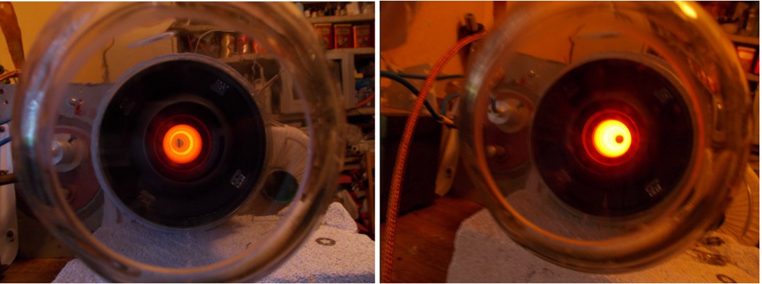
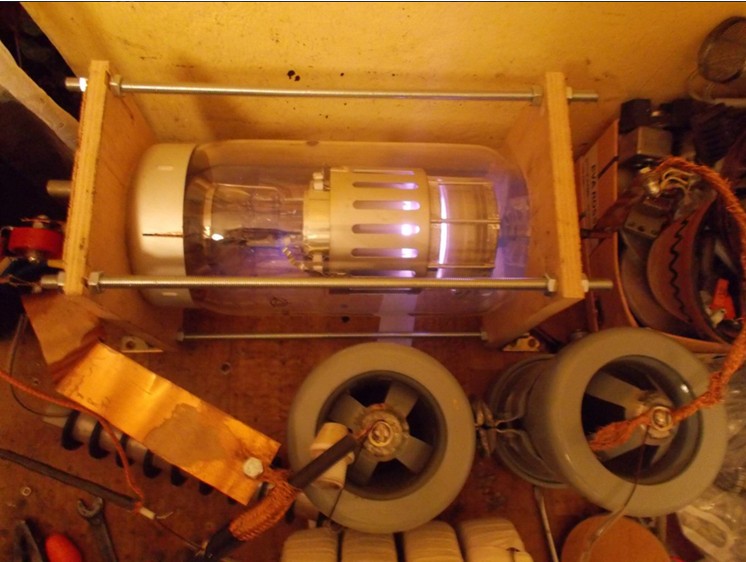
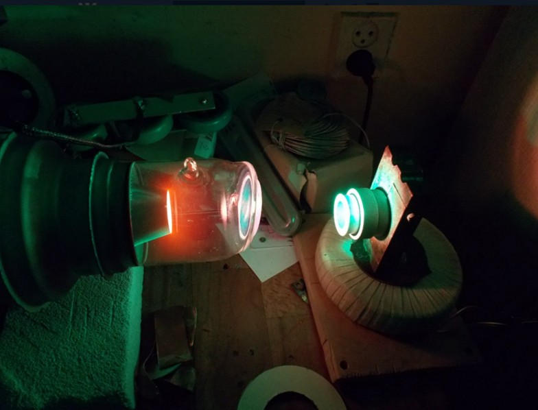
After about half an hour of work, the discharge color changed noticeably. From orange neon, he first became pink, then brightened until it became almost white, after which he acquired a dirty greenish-yellow tint. Spontaneous radiation of copper appeared, which began to evaporate. Finally, against the background of the light from the discharge, a comparatively bright green spot iridescent with speckles began to appear. Lasing began in the form of super-luminescence, i.e. without resonator mirrors. The brightness of the spot of the laser light was rapidly increasing, in a few minutes it became dazzling and bright.
If on one side of the tube a deaf mirror of the resonator is installed and its correct position is caught, then the brightness increases approximately 5 times, and the divergence of the beam decreases strongly
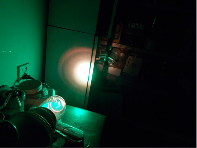
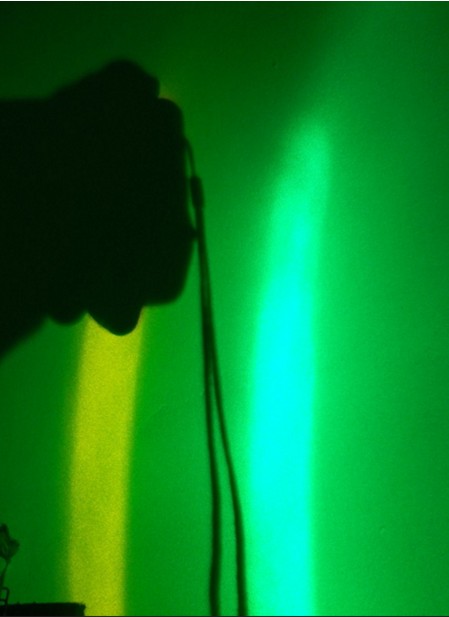
Well visible laser beam!
And if you put a lens on the path of the beam, then it is already capable of burning on plywood. That says that the light power of at least 0.5-1 watts. And this is only with one resonator mirror. So there is still a large reserve output power increase by installing a second mirror. For a homemade laser machine, this is already a great success! Especially when such power schemes are mastered for the first time.
If the beam is reflected by a fragment of a CD disk into the wall, it is clear that there are 2 components in the beam - the green and yellow, the yellow component is still less pronounced than the green.
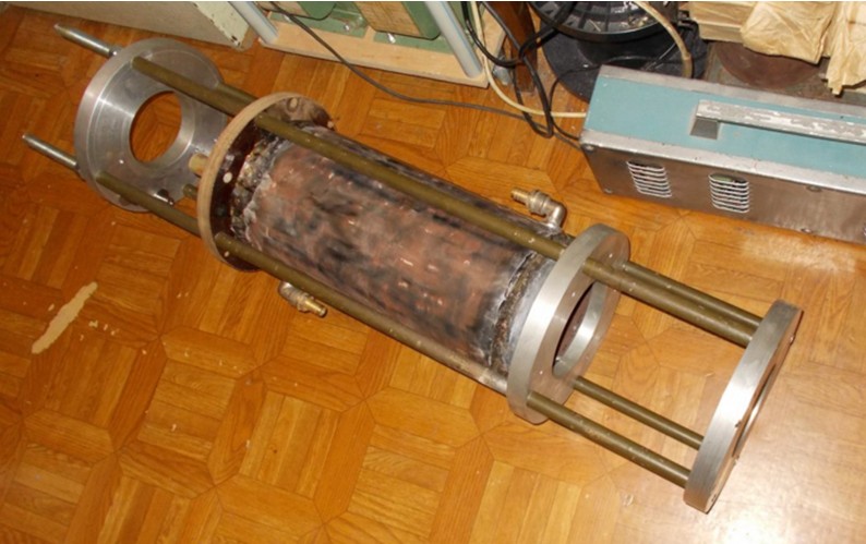
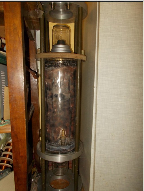
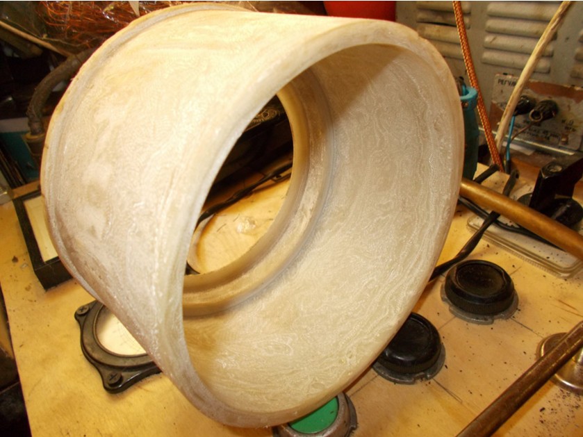
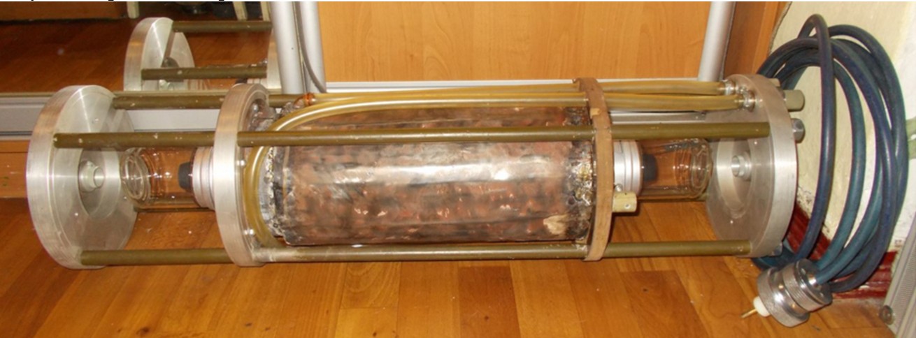
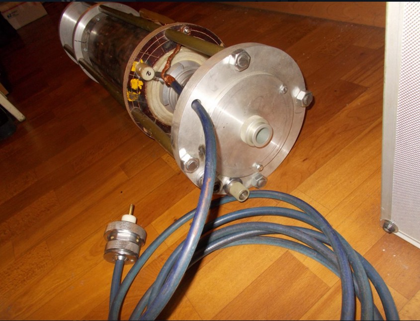
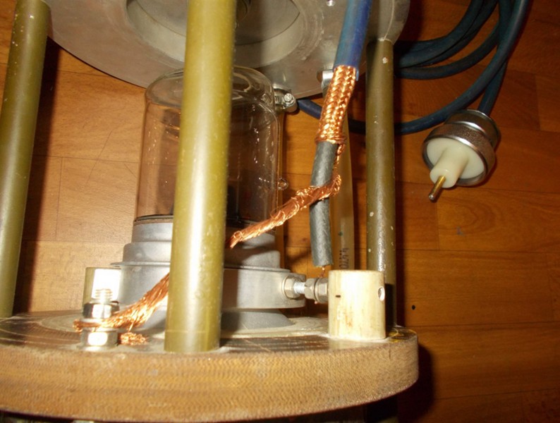
Nevertheless, in spite of the results obtained, there was one problem that did not allow to proceed to the final assembly.Namely, the instability of the operation of the thyratron in the mode when the laser is already heated to the operating temperature. With a new thorough adjustment of the mode of operation, the stability was slightly improved, and the added high-speed short-circuit protection made it possible to simply restart the IVN time after time. But LATR was already in disrepair, the insulation of its windings was seriously damaged. The experiments had to stop for a while. It was decided to focus on building the emitter. First of all, a casing with a water jacket was made, inside which a laser tube was placed. It is necessary in order to thermally stabilize the entire radiator, so that the laser body does not heat up from the very hot side surface of the AE. It also performs the function of a return current conductor located coaxially with the AE. This allows you to slightly reduce the parasitic inductance of AE.A piece of a pipe from a lamppost, purchased in the acceptance of scrap metal and fragments of the old refrigerator's lining were useful for its manufacture. The pipe was turned to the desired size, and the rings and the outer part were cut out of the casing. Rings put on the pipe, wrapped around one layer of sheet plating, and it was all soldered by hard solder. The result was a metal pipe with double walls. A mounting flange was welded on the bottom, with which this part is joined to the aluminum disc. In addition, another 2 aluminum discs were made, on which resonator mirrors are mounted, and one textolite, on which the sector mount AE is placed. All these discs are tightened with threaded rods for a solid and rigid construction. In order to avoid breakdown, the “hot” AE electrode is separated from the housing by a homemade textolite insulator.Textolite was also homemade - a sleeve was wound from glass cloth tape, each layer was coated with epoxy. Then the sleeve dried up. After the epoxy had completely dried, the bushing was turned on a lathe until the desired dimensions were obtained.
Frame radiator with a water jacket.
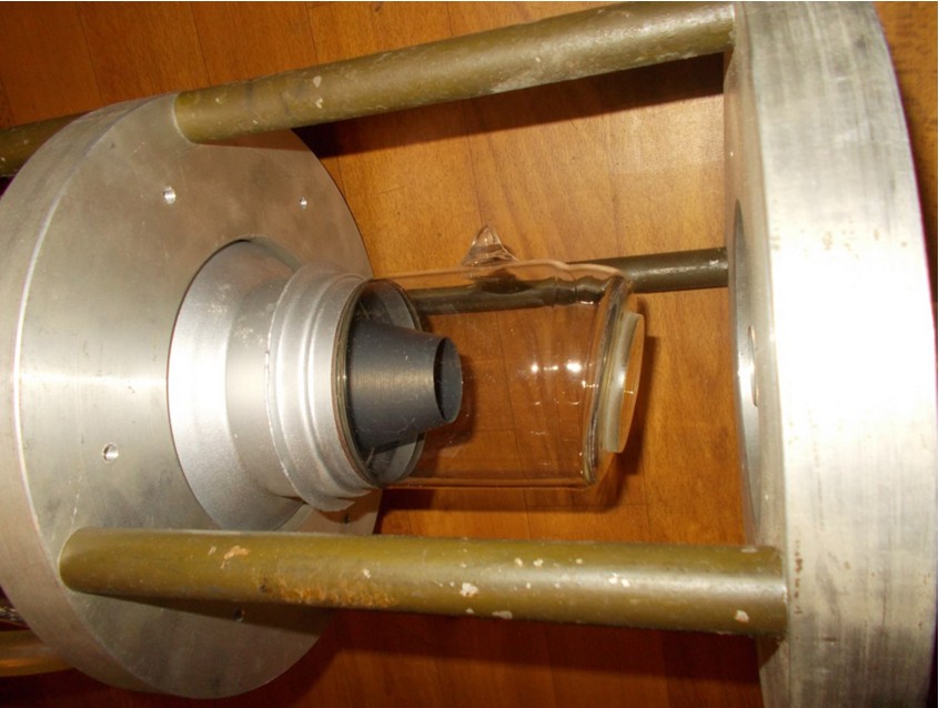
With the active element installed.
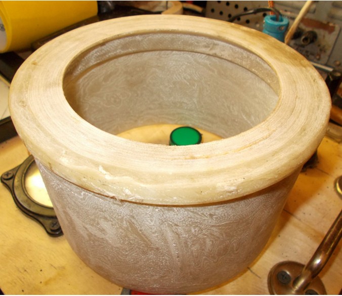
This is the active element isolator.
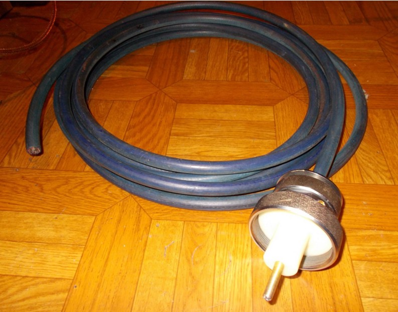
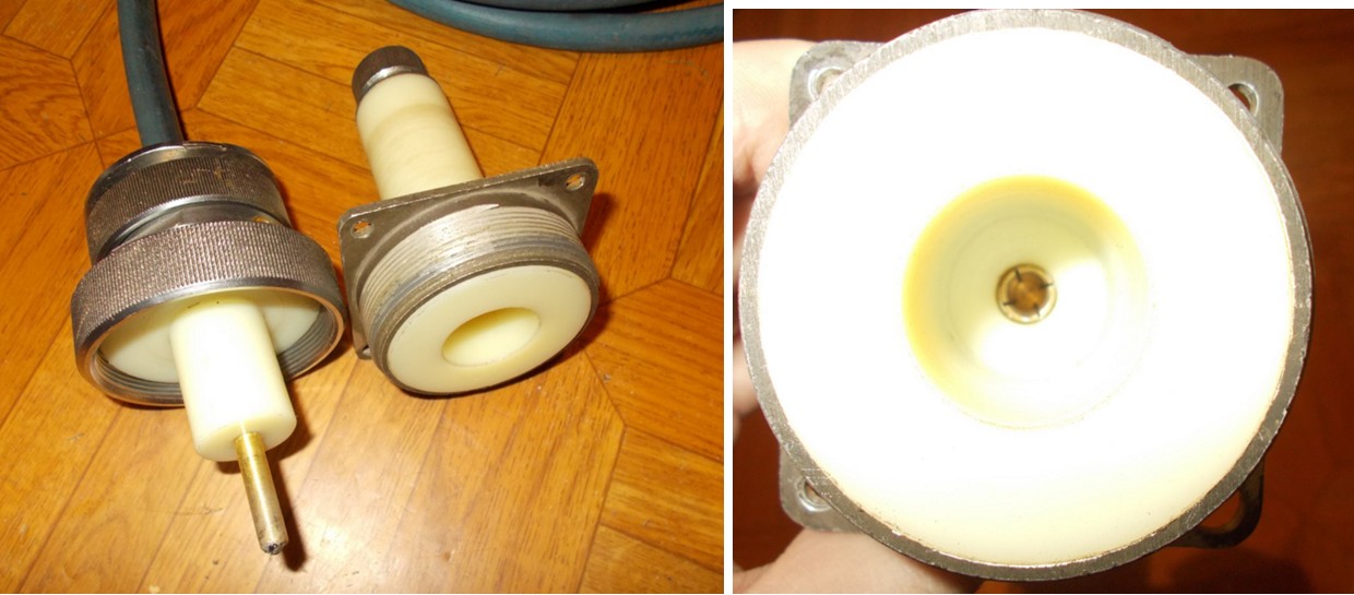
A connecting cable with a large coaxial connector designed for a voltage of 50 kV was manufactured. The body of the connector is borrowed from the LGI-21 serial laser, the core of the connector is homemade. Cable - antenna RC-50 from radar, with monolithic insulation of the central core. The role of the additional 470 pF capacitor is now played by the distributed capacitance of this connecting cable together with the parasitic capacitance of the installation.
As a result, this construction of the assembled radiator was obtained. It only remained to make the outer decorative casing, for which a sewage pipe with a diameter of 250mm was already in store. But I still put off this part of the work. It was necessary to make sure that the radiator is working properly.
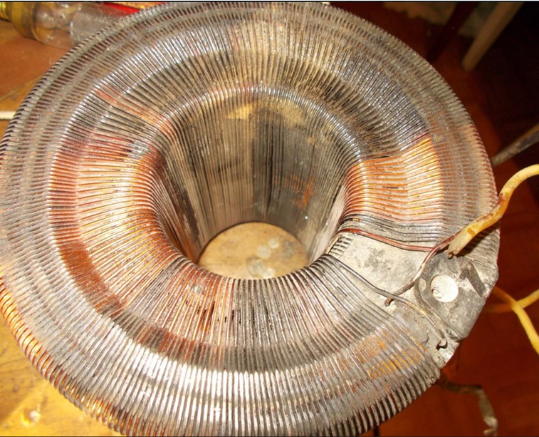
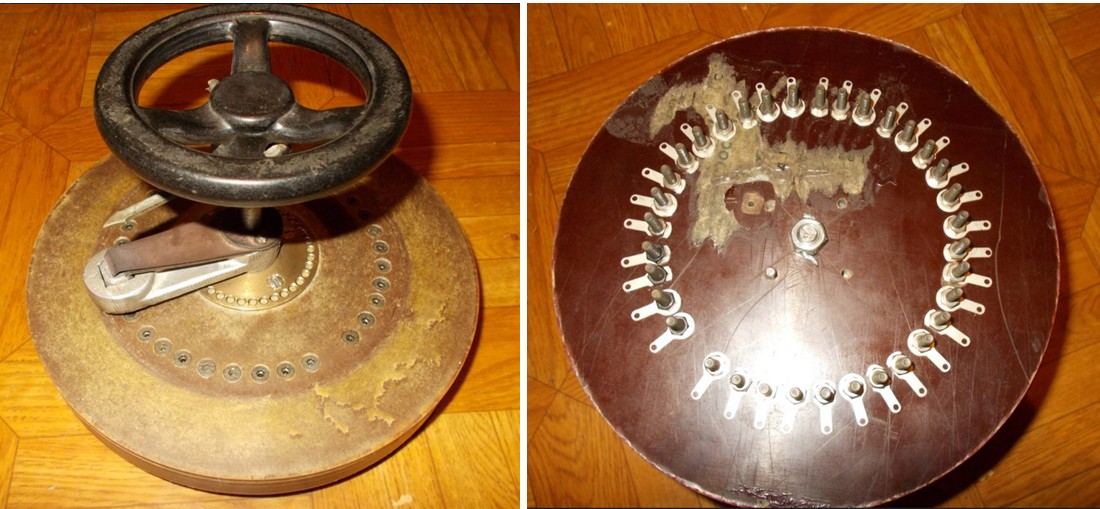
It was impossible to continue working with the practically burnt LATR; therefore, it was decided to rewind LATR, turning it into an autotransformer with fixed taps. State of the winding “before”:
And “after”
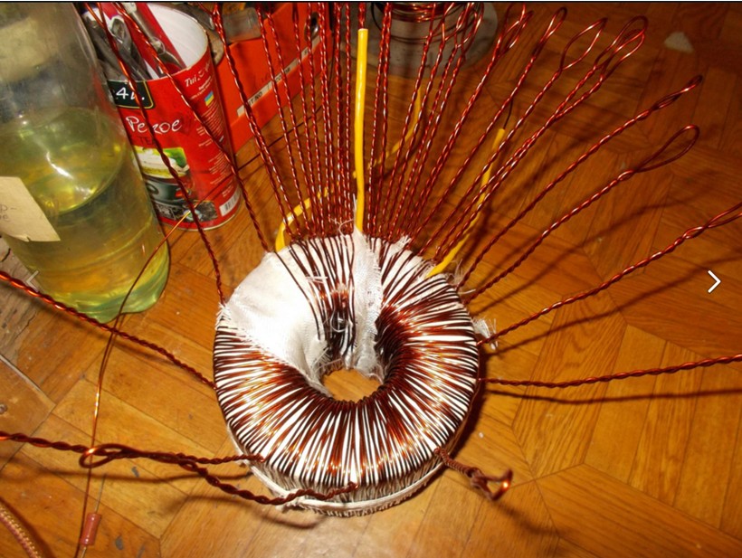
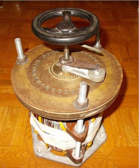
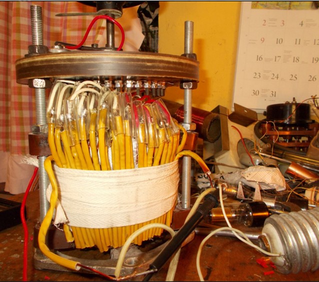
Under this winding and the frame of the former LATR, we had to make a special multi-position switch. The components of the mobile part of LATR were used.
Assembled with the winding turned out like this.
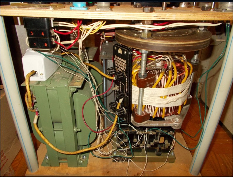
The converted autotransformer is installed in its place.
It was also added to the fast protection against short-circuit "slow" in the form of a machine in a white case. You can start a new series of experiments. Attempt to start did not work - for unknown reasons, the damaged GMI-5 lamp was detected in the power amplifier of the control signal. She leaked air on the joints of the legs with glass. Perhaps from insufficient cooling. In immediate order, the lamp is replaced by a ceramic TGI-270 \ 12 thyratron. This required some alterations in the amplifier circuit; in particular, the power grids of the grids are no longer needed.
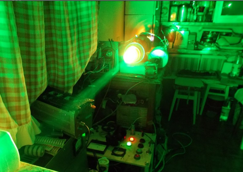
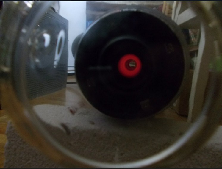
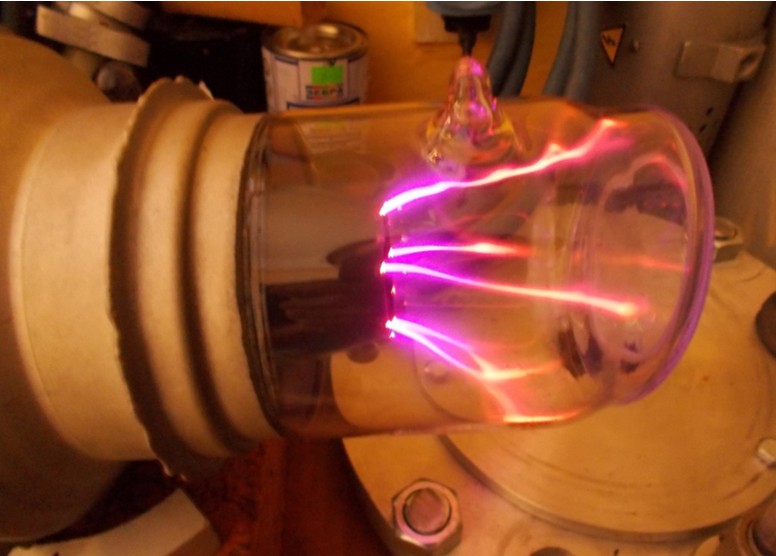
I have to note that it took about 2 months of time for all the alterations it took to manufacture the radiator carcass, to rework the autotransformer and the power amplifier. All this time, the active element was in the box. After all alterations were completed, it was removed from there, the emitter was fully assembled, and an attempt was made to start. Again unsuccessful. The active element is detected by leaked air. It looks like a discharge in it, for the photo AE was removed from the emitter.
At that moment the project had to be stopped indefinitely. See continuation in the next section.
And one more small disclaimer: this project was carried out because of my great love for the art of receiving laser radiation, in many respects for the process of its implementation, therefore I will ask not to ask the question “why is this necessary” in the comments. The information presented is shown for informational purposes only; the author is not responsible for the consequences of attempts to repeat the above.
Picture to attract attention.
')
A sequel - under the cut.
First you have to make some lyrical digression. The thing is, I am probably one of those many people who once dreamed of their lightsaber or laser gun, at least in the form in which this is possible with current technologies. And as it turned out, everything is possible, if you work on it. From the beginning of my student days, I became interested in electrical engineering, namely, the receipt of high voltages and high frequencies. So I discovered for myself such an interesting device as a Tesla transformer in its many manifestations using a variety of topologies and the most varied element base. At the same time, I realized that I was particularly attracted to the aesthetics of the diesel engine, namely, I wanted all my products to look like they came to me straight from the laboratories of Frankenstein or Tesla himself. That is why I used the element base consisting of old oil transformers, powerful radio tubes, high-frequency motor-generators (umformers), metering panel devices in a carbolite case and so on. Nevertheless, it turned out that it is already difficult to surprise anyone even with a rather long discharge from a Tesla transformer. Therefore, I decided to change the direction of activity, occupying the niche in which very few people ventured to get into. Namely - to devote his hobby to laser technology. My dream has always been to figure out what lasers are, to reveal the secrets of their device and work, and finally to build their own coherent radiation generator. As time went on, I studied a lot of literature, communicated with different people, gradually accumulated experience in the study, tuning and repair of lasers in laboratories and produced "swag" in the form of whole lasers and their fragments, which I studied in great detail.
Among the variety of lasers, one of them deserves much more attention than the others - a copper vapor laser. When I was able to see and touch such a laser at work in one of the laboratories, he created the most powerful impressions for me. And the thing is this. This is the most effective laser operating in the visible range of the spectrum, capable of having a radiation power of tens of watts at wavelengths of 510 nm (bright green) and 578 nm (saturated yellow). The beam containing both lines of radiation has a unique greenish-lemon color and is capable of burning various combustible materials just as well as an infrared CO2 laser beam. The goal was to acquire such a laser.
While working with such a laser in the laboratory, I realized that I could not count on the purchase of a ready-made installation, despite the attempts made. It is too large, heavy and expensive. Like any laser, it consists of two main parts - the radiator and the power source. Here is what one of the earliest models of such a laser looks like - LGI-101. The emitter is almost 2 meters long, and the power source has the size of a “full-fledged” household refrigerator. And weighs like 4 refrigerators. The claimed laser power in total for both radiation lines is 5 watts when consumed at 2.5 kW. The appearance of the radiator and power source can be seen in the photographs:
The emitter, in turn, consists of its own set of parts: the most important is the active element, then the resonator mirrors, the cooling system and the body in which all of this is put together. The power source consists of a number of functional blocks, which are described below. Therefore, I had to limit myself to searching for only the irreplaceable part - the active element (gas-discharge laser tube), and then mobilize all my experience and swag to build all that is missing. After some time, with invaluable help from my friends, I finally received the cherished wooden box in the mail, with a completely new active element like the UL-102 Kvant, a more recent development than LGI-101. Compared with LGI-101, the UL-102 is almost half the size, it produces exactly the same radiation power, and the power consumption is 1.5 times less, i.e. It is much more economical. "Naked" active element (AE) of the UL-102 looks like this.
This is a massive device made of metal, ceramics and glass. It is inside it that electrical energy is converted into a high-current gas discharge, from the heat of which metallic copper evaporates, and in which the copper atoms pass into an excited state. During the transition from the excited state to the ground state, the atoms emit photons, which, when colliding with other excited atoms, will emit new photons, so that the light does not increase to the maximum possible value, which is determined by the degree of excitation of the active medium. In order for the light to freely pass through the laser tube and amplify in it, there are massive optical windows at the ends, and to heat the copper to its evaporation temperature to spend less power, good thermal insulation is required for the inner ceramic discharge tube, which is enclosed in the outer case of pink ceramic. . Electric energy is supplied to the two metal electrodes outside, and inside the tube there is neon under reduced relative to atmospheric pressure. It is the discharge in neon that serves as the primary heat source for evaporation of copper, located in the form of small pieces inside the discharge channel, there are no vapors in the cold tube, and it would be impossible to ignite the discharge if there was a full vacuum. Together with the laser tube I got a set of resonator mirrors.
Thus, the most important details already appeared to me.
I already had an idea about the principle of operation of this laser and what is needed in order to get powerful coherent radiation from a set of spare parts. It was necessary to come up with an optimal thermal stabilization system for the active element, put everything together in the form of a laser emitter, and most importantly, build a power source.
From the literature it is known that a copper vapor laser can operate only in a pulsed mode. The pulse repetition rate for the UL-102 tube can vary from 6 to 16 kHz. Each individual supply pulse must have a steep rising edge of the current through the discharge. Ideally, the steepness of the current front through the discharge will be at the level of 50 nanoseconds, which is commensurate with the lifetime of the excited state of the copper atoms, and the magnitude of the current in the pulse will be several hundred amperes with a pulse duration of 300 to 1000 ns. Generally speaking, the lasing will turn out with a smaller steepness of the front, at the level of 100 ns, and even 300 ns, but its efficiency will be much worse. It should also be noted that the voltage on the tube electrodes in the pre-breakdown moment should be at least 10 kV, and preferably more. The average power supplied to the discharge by individual pulses should be sufficient to heat and maintain the optimum temperature of copper vapor, and for the UL-102 the minimum value of this power is 1600 watts. There was some good news: copper vapor has the highest gain. This means that the requirements for the accuracy of the alignment of the resonator are very liberal (special high-precision fixtures are not needed for mounting and adjusting the position of the mirrors). In addition, the gain is higher, the higher the concentration of copper atoms in the discharge, i.e. if it is heated sufficiently strongly, then generation can be obtained not with two, but with one mirror, or even without them (single-pass amplification of spontaneous emission or “superluminescence”). This greatly facilitated the task of building a primary layout, i.e. the task was simplified until the construction of only the power source, and the construction of the radiator can be postponed until that time when the subtleties with the power will be worked out. Now about nutrition. If you look at the power supply circuit of the tube, then at first glance everything is extremely simple. Literally a few details, using the simplest topology, which in the literature is called the “direct excitation scheme”.
It's simple - 2 inductors, 2 capacitors, a switching thyratron, a transformer for controlling the thyratron. Everything is just not yet look at the nominal details and requirements for them. Since the task is to obtain a good steepness of the current pulse front through the active element, the thyratron needs a fast-acting, hydrogen-filled, high reverse voltage and high switched current. The desired minimum pulse current for a thyratron is 500 amps. Better - 1000 or more. Reverse voltage should be at least 20, preferably 25 kV. Such tiratrony usually used in radar and get them is not easy. But I was lucky. The couple was lying around in the rubble of the swag. Glance fell on the beautiful glass TGI-700 \ 25, the size of a two-liter bottle of soda. In terms of nominal parameters, it fits, only the relatively low (700 Hz) claimed speed is embarrassing, but so far it has been decided to try to use it. Capacitors. From 1,000 to 3,300 pF of the main cumulative and 235-470 pF additional between the tube electrodes. Ugh, just something. But! Operating voltage is needed from 15 kV. And extremely desirable low losses at high frequency, parasitic inductance should be minimized. After all, I need to get a short current through the tube, otherwise I would not see coherent photons as my own ears. It means that only ceramic capacitors with high permissible reactive power are suitable, which are used in tube radio transmitters and the same radars. Ffuh, you can breathe out, I have these too, because I have accumulated since the time when I was engaged in Tesla. Inductance. But with them it is already more difficult ... Until now, I did not need chokes in my handicrafts, at least of this magnitude, in 0.5 Gn, and even without a core, with high electrical strength. This choke is needed for the so-called. "Resonant charge" storage capacitors. In this mode, the charging process occurs with maximum efficiency, and the voltage across the capacitor can be doubled relative to the power supply. I had to wind such a choke from several sections, since there is experience. By connecting the required number of sections, it was possible to adjust the inductance in steps, and by changing the distance between them, the inductance can be adjusted smoothly within certain limits. With the second blocking choke, which is needed to prevent the flow of direct current through the active element, it is much simpler - there the necessary inductance is 100-300 μH, but the electrical strength is also needed high. Therefore, I also wound on the frame, divided into sections. This is how the first “soup set” looked like for the most important, as I called it, power section of the power supply.
But this is not enough. In order for the thyratron to work normally - a voltage source for the cathode filament is needed - the first weighty transformer appears. In order to ignite the discharge in the laser tube and switch it - you need a source of high constant voltage, while it is very desirable to be able to adjust it from 0 to 7-8 kV. Finally, you need a generator of a sufficiently powerful control signal to unlock the thyratron. Another tricky block appears to generate it. It was also easier with the latter, since there were blocks from the unsuccessful project of a Tesla lamp coil with a pulse mode, it was enough to reconfigure them to work at the desired frequency.
Such a model of the anode voltage subsystem of the power unit, called “IVN” - a source of high voltage, was assembled. It consisted of two power transformers, which gave in series connection up to 8 kV of alternating voltage, a rectifier in the form of a diode bridge on poles KTS201D, filter capacitor k41-1a at 2 μF 10 kV, LATPa at 9A in the primary circuit of power transformers, on and off buttons separately control generator and IVN, instruments for monitoring voltage and current.
The control generator (sub-modulator) consists of two main blocks - the master oscillator and the power amplifier. Both units are made on lamps - in the master blocking generator is used on a 6n6p lamp with a pre-amplifier on the TGI1-10 \ 1 thyratron. Power anode circuits straightened kenotron.
The second power amplifier unit, at this stage was assembled on the GMI-5 lamp, consists of the amplifier itself and the body kit in the form of bias sources for the first and second grids, also on kenotronic rectifiers. The anodic voltage of 2 kV is obtained with the help of a voltage doubler, also on 6d22c kenotrons. Because and so much in this block of lamps.
The moment came when you need to combine all the elements into a single scheme. It looked like this.
The circuit of the power unit is located on a table nearby, and was assembled “on snot”, as you may have to redo something, adjust the ratings of parts.
The launch followed immediately.
At first glance, all components interact correctly. Transformers are buzzing, a discharge is lit in the laser tube, a characteristic squeak is heard with a frequency of 10 kHz, the switching thyratron is lit, but the supply voltage has yet to be increased to the “design” 6 kV. Strictly speaking, the voltage does not play a decisive role, it is important to achieve a certain average power supplied to the discharge of the laser, which for this tube should be at least 1600 watts. It was then that the matter stalled. At the turn of 500 W, the thyratron lost controllability, simply hanging in the open position, leading to a fault in the IVN. Having played around with the pulse repetition frequency (hereinafter - CSI), the capacity of the main and additional capacitors, the inductance of the charging choke (from the large sections), we managed to overcome this line and reach the line, first in 1000 and then 1500 W. It only remained to wait for the gradual heating and the exit of the tube to the operating temperature.
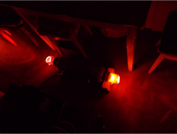
However, after a short time, about 10 minutes, the tirathron lost controllability again, closing the IVN. Yes, and it became noticeable that something was wrong with the tirathron! His anode is red hot!
During the time when the device worked stably, the discharge channel in the laser tube also managed to heat up red-hot, for him, unlike the thyratron, it is more than full-time work. But this temperature for the discharge channel is still completely insufficient.
After several attempts of restarting, it became clear that in this type of thyratron the power loss is too great, we need another thyratron, more suitable. I had to extract the TGI1-1000 \ 25 thyratron from another pulsed laser, at the same time I changed the topology of the power unit to a more “advanced” circuit, the so-called. "Blumlein generator".
And the layout was completely transformed - the long connecting cable between the laser tube and the power section disappeared.
In this topology, things went better right away. The circuit worked quite stably and managed to achieve an energy input to the discharge at the level of 2000 W. The steady heating of the discharge channel began.
After about half an hour of work, the discharge color changed noticeably. From orange neon, he first became pink, then brightened until it became almost white, after which he acquired a dirty greenish-yellow tint. Spontaneous radiation of copper appeared, which began to evaporate. Finally, against the background of the light from the discharge, a comparatively bright green spot iridescent with speckles began to appear. Lasing began in the form of super-luminescence, i.e. without resonator mirrors. The brightness of the spot of the laser light was rapidly increasing, in a few minutes it became dazzling and bright.
If on one side of the tube a deaf mirror of the resonator is installed and its correct position is caught, then the brightness increases approximately 5 times, and the divergence of the beam decreases strongly
Well visible laser beam!
And if you put a lens on the path of the beam, then it is already capable of burning on plywood. That says that the light power of at least 0.5-1 watts. And this is only with one resonator mirror. So there is still a large reserve output power increase by installing a second mirror. For a homemade laser machine, this is already a great success! Especially when such power schemes are mastered for the first time.
If the beam is reflected by a fragment of a CD disk into the wall, it is clear that there are 2 components in the beam - the green and yellow, the yellow component is still less pronounced than the green.
Nevertheless, in spite of the results obtained, there was one problem that did not allow to proceed to the final assembly.Namely, the instability of the operation of the thyratron in the mode when the laser is already heated to the operating temperature. With a new thorough adjustment of the mode of operation, the stability was slightly improved, and the added high-speed short-circuit protection made it possible to simply restart the IVN time after time. But LATR was already in disrepair, the insulation of its windings was seriously damaged. The experiments had to stop for a while. It was decided to focus on building the emitter. First of all, a casing with a water jacket was made, inside which a laser tube was placed. It is necessary in order to thermally stabilize the entire radiator, so that the laser body does not heat up from the very hot side surface of the AE. It also performs the function of a return current conductor located coaxially with the AE. This allows you to slightly reduce the parasitic inductance of AE.A piece of a pipe from a lamppost, purchased in the acceptance of scrap metal and fragments of the old refrigerator's lining were useful for its manufacture. The pipe was turned to the desired size, and the rings and the outer part were cut out of the casing. Rings put on the pipe, wrapped around one layer of sheet plating, and it was all soldered by hard solder. The result was a metal pipe with double walls. A mounting flange was welded on the bottom, with which this part is joined to the aluminum disc. In addition, another 2 aluminum discs were made, on which resonator mirrors are mounted, and one textolite, on which the sector mount AE is placed. All these discs are tightened with threaded rods for a solid and rigid construction. In order to avoid breakdown, the “hot” AE electrode is separated from the housing by a homemade textolite insulator.Textolite was also homemade - a sleeve was wound from glass cloth tape, each layer was coated with epoxy. Then the sleeve dried up. After the epoxy had completely dried, the bushing was turned on a lathe until the desired dimensions were obtained.
Frame radiator with a water jacket.
With the active element installed.
This is the active element isolator.
A connecting cable with a large coaxial connector designed for a voltage of 50 kV was manufactured. The body of the connector is borrowed from the LGI-21 serial laser, the core of the connector is homemade. Cable - antenna RC-50 from radar, with monolithic insulation of the central core. The role of the additional 470 pF capacitor is now played by the distributed capacitance of this connecting cable together with the parasitic capacitance of the installation.
As a result, this construction of the assembled radiator was obtained. It only remained to make the outer decorative casing, for which a sewage pipe with a diameter of 250mm was already in store. But I still put off this part of the work. It was necessary to make sure that the radiator is working properly.
It was impossible to continue working with the practically burnt LATR; therefore, it was decided to rewind LATR, turning it into an autotransformer with fixed taps. State of the winding “before”:
And “after”
Under this winding and the frame of the former LATR, we had to make a special multi-position switch. The components of the mobile part of LATR were used.
Assembled with the winding turned out like this.
The converted autotransformer is installed in its place.
It was also added to the fast protection against short-circuit "slow" in the form of a machine in a white case. You can start a new series of experiments. Attempt to start did not work - for unknown reasons, the damaged GMI-5 lamp was detected in the power amplifier of the control signal. She leaked air on the joints of the legs with glass. Perhaps from insufficient cooling. In immediate order, the lamp is replaced by a ceramic TGI-270 \ 12 thyratron. This required some alterations in the amplifier circuit; in particular, the power grids of the grids are no longer needed.
I have to note that it took about 2 months of time for all the alterations it took to manufacture the radiator carcass, to rework the autotransformer and the power amplifier. All this time, the active element was in the box. After all alterations were completed, it was removed from there, the emitter was fully assembled, and an attempt was made to start. Again unsuccessful. The active element is detected by leaked air. It looks like a discharge in it, for the photo AE was removed from the emitter.
At that moment the project had to be stopped indefinitely. See continuation in the next section.
Source: https://habr.com/ru/post/429332/
All Articles