Linux kernel boot. Part 1
From bootloader to kernel
If you read the previous articles , you know about my new hobby for low-level programming. I have written several articles on programming in assembler for
I am very interested in understanding how low-level things work: how programs run on my computer, how they are located in memory, how the kernel manages processes and memory, how the network stack works at a low level and much more. So, I decided to write another series of articles on the Linux kernel for the x86_64 architecture .
')
Please note that I am not a professional kernel developer and do not write kernel code at work. This is just a hobby. I just like low-level things and it's interesting to dig into them. Therefore, if you notice any confusion or have any questions / comments, contact me on twitter , by mail, or simply create a ticket . I will be grateful.
All articles are published in the GitHub repository , and if something is wrong with my English or article content, feel free to send a pull-request.
Please note that this is not official documentation, but simply training and knowledge sharing.
Required knowledge
Anyway, if you are just starting to learn such tools, I will try to explain something in this and the following articles. Okay, with the introduction finished, it's time to dive into the Linux kernel and low-level stuff.
I started writing this book in the days of the Linux 3.18 kernel, and a lot could have changed since then. If there are changes, I will update the articles accordingly.
Although these are articles on the Linux kernel, we have not yet reached it - at least in this paragraph. As soon as you press the magic power button on your laptop or desktop computer, it starts working. The motherboard sends a signal to the power supply . After receiving the signal, it provides the computer with the necessary amount of electricity. As soon as the motherboard receives a “Power OK” signal , it tries to start the CPU. He drops all the remaining data in his registers and sets the predefined values for each of them.
Processors 80386 and later should have the following values in the CPU registers after a reboot:
The processor starts to work in real mode . Let's go back a little and try to understand the memory segmentation in this mode. Real mode is supported on all x86-compatible processors: from 8086 to modern 64-bit Intel processors. The 8086 processor uses a 20-bit address bus, that is, it can work with an address space of
Memory segmentation is needed to use the entire available address space. All memory is divided into small fixed-size segments of
The address consists of two parts: 1) a segment selector with a base address; 2) offset from the base address. In real mode, the base address of the segment
For example, if the
But if we take the selector of the largest segment and the offset
that is,
Well, now we know a little about real mode and memory addressing in this mode. Returning to the discussion of register values after a reset.
The
The starting address is formed by adding the base address to the value in the EIP register:
We get
Here we see the opcode ( opcode )
We also see that the
Now the BIOS is running; After initializing and checking the BIOS hardware, you need to find the boot device. The boot order is stored in the BIOS configuration. When trying to boot from the hard disk BIOS tries to find the boot sector. On disks with partitioning MBR, the boot sector is stored in the first 446 bytes of the first sector, where each sector is 512 bytes. The last two bytes of the first sector are
For example:
We collect and run:
QEMU receives a command to use the binary
You will see:
In this example, we see that the code runs in a 16-bit real mode and starts at address
A binary dump can be viewed with the
Of course, in the real boot sector - the code to continue the boot process and the partition table instead of a heap of zeros and an exclamation mark :). From this moment on, the BIOS transfers control to the loader.
Note : As explained above, the CPU is in real mode; where the calculation of the physical address in memory is as follows:
We have only 16-bit general-purpose registers, and the maximum value of the 16-bit register is
where
In general, real-mode memory addressing is as follows:
At the beginning of the article it is written that the first instruction for the processor is located at
At the beginning of the execution of the BIOS is not in RAM, but in ROM.
The Linux kernel can be loaded with different boot loaders, such as GRUB 2 and syslinux . The kernel has a boot protocol that defines boot requirements for implementing Linux support. In this example, we are working with GRUB 2.
Continuing the boot process, the BIOS chose the boot device and transferred control to the boot sector, execution begins with boot.img . Due to the limited size, this is a very simple code. It contains a pointer to go to the main GRUB 2 image. It starts with diskboot.img and is usually stored immediately after the first sector in the unused space before the first partition. The above code loads into memory the rest of the image that contains the GRUB 2 kernel and the drivers for processing file systems. After that, the grub_main function is executed .
The
As stated in the kernel boot protocol, the bootloader must read and fill in some of the kernel installation header fields, which start at offset
The loader must fill this and other headers (which are marked only as type
As you can see in the kernel boot protocol, the memory will be displayed as follows:
So, when the loader transfers control to the kernel, it starts with the address:
where

The loader transferred the Linux kernel to memory, filled in the header fields, and then moved to the appropriate memory address. Now we can go directly to the kernel installation code.
We are finally at the core! Although technically it is not yet running. First, the kernel installation part has to adjust something, including the decompressor and some things with memory management. After all this, she will unpack the real core and go to it. The installation starts at arch / x86 / boot / header.S with the _start symbol.
At first glance, this may seem a little strange, since there are several instructions in front of it. But a long time ago, the Linux kernel had its own loader. Now, if you run, for example,
you will see:

Actually, the file
It is needed to load the operating system with UEFI support. His device will consider in the following chapters.
The actual entry point for the kernel installation:
The loader (grub2 and others) knows about this point (offset
Kernel installation entry point:
Here we see the operation code
This is the first actually executed code (except for the previous transition instructions, of course). After part of the kernel installation gets control from the loader, the first
In our case, the kernel is loaded at
After moving to
Let's see how this is implemented.
First of all, the kernel checks that the registers of the
As I wrote earlier, grub2 by default loads the kernel installation code at
This offset is
This instruction pushes the value of
Almost all of this code is part of the process of preparing the environment for the C language in real mode. The next step is to check the value of the
This can trigger three different scenarios:
Consider all the scenarios in order:
Here we set the

and as indicated in the download protocol:
If the
Two more steps are needed before moving on to the main C code: this is setting up the BSS area and checking the “magic” signature. First check signature:
The instruction simply compares setup_sig with the magic number 0x5a5aaa55. If they are not equal, a fatal error is reported.
If the magic number is the same and we have a set of correct segment registers and a stack, then it remains only to configure the BSS section before proceeding to code C.
The BSS section is used to store statically allocated uninitialized data. Linux carefully checks that this area of memory has zeroed out:
First, the starting address of __bss_start is moved to
That's it: we have a stack and a BSS, so we can go to the
The
This is the end of the first part about the Linux kernel device. , , . C, Linux, ,
If you read the previous articles , you know about my new hobby for low-level programming. I have written several articles on programming in assembler for
x86_64 Linux and at the same time began to dive into the source code of the Linux kernel.I am very interested in understanding how low-level things work: how programs run on my computer, how they are located in memory, how the kernel manages processes and memory, how the network stack works at a low level and much more. So, I decided to write another series of articles on the Linux kernel for the x86_64 architecture .
')
Please note that I am not a professional kernel developer and do not write kernel code at work. This is just a hobby. I just like low-level things and it's interesting to dig into them. Therefore, if you notice any confusion or have any questions / comments, contact me on twitter , by mail, or simply create a ticket . I will be grateful.
All articles are published in the GitHub repository , and if something is wrong with my English or article content, feel free to send a pull-request.
Please note that this is not official documentation, but simply training and knowledge sharing.
Required knowledge
- Understanding C Code
- Understanding assembly code (AT & T syntax)
Anyway, if you are just starting to learn such tools, I will try to explain something in this and the following articles. Okay, with the introduction finished, it's time to dive into the Linux kernel and low-level stuff.
I started writing this book in the days of the Linux 3.18 kernel, and a lot could have changed since then. If there are changes, I will update the articles accordingly.
Magic power button, what's next?
Although these are articles on the Linux kernel, we have not yet reached it - at least in this paragraph. As soon as you press the magic power button on your laptop or desktop computer, it starts working. The motherboard sends a signal to the power supply . After receiving the signal, it provides the computer with the necessary amount of electricity. As soon as the motherboard receives a “Power OK” signal , it tries to start the CPU. He drops all the remaining data in his registers and sets the predefined values for each of them.
Processors 80386 and later should have the following values in the CPU registers after a reboot:
  IP 0xfff0
 CS selector 0xf000
 CS base 0xffff0000
The processor starts to work in real mode . Let's go back a little and try to understand the memory segmentation in this mode. Real mode is supported on all x86-compatible processors: from 8086 to modern 64-bit Intel processors. The 8086 processor uses a 20-bit address bus, that is, it can work with an address space of
0-0xFFFFF or 1 . But it has only 16-bit registers with a maximum address of 2^16-1 or 0xffff (64 kilobytes).Memory segmentation is needed to use the entire available address space. All memory is divided into small fixed-size segments of
65536 bytes (64 KB). Since with 16-bit registers we cannot access memory above 64 KB, an alternative method was developed.The address consists of two parts: 1) a segment selector with a base address; 2) offset from the base address. In real mode, the base address of the segment
* 16 . Thus, to get a physical address in memory, multiply the segment selector by 16 and add an offset to it: = * 16 + For example, if the
CS:IP register has the value 0x2000:0x0010 , then the corresponding physical address would be: >>> hex((0x2000 << 4) + 0x0010) '0x20010' But if we take the selector of the largest segment and the offset
0xffff:0xffff , we get the address: >>> hex((0xffff << 4) + 0xffff) '0x10ffef' that is,
65520 bytes after the first megabyte. Since only one megabyte is available in real mode, 0x10ffef becomes 0x00ffef with the A20 line disabled.Well, now we know a little about real mode and memory addressing in this mode. Returning to the discussion of register values after a reset.
The
CS register consists of two parts: a visible segment selector and a hidden base address. Although the base address is usually formed by multiplying the value of the segment selector by 16, but during a hardware reset, the segment selector in the CS register is set to 0xf000 , and the base address is 0xffff0000 . The processor uses this special base address until the CS changes.The starting address is formed by adding the base address to the value in the EIP register:
>>> 0xffff0000 + 0xfff0 '0xfffffff0' We get
0xfffffff0 , which is 16 bytes below 4 GB. This point is called the reset vector . This is the memory location where the CPU waits for the first instruction to be executed after a reset: a jump operation ( jmp ), which usually points to the BIOS entry point. For example, if you look at the coreboot source code ( src/cpu/x86/16bit/reset16.inc ), we will see: .section ".reset", "ax", %progbits .code16 .globl _start _start: .byte 0xe9 .int _start16bit - ( . + 2 ) ... Here we see the opcode ( opcode )
jmp , namely 0xe9 , and the destination address _start16bit - ( . + 2) .We also see that the
reset section is 16 bytes, and it is compiled to run from 0xfffff0 ( src/cpu/x86/16bit/reset16.ld ): SECTIONS { /* Trigger an error if I have an unuseable start address */ _bogus = ASSERT(_start16bit >= 0xffff0000, "_start16bit too low. Please report."); _ROMTOP = 0xfffffff0; . = _ROMTOP; .reset . : { *(.reset); . = 15; BYTE(0x00); } } Now the BIOS is running; After initializing and checking the BIOS hardware, you need to find the boot device. The boot order is stored in the BIOS configuration. When trying to boot from the hard disk BIOS tries to find the boot sector. On disks with partitioning MBR, the boot sector is stored in the first 446 bytes of the first sector, where each sector is 512 bytes. The last two bytes of the first sector are
0x55 and 0xaa . They show the BIOS that it is a bootable device.For example:
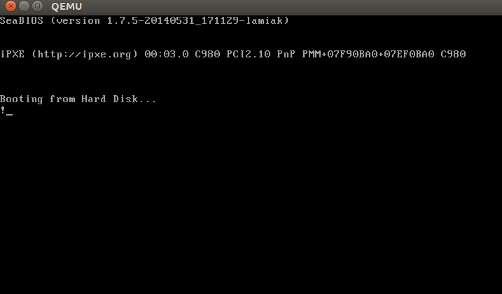
; ; : Intel x86 ; [BITS 16] boot: mov al, '!' mov ah, 0x0e mov bh, 0x00 mov bl, 0x07 int 0x10 jmp $ times 510-($-$$) db 0 db 0x55 db 0xaa We collect and run:
nasm -f bin boot.nasm && qemu-system-x86_64 bootQEMU receives a command to use the binary
boot file, which we have just created as a disk image. Since the binary file generated above satisfies the requirements of the boot sector (start at 0x7c00 and completion with a magic sequence), QEMU will treat the binary file as the master boot record (MBR) of the disk image.You will see:
In this example, we see that the code runs in a 16-bit real mode and starts at address
0x7c00 in memory. After launching, it causes a 0x10 interrupt, which simply prints the character ! ; fills the remaining 510 bytes with zeros and ends with two magic bytes 0xaa and 0x55 .A binary dump can be viewed with the
objdump utility:nasm -f bin boot.nasm
objdump -D -b binary -mi386 -Maddr16,data16,intel bootOf course, in the real boot sector - the code to continue the boot process and the partition table instead of a heap of zeros and an exclamation mark :). From this moment on, the BIOS transfers control to the loader.
Note : As explained above, the CPU is in real mode; where the calculation of the physical address in memory is as follows:
= * 16 + We have only 16-bit general-purpose registers, and the maximum value of the 16-bit register is
0xffff , so for the largest values the result will be: >>> hex((0xffff * 16) + 0xffff) '0x10ffef' where
0x10ffef is 1 + 64 - 16 . In the processor 8086 (the first processor with real mode) 20-bit address line. Since 2^20 = 1048576 , the actual available memory is 1 MB.In general, real-mode memory addressing is as follows:
  0x00000000 - 0x000003FF - table of real-mode interrupt vectors
 0x00000400 - 0x000004FF - BIOS data area
 0x00000500 - 0x00007BFF - not used
 0x00007C00 - 0x00007DFF - our bootloader
 0x00007E00 - 0x0009FFFF - not used
 0x000A0000 - 0x000BFFFF - Video RAM (VRAM) Memory
 0x000B0000 - 0x000B7777 - monochrome video memory
 0x000B8000 - 0x000BFFFF - color mode video memory
 0x000C0000 - 0x000C7FFF - Video ROM BIOS
 0x000C8000 - 0x000EFFFF - shadow area (BIOS Shadow)
 0x000F0000 - 0x000FFFFF - system BIOS
At the beginning of the article it is written that the first instruction for the processor is located at
0xFFFFFFF0 , which is much more than 0xFFFFF (1 MB). How does the CPU access this address in real mode? Answer in coreboot documentation:0xFFFE_0000 - 0xFFFF_FFFF: 128 ROMAt the beginning of the execution of the BIOS is not in RAM, but in ROM.
Loader
The Linux kernel can be loaded with different boot loaders, such as GRUB 2 and syslinux . The kernel has a boot protocol that defines boot requirements for implementing Linux support. In this example, we are working with GRUB 2.
Continuing the boot process, the BIOS chose the boot device and transferred control to the boot sector, execution begins with boot.img . Due to the limited size, this is a very simple code. It contains a pointer to go to the main GRUB 2 image. It starts with diskboot.img and is usually stored immediately after the first sector in the unused space before the first partition. The above code loads into memory the rest of the image that contains the GRUB 2 kernel and the drivers for processing file systems. After that, the grub_main function is executed .
The
grub_main function initializes the console, returns the base address for the modules, sets the root device, loads / parses the grub configuration file, loads the modules, etc. At the end of the execution, it puts grub into normal mode. The grub_normal_execute function (from the grub-core/normal/main.c source file) completes the final preparations and shows the menu for selecting the operating system. When we select one of the grub menu items, the grub_menu_execute_entry function grub_menu_execute_entry , which executes the grub boot command and loads the selected OS.As stated in the kernel boot protocol, the bootloader must read and fill in some of the kernel installation header fields, which start at offset
0x01f1 from the kernel installation code. This offset is specified in the linker script . The arch / x86 / boot / header.S kernel header begins with: .globl hdr hdr: setup_sects: .byte 0 root_flags: .word ROOT_RDONLY syssize: .long 0 ram_size: .word 0 vid_mode: .word SVGA_MODE root_dev: .word 0 boot_flag: .word 0xAA55 The loader must fill this and other headers (which are marked only as type
write in the Linux boot protocol, as in this example) with values that were received from the command line or calculated at boot time. Now we will not dwell on the descriptions and explanations for all the header fields. We'll discuss later how the kernel uses them. For a description of all the fields, see the download protocol .As you can see in the kernel boot protocol, the memory will be displayed as follows:
  |  Kernel protected mode |
 100,000 + ------------------------ +
          |  I / O mapping |
 0A0000 + ------------------------ +
          |  Reserved.  for BIOS |  Leave as much as possible free
          ~ ~
          |  Command Line |  (may also be behind the X + 10000 mark)
 X + 10,000 + ------------------------ +
          |  Stack / pile |  To use real kernel mode code
 X + 08000 + ------------------------ +
          |  Kernel installation |  Real kernel mode code
          |  Kernel boot sector |  Legacy kernel boot sector
        X + ------------------------ +
          |  Bootloader |  <- Entry point 0x7C00 boot sector
 001000 + ------------------------ +
          |  Reserved.  for MBR / BIOS |
 000800 + ------------------------ +
          |  Usually used  MBR |
 000600 + ------------------------ +
          |  Use  BIOS only |
 000000 + ------------------------ +
So, when the loader transfers control to the kernel, it starts with the address:
X + sizeof (KernelBootSector) + 1 where
X is the address of the kernel boot sector. In our case, X is 0x10000 , as seen in the memory dump:The loader transferred the Linux kernel to memory, filled in the header fields, and then moved to the appropriate memory address. Now we can go directly to the kernel installation code.
Starting the kernel installation phase
We are finally at the core! Although technically it is not yet running. First, the kernel installation part has to adjust something, including the decompressor and some things with memory management. After all this, she will unpack the real core and go to it. The installation starts at arch / x86 / boot / header.S with the _start symbol.
At first glance, this may seem a little strange, since there are several instructions in front of it. But a long time ago, the Linux kernel had its own loader. Now, if you run, for example,
qemu-system-x86_64 vmlinuz-3.18-genericyou will see:
Actually, the file
header.S starts with the magic number MZ (see screenshot of the dump above), the text of the error message and the PE header: #ifdef CONFIG_EFI_STUB # "MZ", MS-DOS header .byte 0x4d .byte 0x5a #endif ... ... ... pe_header: .ascii "PE" .word 0 It is needed to load the operating system with UEFI support. His device will consider in the following chapters.
The actual entry point for the kernel installation:
// header.S line 292 .globl _start _start: The loader (grub2 and others) knows about this point (offset
0x200 from MZ ) and goes straight to it, although header.S begins with the .bstext section, where the text of the error message is: // // arch/x86/boot/setup.ld // . = 0; // current position .bstext : { *(.bstext) } // put .bstext section to position 0 .bsdata : { *(.bsdata) } Kernel installation entry point:
.globl _start _start: .byte 0xeb .byte start_of_setup-1f 1: // // rest of the header // Here we see the operation code
jmp ( 0xeb ), which goes to the point start_of_setup-1f . In the Nf notation, for example, 2f refers to the local label 2: In our case, this is label 1 , which is present immediately after the transition, and it contains the rest of the setup header. Immediately after the installation header, we see the .entrytext section, which starts with the start_of_setup tag.This is the first actually executed code (except for the previous transition instructions, of course). After part of the kernel installation gets control from the loader, the first
jmp instruction is at offset 0x200 from the beginning of the real kernel mode, that is, after the first 512 bytes. This can be seen both in the Linux kernel boot protocol and in the grub2 source code: segment = grub_linux_real_target >> 4; state.gs = state.fs = state.es = state.ds = state.ss = segment; state.cs = segment + 0x20; In our case, the kernel is loaded at
0x10000 . This means that after starting the kernel installation, the registers of the segments will have the following values:gs = fs = es = ds = ss = 0x10000
cs = 0x10200After moving to
start_of_setup kernel should do the following:- Ensure all segment register values are the same.
- If necessary, adjust the correct stack
- Configure bss
- Go to code C in arch / x86 / boot / main.c
Let's see how this is implemented.
Alignment of segment registers
First of all, the kernel checks that the registers of the
ds and es segments point to the same address. Then clears the direction flag using the cld instruction: movw %ds, %ax movw %ax, %es cld As I wrote earlier, grub2 by default loads the kernel installation code at
0x10000 , and cs at 0x10200 , because execution does not start from the beginning of the file, but from going here: _start: .byte 0xeb .byte start_of_setup-1f This offset is
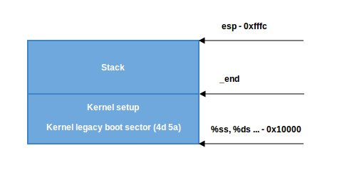
512 bytes from 4d 5a . It is also necessary to align the cs from 0x10200 to 0x10000 , as well as all the other segment registers. After that install the stack: pushw %ds pushw $6f lretw This instruction pushes the value of
ds onto the stack, followed by the address of label 6 and the instruction lretw , which loads the address of label 6 into the command counter register and loads cs with the value ds . After that, ds and cs will have the same values.Stack Setup
Almost all of this code is part of the process of preparing the environment for the C language in real mode. The next step is to check the value of the
ss register and create the correct stack if the ss value is incorrect: movw %ss, %dx cmpw %ax, %dx movw %sp, %dx je 2f This can trigger three different scenarios:
ssvalid value of0x1000(like all other registers exceptcs)ssnot a valid value, and theCAN_USE_HEAPflagCAN_USE_HEAPset (see below)ssnot a valid value, and theCAN_USE_HEAPflagCAN_USE_HEAPnot set (see below)
Consider all the scenarios in order:
ssvalid value (0x1000). In this case, we go to label 2:
2: andw $~3, %dx jnz 3f movw $0xfffc, %dx 3: movw %ax, %ss movzwl %dx, %esp sti Here we set the
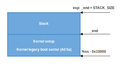
dx register alignment (which contains the sp value specified by the loader) by 4 bytes and check for zero. If it is equal to zero, then we put in dx value 0xfffc (the address aligned by 4 bytes before the maximum segment size of 64 KB). If it is not equal to zero, then we continue to use the sp value specified by the loader ( 0xf7f4 in our case). Then we put the value of ax in ss , which keeps the correct address of the segment 0x1000 and sets the correct sp . Now we have the right stack:- In the second scenario,
ss != ds. First we put the _end value (the end address of the installation code) intodxand check theloadflagsheader field using thetestbinstruction to check if the heap can be used. loadflags is a bitmask header, which is defined as follows:
#define LOADED_HIGH (1<<0) #define QUIET_FLAG (1<<5) #define KEEP_SEGMENTS (1<<6) #define CAN_USE_HEAP (1<<7) and as indicated in the download protocol:
: loadflags

.

7 (): CAN_USE_HEAP
1, ,
heap_end_ptr . ,
.
If the
CAN_USE_HEAP bit is CAN_USE_HEAP , then in dx we set the value of heap_end_ptr (which indicates _end ) and add to it STACK_SIZE (the minimum stack size is 1024 bytes). After that, go to label 2 (as in the previous case) and make the correct stack.- If
CAN_USE_HEAPnot set, simply use the minimum stack from_endto_end + STACK_SIZE:
BSS Setup
Two more steps are needed before moving on to the main C code: this is setting up the BSS area and checking the “magic” signature. First check signature:
cmpl $0x5a5aaa55, setup_sig jne setup_bad The instruction simply compares setup_sig with the magic number 0x5a5aaa55. If they are not equal, a fatal error is reported.
If the magic number is the same and we have a set of correct segment registers and a stack, then it remains only to configure the BSS section before proceeding to code C.
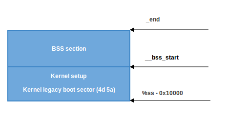
The BSS section is used to store statically allocated uninitialized data. Linux carefully checks that this area of memory has zeroed out:
movw $__bss_start, %di movw $_end+3, %cx xorl %eax, %eax subw %di, %cx shrw $2, %cx rep; stosl First, the starting address of __bss_start is moved to
di . Then the address _end + 3 (+3 for alignment by 4 bytes) is moved to cx . The eax register is cleared (using the xor instruction), the size of the bss ( cx-di ) section is calculated and it is placed in cx . Then cx is divided by four (the size of the “word”) and the instruction stosl used stosl , keeping the value di , automatically increasing di by four and repeating it until __bss_start to _end :Move to main
That's it: we have a stack and a BSS, so we can go to the
main() C function: calll main The
main() function is in arch / x86 / boot / main.c. We will talk about it in the next part.Conclusion
This is the end of the first part about the Linux kernel device. , , . C, Linux, ,
memset , memcpy , earlyprintk , .Links
Source: https://habr.com/ru/post/428664/
All Articles