3D drilling machine and PCAD to G-Code drilling card converter
Hello, dear habrozhiteli.
Today I want to share a small experience designed to convert PCAD drilling cards into G-code. Flexible, easy and open source. True, forgive me, opt for Qt. It's nice to write on it, but deploying and collecting other people's codes ...
Some time ago I put my project on the head for the Prius, and here's what:
While waiting for the chip, while experimenting with the circuits, I clearly understood that I want to make printed circuit boards at home. Yes, yes, there is the experience of laser-iron technology, and even painting with varnish, but I wanted something real. It was decided to use a film photoresist and a UV lamp for nails. Naturally, the problem of drilling and metallization of holes arose. And it turns out from there that the holes need to be metallized before the tracks are etched on the board. Otherwise, apply current to each hole - the whole story.
It turns out that manual drilling disappears, because There is simply nothing to be guided by (let's not offer papers with hole cards).
')
It was decided to hang on an existing 3D-printer instead of a Direct-head - a spindle, and so on. And here came the decisions that I would like to share today.
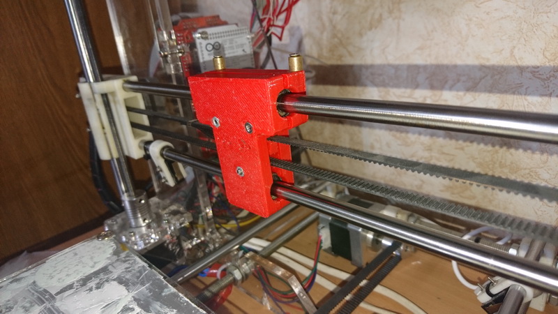
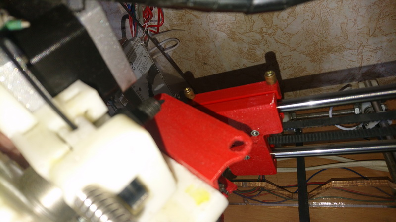
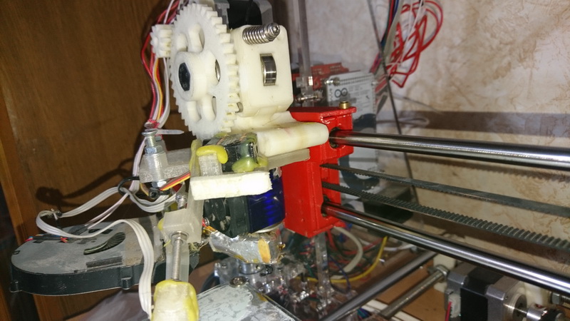
In order to easily turn the printer into a drill and back, it was decided to make the head detachable. The runner bolted to the belts is separate, and everything else is removable. Given that this is not God knows, what a complexity, it makes no sense to lay out a separate article. There is just a photo and links to the STL-model , if someone wants exactly the same. The archive also contains SLDPRT-sources, if something is corrected. It is swinging slowly - thanks to ADSL from Beltelecom, but it should lie for a long time.
The result was like this:

Everything is simple - after long attempts to create your own spindle, I decided to buy it on AliExpress, and just hang it on the bracket. There is no photo, while in the process.
And here the most interesting begins.
With globalism inherent in me, I ran through the existing solutions, and realized that each of them can not only create a lot of problems when deploying technology at home, but also deliver them regularly and methodically, right through to retirement. What didn't you like? Inflexibility. All of them are more like machines, with predefined pattern characteristics, etc. Yes, it's not difficult. But I really didn’t want to once face a situation when it was necessary to slightly modify the algorithm, and not be able to do it. For example, I did not see a tool capable of turning holes around the axis. But after metallization, the 1: 1 fee cannot be laid. But these are thoughts for the future. I don't need it yet. But it is already possible. In general, I wanted something simple, easy, flexible and ... workable. I decided to do it myself.
Qt 5.11 libraries were used as the base. The application is written in console style. The architecture of the application is made in linux-style.
The application receives the input file DRL, pulled out of PCAD when creating a Geber-kit. (you may have to modify the parser if you want to feed him something from AltiumDesigner. But for me personally I decided to tear this Altium monster away from sin. For what it is now in terrible dreams, and does not allow me to forget my own name).
An XML file is specified as a parameter. The second half of the article will be devoted to the description of the format of this file. This file, in fact, defines the mechanism for generating a G-Code (and in fact, any text file) for transmitting it (G-code) to a 3D printer.
In order to make the program as flexible as possible, the ScriptEngine library was used. He himself was a little stunned by what can now really be done with the configuration. The main postulate is this: there are many calculated parameters that are handled as transparently as possible: the text is passed to the ScriptEngine module, and the result is used. The same situation occurs if the $ {bla-bla-bla} combination is encountered in the G-Code pattern. In this case, everything inside the curly brackets will be transferred to the calculation, and the entire template will be replaced by the result.
In fact, nothing complicated, if you read. But let's analyze each section:
In the variables section, as the name implies, we can define an arbitrary set of global variables. They do not affect the operation of the program, until they meet in any calculated expression.
Functions. Well, more precisely, the function. For now, it’s a predetermined one: calculating the real diameter of the drill for metallized holes It is known that the metallization steals the diameter, and this often leads to incidents when trying to push the leg of a component of 0.8, which does not fit into the hole, laid as 0.9. In order not to bother with this when designing, I decided to add this functionality.
The meaning of this section is to define the functions that the converter can use for specific purposes. These functions cannot (yet?) Be used independently.
Drill. Here you need to make a reference to the script command "align tools", about which below. Each element of this section defines a cell into which all the tools recognized in the input file will be collected. The idea is such that often when designing, inch diameters occur, and a multitude of tools with their values 0.478 ... 0.492 ... etc. To avoid messing with them, we set the required parameters range_min and range_max. A sign of metallization is also required. XML nodes are scanned sequentially, and as soon as another tool from the DRL fits the definition, the node is considered appropriate.
You can set any other parameters in the node. Their meaning can be used later in the templates.
You can specify the position in the pencil case or coordinates where to grab the drill if you have a machine with an auto-change tool. And you can describe the tool with letters to display the printer, if you, like me, have Marlin and manually change the drills.
And now appreciate the beauty of the script machine! Templates The converter, as I have already said, works with templates simply: it looks for all pieces of the form $ {...}, and sends it to the script machine. And there is a JS-like language. Therefore, in fact, you can even program a little. In this example, you can see how, when displaying the start template, we first defined a couple of variables that were assigned global values. Well, and only then wrote a constant, which will be the value of the implementation of this piece.
When this template is output to the output file, we will see:
Well, I can not not brag. Evaluate a piece from the template for drilling each hole:
yes, yes ... every time typing a Holes rest comment, we will decrement the value of hcnt. And, as we remember, it was defined while we were typing start, and, therefore, is the context above. And then we will calculate the percent variable, so that we can use it in another piece, when we transfer it to the M73 team (this command causes the marlin to move the progress bar). The G-Code generated by this snippet:
By the way, toolsCount, minX are predefined names for global variables.
I note that the names of the templates are not predefined, i.e. You can use any. The template will be printed when the print command and its name are encountered in the script.
Inside the section there can be nodes with the names command and loop.
Command node format:
Operator action - one of the few operators. The parameters for each are described below. They can be supplemented by any others that, as you already understood, can be used in templates.
Format node loop :
a cycle is a section whose contents will be executed for each element determined by the type of cycle. There are two of them (for now):
tools - the loop will execute for the caj instrument, and
toolholes - the cycle will be executed for each hole intended for drilling with this tool. Obviously, the toolholes loop can only be nested in tools .
At the same time, when executing a nested loop, all variables for the current tool are available. What for? I do not know. Just told.
assign tools
Parameters: no.
Assigns each drill from an XML tool source file. Without it, most other actions are meaningless.
join tools
Parameters: no.
More Organizational — combines all the tools that have been assigned the same from the XML file. It makes sense immediately after the assign tools, but I decided to enable the user to do their operations.
sort tools
Parameters: none (yet).
Sorts drill bits by ascending diameters
offset
Options:
xoffs, yoffs are offset values. Works script machine.
Shifts all holes by specified values. Yes, it often happens that the board is divorced far from the origin.
print
Parameter:
pattern The name of the pattern.
Prints a template with the specified name onto the output stream.
print context
Options:
line_begin, line_end - the beginning and end of each line.
Debugging - allows you to output all currently available variables and their values at any point. Each variable is displayed in a separate line, the beginning and end are specified in the parameters.
holesCount, toolsCount - I really, really, really hope that the meaning of these variables needs no explanation. Yes Yes. This is the number of tools and the number of holes.
minX, maxX, minY, maxY - and these too. No, well, just in case - these are the coordinates of the drilling field. All the holes are inside this rectangle. Recalculated after the offset command.
Here, in fact, I tried in brief, but to describe the created tool as completely as possible.
Honestly, while trying to present usage scenarios, I clearly imagined how many times the Tatar-Mongol yoke would appear on the Russian lands (it is believed that they brought us mate).
Hence the question: is it worth the trouble, and make a simple web page where you can insert an input and a script, and get a ready G-Code, bypassing the build stages from the sources?
UPD:
Thanks for voting. Gash . And ... yes: I wrote that the web page would be unpretentious? If someone is not too lazy to bring it all in a more aesthetic appearance - throw HTML in a personal.
Today I want to share a small experience designed to convert PCAD drilling cards into G-code. Flexible, easy and open source. True, forgive me, opt for Qt. It's nice to write on it, but deploying and collecting other people's codes ...
Part one. Mechanics.
Some time ago I put my project on the head for the Prius, and here's what:
While waiting for the chip, while experimenting with the circuits, I clearly understood that I want to make printed circuit boards at home. Yes, yes, there is the experience of laser-iron technology, and even painting with varnish, but I wanted something real. It was decided to use a film photoresist and a UV lamp for nails. Naturally, the problem of drilling and metallization of holes arose. And it turns out from there that the holes need to be metallized before the tracks are etched on the board. Otherwise, apply current to each hole - the whole story.
It turns out that manual drilling disappears, because There is simply nothing to be guided by (let's not offer papers with hole cards).
')
It was decided to hang on an existing 3D-printer instead of a Direct-head - a spindle, and so on. And here came the decisions that I would like to share today.
Replacement Head for Reprap
In order to easily turn the printer into a drill and back, it was decided to make the head detachable. The runner bolted to the belts is separate, and everything else is removable. Given that this is not God knows, what a complexity, it makes no sense to lay out a separate article. There is just a photo and links to the STL-model , if someone wants exactly the same. The archive also contains SLDPRT-sources, if something is corrected. It is swinging slowly - thanks to ADSL from Beltelecom, but it should lie for a long time.
The result was like this:
Spindle head
Everything is simple - after long attempts to create your own spindle, I decided to buy it on AliExpress, and just hang it on the bracket. There is no photo, while in the process.
G-Code Generator
And here the most interesting begins.
With globalism inherent in me, I ran through the existing solutions, and realized that each of them can not only create a lot of problems when deploying technology at home, but also deliver them regularly and methodically, right through to retirement. What didn't you like? Inflexibility. All of them are more like machines, with predefined pattern characteristics, etc. Yes, it's not difficult. But I really didn’t want to once face a situation when it was necessary to slightly modify the algorithm, and not be able to do it. For example, I did not see a tool capable of turning holes around the axis. But after metallization, the 1: 1 fee cannot be laid. But these are thoughts for the future. I don't need it yet. But it is already possible. In general, I wanted something simple, easy, flexible and ... workable. I decided to do it myself.
Qt 5.11 libraries were used as the base. The application is written in console style. The architecture of the application is made in linux-style.
The application receives the input file DRL, pulled out of PCAD when creating a Geber-kit. (you may have to modify the parser if you want to feed him something from AltiumDesigner. But for me personally I decided to tear this Altium monster away from sin. For what it is now in terrible dreams, and does not allow me to forget my own name).
An XML file is specified as a parameter. The second half of the article will be devoted to the description of the format of this file. This file, in fact, defines the mechanism for generating a G-Code (and in fact, any text file) for transmitting it (G-code) to a 3D printer.
The mechanism of the application
- The DRL format (which is M48 or Excellon ) is read and recognized. The result is a tool that contains a list of holes that are drilled with these tools.
- With the data obtained from item 1, we go to XML, look for the script node there, and simply execute everything written there. There are five operators, and we don’t need more.
- During the execution of clause 2, print statements occurred. The result is printed on the output stream.
Part two. XML file format
In order to make the program as flexible as possible, the ScriptEngine library was used. He himself was a little stunned by what can now really be done with the configuration. The main postulate is this: there are many calculated parameters that are handled as transparently as possible: the text is passed to the ScriptEngine module, and the result is used. The same situation occurs if the $ {bla-bla-bla} combination is encountered in the G-Code pattern. In this case, everything inside the curly brackets will be transferred to the calculation, and the entire template will be replaced by the result.
Source codes
Sample file for my printer
<xml> <variables> <var name="ZChangeToolValue" value="30"/> <var name="ZTravelValue" value="10"/> <var name="ZDrillValue" value="0"/> </variables> <functions> <!-- predefined function with single parameter: a - source (requested) diameter returns - suggested tool diameter for give requested after halvanic if function nod defined, it assumed return=a --> <plate_increase_dia f="a+0.2"/> </functions> <tools> <!-- "tool" node defines a real drill tool for make a hole Depends on your technical process you can set up different tools for plated or not holes or join same holes in single tool. Required parameters for tool are: 1. range_min,range_max - diameters range to assign holes for this tool You can joun different diameters (f.ex. 0.31-0.4) to single tool 2. plated="yes|no|both" - defines plated property to Other parameters are optional and can be used later in G-Code patterns. For example, you can define tool position or toolbox coords for the tool. --> <tool description="0,3mm" range_min="0" range_max="0.3" plated="both" position="0" /> <tool description="0,4mm" range_min="0.3" range_max="0.4" plated="both" position="1" /> <tool description="0,5mm" range_min="0.4" range_max="0.5" plated="both" position="2" /> <tool description="0,6mm" range_min="0.5" range_max="0.6" plated="both" position="3" /> <tool description="0,7mm" range_min="0.6" range_max="0.7" plated="both" position="4" /> <tool description="0,8mm" range_min="0.7" range_max="0.8" plated="both" position="5" /> <tool description="0,9mm" range_min="0.8" range_max="0.9" plated="both" position="6" /> <tool description="1,0mm" range_min="0.9" range_max="1.0" plated="both" position="7" /> <tool description="1,1mm" range_min="1.0" range_max="1.1" plated="both" position="8" /> <tool description="1,2mm" range_min="1.1" range_max="5" plated="both" position="9" /> </tools> <patterns> <!-- in any pattern you can use any variable from context where it's printing Example (used inside 'tool' loop type): Mnnn Please, change tool to ${description} ; message to lcd Mnnn ; pause Note : here ${description} is optional tag defined in <tool> node Use this example outsite the tool loop will cause calculation error. --> <pattern name="start"> G90 ;${var hcnt=holesCount;var tcnt=toolsCount;"Hello"} M117 Homing G28 XY M117 Move Z to travel G0 X${minX} Y${minY} M76 G92 Z${ZTravelValue} </pattern> <pattern name="finish"> G0 Z${ZChangeToolValue} M104 S0 ; disable spindle G0 X0 Y220 M117 Drill finished M300 S600 P1 ; Stats: ; Holes : ${holesCount} ; Tools : ${toolsCount} </pattern> <pattern name="set_tool"> ; Tools rest: ${tcnt--} G0 Z${ZChangeToolValue} G0 X100 Y0 M104 S0 ; disable spindle M117 Change tool to ${description} M300 S600 P1 M76 ; pause job M117 Drilling M104 S100 ; enable spindle G28 X </pattern> <pattern name="go_drill"> ; Holes rest: ${hcnt--} ; Percent rest: ${var percent=Math.round(hcnt*100/holesCount); percent}% M73 P${100-percent} G0 Z${ZTravelValue} G0 X${Math.round(x*100)/100} Y${Math.round(y*100)/100} G0 Z${ZDrillValue} G0 Z${ZTravelValue} </pattern> </patterns> <script> <!-- "assign tools". No parameters Just assign all tools declared in DRL-file to tools described in <tools> node. For each DRL-defined tool will be selected FIRST compatible tool from <tools> node. Ie if range 0.3..0.8 will be defined early, <tool> node for diameter 0.4..0.5 will never be assigned. Except 'plated' property will be different. --> <command verb="assign tools" /> <!-- "assign tools". No parameters Join all DRL-file tools, assigned to same tool here to one tool (also holes) Just avoid multiply changing physical tool to same --> <command verb="join tools" /> <!-- "offset". Offset ALL holes by defined values xoffs, yoffs - values to offset. Before offset will be calculated ie here you can use global variables. --> <command verb="offset" xoffs="-minX+10" yoffs="-minY+10"/> <!-- loop for each DRL-tool (assigned and joined before). Context inside will be filled also with tool's properties and node's parameters --> <command verb="print" pattern="start"/> <loop type="tools"> <command verb="print" pattern="set_tool"/> <command verb="print context" line_begin=";"/> <!-- loop for each hole inside the tool. Context inside will be filled also with hole's properties(x&y) and node's parameters --> <loop type="toolholes"> <command verb="print" pattern="go_drill"/> <!-- "print context". Anwhere in script you can use this verb. It inserts all context variables available. Usefull for debug but completely useless for normal work --> <command verb="print context" line_begin=";"/> </loop> </loop> <command verb="print" pattern="finish"/> </script> </xml> And the version of the same file after practical tests
<xml> <variables> <var name="ZChangeToolValue" value="10"/> <var name="ZTravelValue" value="2"/> <var name="ZDrillValue" value="-3"/> <var name="FeedHorizontal" value="24000"/> <var name="FeedDown" value="100"/> <var name="FeedFree" value="2000"/> <var name="StartOffsX" value="20"/> <var name="StartOffsY" value="20"/> <var name="ZZeroPosition" value="0.1"/> <var name="first" value="0"/> </variables> <functions> <!-- predefined function with single parameter: a - source (requested) diameter returns - suggested tool diameter for give requested after halvanic if function nod defined, it assumed return=a --> <plate_increase_dia f="a+0.3"/> </functions> <tools> <!-- "tool" node defines a real drill tool for make a hole Depends on your technical process you can set up different tools for plated or not holes or join same holes in single tool. Required parameters for tool are: 1. range_min,range_max - diameters range to assign holes for this tool You can joun different diameters (f.ex. 0.31-0.4) to single tool 2. plated="yes|no|both" - defines plated property to Other parameters are optional and can be used later in G-Code patterns. For example, you can define tool position or toolbox coords for the tool. --> <tool description="0,3mm" range_min="0" range_max="0.3" plated="both" position="0" /> <tool description="0,4mm" range_min="0.3" range_max="0.4" plated="both" position="1" /> <tool description="0,5mm" range_min="0.4" range_max="0.5" plated="both" position="2" /> <tool description="0,6mm" range_min="0.5" range_max="0.6" plated="both" position="3" /> <tool description="0,7mm" range_min="0.6" range_max="0.7" plated="both" position="4" /> <tool description="0,8mm" range_min="0.7" range_max="0.8" plated="both" position="5" /> <tool description="0,9mm" range_min="0.8" range_max="0.9" plated="both" position="6" /> <tool description="1,0mm" range_min="0.9" range_max="1.0" plated="both" position="7" /> <tool description="1,1mm" range_min="1.0" range_max="1.1" plated="both" position="8" /> <tool description="1,2mm" range_min="1.1" range_max="5" plated="both" position="9" /> </tools> <patterns> <!-- in any pattern you can use any variable from context where it's printing Example (used inside 'tool' loop type): Mnnn Please, change tool to ${description} ; message to lcd Mnnn ; pause Note : here ${description} is optional tag defined in <tool> node Use this example outsite the tool loop will cause calculation error. --> <pattern name="start1"> ; Start </pattern> <pattern name="set_tool1"> ; Set tool ${description} </pattern> <pattern name="finish1"> ; Finish </pattern> <pattern name="go_drill1"> ; Drill X${Math.round(x*100)/100} Y${Math.round(y*100)/100} </pattern> <pattern name="start"> ;${var hcnt=holesCount;var tcnt=toolsCount;"Hello"} M117 Homing G28 G0 Z0 F${FeedFree} G92 Z1.6 </pattern> <pattern name="finish"> G0 Z${ZChangeToolValue} F${FeedFree} M400 M5 ; disable spindle G0 X0 Y220 F${FeedHorizontal} M117 Drill finished M300 S600 P100 ; Stats: ; Holes : ${holesCount} ; Tools : ${toolsCount} </pattern> <pattern name="set_tool"> ; Tools rest: ${tcnt--} G0 Z${ZChangeToolValue} F${FeedFree} M400 G0 X100 Y0 F${FeedHorizontal} M117 Stopping spindle M5 ; disable spindle M117 Change tool to ${description} M300 S600 P100 M400 ; This strange line is just crutch to prevent Marlin from read-n-exec other commands begore do pause M25 M400 ; This strange line is just crutch to prevent Marlin from read-n-exec other commands begore do pause M400 ; This strange line is just crutch to prevent Marlin from read-n-exec other commands begore do pause M400 ; This strange line is just crutch to prevent Marlin from read-n-exec other commands begore do pause M400 ; This strange line is just crutch to prevent Marlin from read-n-exec other commands begore do pause M400 ; This strange line is just crutch to prevent Marlin from read-n-exec other commands begore do pause M400 ; This strange line is just crutch to prevent Marlin from read-n-exec other commands begore do pause M400 ; This strange line is just crutch to prevent Marlin from read-n-exec other commands begore do pause M400 ; This strange line is just crutch to prevent Marlin from read-n-exec other commands begore do pause M400 ; This strange line is just crutch to prevent Marlin from read-n-exec other commands begore do pause M400 ; This strange line is just crutch to prevent Marlin from read-n-exec other commands begore do pause M400 ; This strange line is just crutch to prevent Marlin from read-n-exec other commands begore do pause M400 ; This strange line is just crutch to prevent Marlin from read-n-exec other commands begore do pause G28 XY G0 X${StartOffsX-1} Y${StartOffsX-1} Z${ZTravelValue} F${FeedHorizontal} G0 Z${ZZeroPosition} F${FeedFree} M117 Check zero-hole M300 S600 P100 M400 ; This strange line is just crutch to prevent Marlin from read-n-exec other commands begore do pause M25 M400 ; This strange line is just crutch to prevent Marlin from read-n-exec other commands begore do pause M400 ; This strange line is just crutch to prevent Marlin from read-n-exec other commands begore do pause M400 ; This strange line is just crutch to prevent Marlin from read-n-exec other commands begore do pause M400 ; This strange line is just crutch to prevent Marlin from read-n-exec other commands begore do pause M400 ; This strange line is just crutch to prevent Marlin from read-n-exec other commands begore do pause M400 ; This strange line is just crutch to prevent Marlin from read-n-exec other commands begore do pause M400 ; This strange line is just crutch to prevent Marlin from read-n-exec other commands begore do pause M400 ; This strange line is just crutch to prevent Marlin from read-n-exec other commands begore do pause M400 ; This strange line is just crutch to prevent Marlin from read-n-exec other commands begore do pause M400 ; This strange line is just crutch to prevent Marlin from read-n-exec other commands begore do pause M400 ; This strange line is just crutch to prevent Marlin from read-n-exec other commands begore do pause M400 ; This strange line is just crutch to prevent Marlin from read-n-exec other commands begore do pause G92 Z${ZZeroPosition} F${FeedDown} M117 Starting spindle M3 ; enable spindle G0 Z${ZDrillValue} F${FeedDown/3} G0 Z${ZTravelValue} F${FeedFree} M117 Drilling M117 Starting spindle M3 ; enable spindle </pattern> <pattern name="go_drill"> ; Holes rest: ${hcnt--} ; Percent rest: ${var percent=Math.round(hcnt*100/holesCount); percent}% M73 P${100-percent} M117 Drilling X${Math.round(x*100)/100} Y${Math.round(y*100)/100} Z${ZTravelValue} G0 Z${ZTravelValue} F${FeedFree} G0 X${(Math.round(x*100)/100)-2} Y${(Math.round(y*100)/100)-2} F${FeedHorizontal} G0 X${Math.round(x*100)/100} Y${Math.round(y*100)/100} F${FeedHorizontal} M400 G0 Z${Math.round((ZZeroPosition+0.2)*100)/100} F${FeedFree} G0 Z${Math.round((ZZeroPosition-0.3)*100)/100} F${FeedDown/10} G0 Z${ZDrillValue} F${FeedDown} M117 Return G0 Z${ZTravelValue} F${FeedFree} </pattern> <pattern name="second_time"> ; ${var hcnt=holesCount;var tcnt=toolsCount;"SECOND!!!"} </pattern> </patterns> <script> <!-- "assign tools". No parameters Just assign all tools declared in DRL-file to tools described in <tools> node. For each DRL-defined tool will be selected FIRST compatible tool from <tools> node. Ie if range 0.3..0.8 will be defined early, <tool> node for diameter 0.4..0.5 will never be assigned. Except 'plated' property will be different. --> <command verb="assign tools" /> <!-- "assign tools". No parameters Join all DRL-file tools, assigned to same tool here to one tool (also holes) Just avoid multiply changing physical tool to same --> <command verb="join tools" /> <!-- "offset". Offset ALL holes by defined values xoffs, yoffs - values to offset. Before offset will be calculated ie here you can use global variables. --> <command verb="offset" xoffs="-minX+StartOffsX" yoffs="-minY+StartOffsY"/> <!-- loop for each DRL-tool (assigned and joined before). Context inside will be filled also with tool's properties and node's parameters --> <command verb="sort tools"/> <command verb="print" pattern="start"/> <loop type="tools"> <condition content="first++==0"> <command verb="print" pattern="set_tool"/> </condition> <command verb=";print context" line_begin=";"/> <!-- loop for each hole inside the tool. Context inside will be filled also with hole's properties(x&y) and node's parameters --> <loop type="toolholes"> <command verb="print" pattern="go_drill"/> <!-- "print context". Anwhere in script you can use this verb. It inserts all context variables available. Usefull for debug but completely useless for normal work --> <command verb=";print context" line_begin=";"/> </loop> </loop> <condition content="first=0"> <command verb=";dummy"/> </condition> <command verb="print" pattern="second_time"/> <loop type="tools"> <condition content="first++>0"> <command verb="print" pattern="set_tool"/> <command verb=";print context" line_begin=";"/> <!-- loop for each hole inside the tool. Context inside will be filled also with hole's properties(x&y) and node's parameters --> <loop type="toolholes"> <command verb="print" pattern="go_drill"/> <!-- "print context". Anwhere in script you can use this verb. It inserts all context variables available. Usefull for debug but completely useless for normal work --> <command verb=";print context" line_begin=";"/> </loop> </condition> </loop> <command verb="print" pattern="finish"/> </script> </xml> In fact, nothing complicated, if you read. But let's analyze each section:
<variables> <var name=" " value=" "/> </variables> In the variables section, as the name implies, we can define an arbitrary set of global variables. They do not affect the operation of the program, until they meet in any calculated expression.
<functions> <plate_increase_dia f="a+0.2"/> </functions> Functions. Well, more precisely, the function. For now, it’s a predetermined one: calculating the real diameter of the drill for metallized holes It is known that the metallization steals the diameter, and this often leads to incidents when trying to push the leg of a component of 0.8, which does not fit into the hole, laid as 0.9. In order not to bother with this when designing, I decided to add this functionality.
The meaning of this section is to define the functions that the converter can use for specific purposes. These functions cannot (yet?) Be used independently.
<tools> <tool description="0,3mm" range_min="0" range_max="0.3" plated="both" position="0" /> </tools> Drill. Here you need to make a reference to the script command "align tools", about which below. Each element of this section defines a cell into which all the tools recognized in the input file will be collected. The idea is such that often when designing, inch diameters occur, and a multitude of tools with their values 0.478 ... 0.492 ... etc. To avoid messing with them, we set the required parameters range_min and range_max. A sign of metallization is also required. XML nodes are scanned sequentially, and as soon as another tool from the DRL fits the definition, the node is considered appropriate.
You can set any other parameters in the node. Their meaning can be used later in the templates.
You can specify the position in the pencil case or coordinates where to grab the drill if you have a machine with an auto-change tool. And you can describe the tool with letters to display the printer, if you, like me, have Marlin and manually change the drills.
<patterns> <pattern name="start"> G90 ;${var hcnt=holesCount;var tcnt=toolsCount;"Hello"} M117 Homing G28 XY M117 Move Z to travel G0 X${minX} Y${minY} M76 G92 Z${ZTravelValue} </pattern> And now appreciate the beauty of the script machine! Templates The converter, as I have already said, works with templates simply: it looks for all pieces of the form $ {...}, and sends it to the script machine. And there is a JS-like language. Therefore, in fact, you can even program a little. In this example, you can see how, when displaying the start template, we first defined a couple of variables that were assigned global values. Well, and only then wrote a constant, which will be the value of the implementation of this piece.
When this template is output to the output file, we will see:
G90 ;Hello M117 Homing G28 XY M117 Move Z to travel G0 X10 Y10 M76 G92 Z10 Well, I can not not brag. Evaluate a piece from the template for drilling each hole:
; Holes rest: ${hcnt--} ; Percent rest: ${var percent=Math.round(hcnt*100/holesCount); percent}% M73 P${100-percent} yes, yes ... every time typing a Holes rest comment, we will decrement the value of hcnt. And, as we remember, it was defined while we were typing start, and, therefore, is the context above. And then we will calculate the percent variable, so that we can use it in another piece, when we transfer it to the M73 team (this command causes the marlin to move the progress bar). The G-Code generated by this snippet:
; Holes rest: 6 ; Percent rest: 13% M73 P87 By the way, toolsCount, minX are predefined names for global variables.
I note that the names of the templates are not predefined, i.e. You can use any. The template will be printed when the print command and its name are encountered in the script.
<script> <command verb="assign tools" /> And the base is the script section.
Inside the section there can be nodes with the names command and loop.
Command node format:
<command verb=" " .... ... /> Operator action - one of the few operators. The parameters for each are described below. They can be supplemented by any others that, as you already understood, can be used in templates.
Format node loop :
<loop type=" "> ..... </loop> a cycle is a section whose contents will be executed for each element determined by the type of cycle. There are two of them (for now):
tools - the loop will execute for the caj instrument, and
toolholes - the cycle will be executed for each hole intended for drilling with this tool. Obviously, the toolholes loop can only be nested in tools .
At the same time, when executing a nested loop, all variables for the current tool are available. What for? I do not know. Just told.
Operators
assign tools
Parameters: no.
Assigns each drill from an XML tool source file. Without it, most other actions are meaningless.
join tools
Parameters: no.
More Organizational — combines all the tools that have been assigned the same from the XML file. It makes sense immediately after the assign tools, but I decided to enable the user to do their operations.
sort tools
Parameters: none (yet).
Sorts drill bits by ascending diameters
offset
Options:
xoffs, yoffs are offset values. Works script machine.
Shifts all holes by specified values. Yes, it often happens that the board is divorced far from the origin.
Parameter:
pattern The name of the pattern.
Prints a template with the specified name onto the output stream.
print context
Options:
line_begin, line_end - the beginning and end of each line.
Debugging - allows you to output all currently available variables and their values at any point. Each variable is displayed in a separate line, the beginning and end are specified in the parameters.
Predefined global variable names.
holesCount, toolsCount - I really, really, really hope that the meaning of these variables needs no explanation. Yes Yes. This is the number of tools and the number of holes.
minX, maxX, minY, maxY - and these too. No, well, just in case - these are the coordinates of the drilling field. All the holes are inside this rectangle. Recalculated after the offset command.
Conclusion
Here, in fact, I tried in brief, but to describe the created tool as completely as possible.
UPD:
Thanks for voting. Gash . And ... yes: I wrote that the web page would be unpretentious? If someone is not too lazy to bring it all in a more aesthetic appearance - throw HTML in a personal.
Source: https://habr.com/ru/post/428534/
All Articles