Cards from hexagons in Unity: water cycle, erosion, biomes, cylindrical map
Parts 1-3: mesh, cell colors and heights
Parts 4-7: bumps, rivers and roads
Parts 8-11: water, landforms and walls
')
Parts 12-15: saving and loading, textures, distances
Parts 16-19: Pathfinding, Player Squads, Animations
Parts 20-23: fog of war, map exploration, procedural generation
Parts 24-27: water cycle, erosion, biomes, cylindrical map
In the previous section, we laid the foundation for procedural map generation. This time we will limit the places of possible land appearance and act on it with erosion.
This tutorial was created in Unity 2017.1.0.

We divide and smooth the land.
As we pick up land at random, it may happen that the land touches the edge of the map. This may not be desirable. A water-bound card contains a natural barrier that prevents players from approaching the edge. Therefore, it would be nice if we banned land from rising above the water level near the edge of the map.
How close should the land be to the edge of the map? There is no right answer to this question, therefore we will make this parameter customizable. We will add two sliders to the

Card sliders.
Without boundaries, all cells are valid. When the boundaries are present, the minimum allowable offset coordinates increase, and the maximum allowable coordinates decrease. Since to generate plots we need to know the allowable interval, let's track it with the help of four integer fields.
Initialize constraints in
We will not strictly prohibit the appearance of land beyond the edge of the border, because this would create sharply cut edges. Instead, we will restrict only the cells used to start generating plots. That is, the approximate centers of the sections will be limited, but parts of the sections will be able to go beyond the border area. This can be done by changing
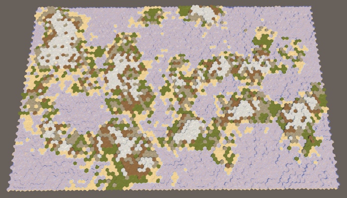
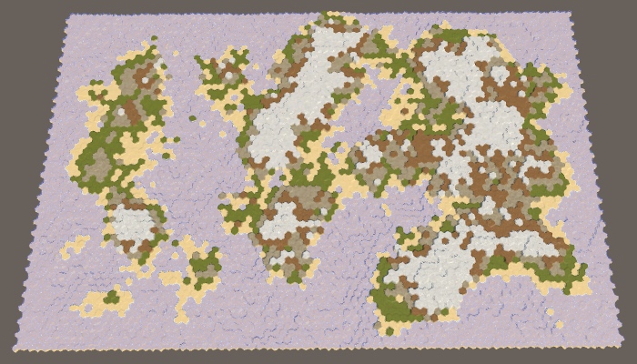
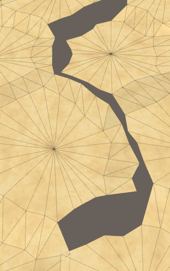
The borders of the map are 0 × 0, 5 × 5, 10 × 10 and 0 × 10.
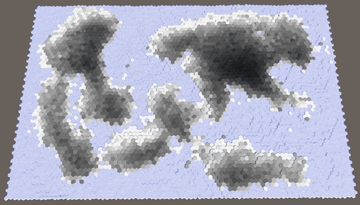
When all parameters of the map are set to default values, the border of size 5 will reliably protect the edge of the map from touching the land. However, this is not guaranteed. Drying can sometimes come close to the edge, and sometimes touch it in several places.
The likelihood that land will cross the entire border depends on the size of the border and the maximum size of the site. Without hesitation, areas remain hexagons. Full hexagon with radius contains cells If there are hexagons with a radius equal to the size of the border, then they will be able to cross it. A full hexagon with a radius of 5 contains 91 cells. Since the default maximum is 100 cells per plot, this means that the land will be able to pave a bridge across 5 cells, especially if there are fluctuations. To prevent this from happening, either reduce the maximum size of the area or increase the size of the border.
To see this more clearly, we can set the border size to 200. Since the full hexagon with a radius of 8 contains 217 cells, the land will most likely touch the edge of the map. At least, if you use the default border size value (5). Increasing the boundary to 10 will greatly decrease the probability.

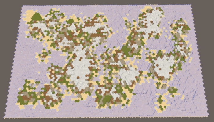
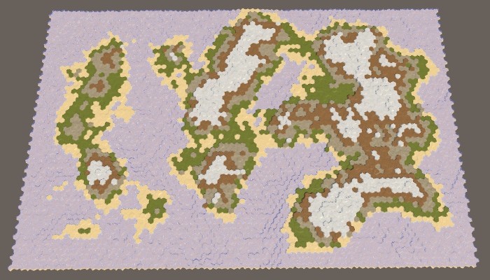
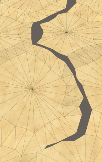
The land area has a constant size of 200, the boundaries of the map are 5 and 10.
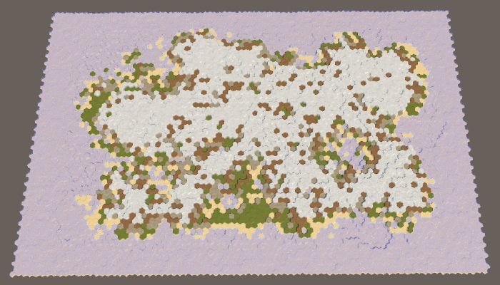
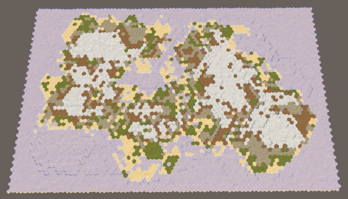
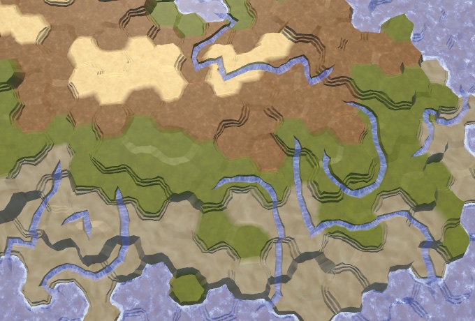
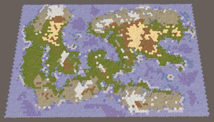
Note that by increasing the border of the map and maintaining the same percentage of land, we force the land to form a smaller area. As a result, a large default map is likely to create a single large mass of land — the supercontinent Pangea — possibly with several small islands. With an increase in the size of the border, the probability of this increases, and at certain values, we are almost guaranteed to get the supercontinent. However, when the percentage of land is too large, most of the available areas are filled and as a result we get an almost rectangular mass of land. To avoid this, you need to reduce the percentage of land.
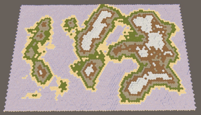
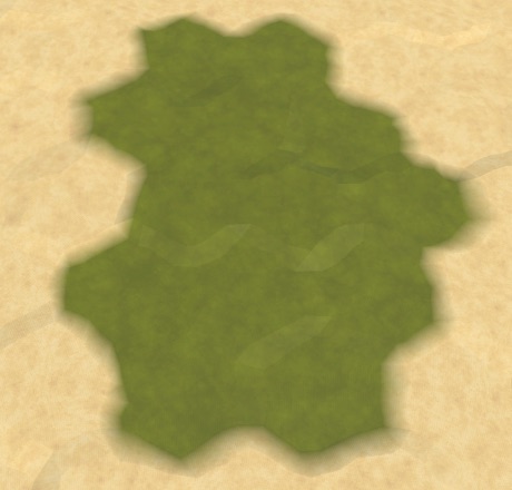
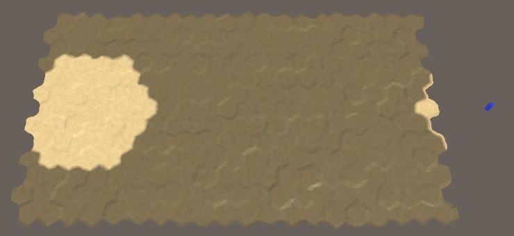
40% sushi with border cards 10.
We generate the right amount of land, simply continuing to raise the land until we reach the desired land mass. It works, because sooner or later we will raise each cell on the water level. However, when using the border of the map, we cannot reach every cell. When a very high percentage of land is required, it will lead to endless "attempts and failures" of the generator to raise more land, and it will get stuck in an endless cycle. The application will freeze, but this should not happen.
We cannot reliably find impossible configurations in advance, but we can protect ourselves from infinite loops. We will simply track the number of cycles executed in
For a large map, a value of a thousand iterations seems acceptable, and ten thousand iterations already seem absurd. So let's use this value as the end point.
If we get a spoiled map, then performing 10,000 iterations will not take much time, because many cells will quickly reach their maximum height, which will prevent new areas from growing.
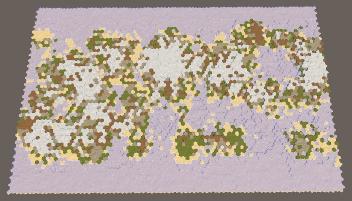
Even after interrupting the cycle, we still get the right map. It just does not have the right amount of sushi and it will not look very interesting. Let's display a notification to the console, informing us of the remaining amount of land we could not spend.
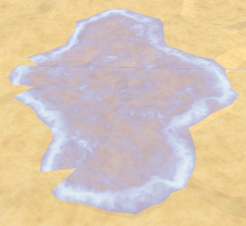
95% of the land with a border of 10 cards could not spend the entire amount.
unitypackage
Now that we have a map boundary, we essentially divided the map into two separate regions: the region of the border and the region of creation of the plots. Since only the region of creation is important for us, we can consider such a situation as a situation with one region. The region simply does not cover the entire map. But if this is not possible, then nothing prevents us from dividing the map into several unconnected regions of land creation. This will allow land masses to form independently of each other, denoting different continents.
Let's start by describing one region of the map as a struct. This will make it easier for us to work with several regions. For this we create a
For everything to work, we need to add the
And also in
To support multiple regions, replace one
At this stage, it would be nice to add a separate method for creating regions. It must create the desired list or clear it if it already exists. After that, it will identify one region, as we did before, and add it to the list.
Let's call this method in
In order for
Now the
The
However, we still need to do so that the lowering of the plots is distributed evenly. This can be done while deciding for all regions whether to lower them.
Finally, to use exactly the entire amount of land, we need to stop the process as soon as the amount reaches zero. This can occur at any stage of the region's cycle. Therefore, we move the check to zero amount in the inner loop. In fact, we can perform this check only after raising land, because when lowering the amount is never spent. If we are done, we can immediately exit the
Although we now have the support of several regions, we still ask only one. Let's change
Generating maps at this stage will not make any difference. Although we have defined two regions, they occupy the same region as one old region. To separate them to the side, you need to leave between them an empty space. This can be done by adding a region border slider, using the same interval and default value as for the map borders.

Slider border region.
Since the land can be formed on either side of the space between the regions, the probability of creating bridges from land at the edges of the map will increase. To prevent this, we use the region's border to set the land-free zone between the dividing line and the area in which the plots can begin. This means that the distance between neighboring regions is two more than the size of the border of the region.
To apply this region boundary, subtract it from the

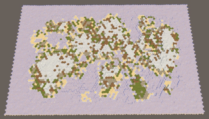
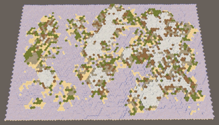
The map is divided vertically into two regions.
With the default parameters, two noticeably separated regions will be created, however, as in the case of one region and a large map boundary, we are not guaranteed to get exactly two land masses. Most often it will be two large continents, possibly with several islands. But sometimes two or more large islands can be created in a region. And sometimes two continents can be connected by an isthmus.
Of course, we can also split the map horizontally by changing the approaches for measuring X and Z. Let's randomly choose one of two possible orientations.

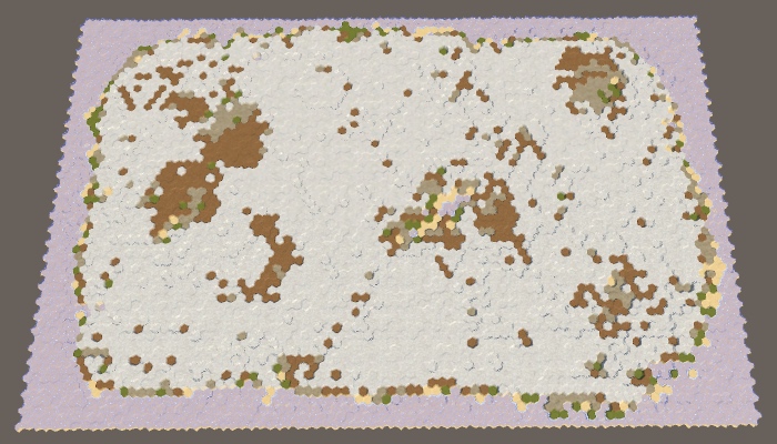
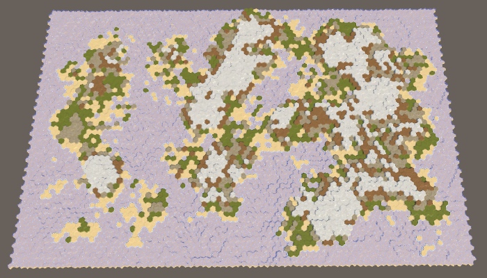
Map horizontally divided into two regions.
Since we use a wide map, with horizontal separation, wider and thinner regions will be created. As a result, these regions are more likely to form several divided land masses.
Let's make the number of regions customizable, create support from 1 to 4 regions.

Slider for the number of regions.
We can use the
Three regions are like two, only thirds are used instead of half. In this case, the horizontal separation will create too narrow regions, so we created support only for the vertical separation. Notice that as a result we have double the space of the region’s border, therefore there is less space for creating new sites than in the case of two regions.
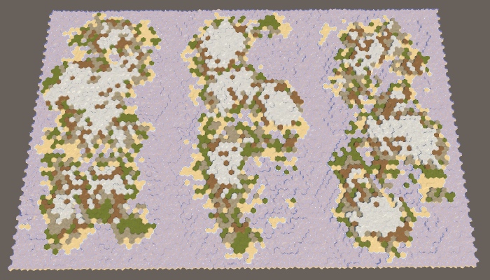
Three regions.
Four regions can be created by combining horizontal and vertical divisions and adding one region to each corner of the map.
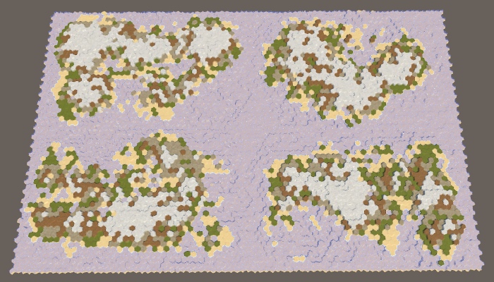
Four regions.
The approach used here is the simplest way to split a card. It generates approximately the same land mass in terms of mass, and their variability is controlled by other map generation parameters. However, it will always be pretty obvious that the map was divided along straight lines. The more control we need, the less organic the result will look. Therefore, it is normal if you need approximately equal regions for gameplay. But if you need the most variable and unlimited land, you will have to make it with the help of one region.
In addition, there are other ways to split a map. We can not be limited to straight lines. We are not even obliged to use regions of the same size, as well as cover the entire map with them. We can leave holes. You can also allow the intersection of regions or change the distribution of land between regions. You can even set your own generator parameters for each region (although this is more difficult), for example, so that both a large continent and an archipelago are on the map.
unitypackage
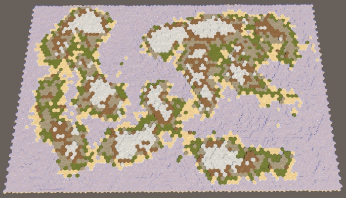
So far, all the cards we generated looked pretty rough and broken.The real relief may look like this, but over time it becomes smoother and smoothed, its sharp parts become dull due to erosion. To improve the maps, we can apply this process of erosion. We will do this after creating coarse sushi, in a separate method.
The more time passes, the more erosion appears. Therefore, we want erosion to be not permanent, but customizable. At a minimum, erosion is zero, which corresponds to the maps created earlier. At maximum, erosion is comprehensive, that is, the further application of erosion forces will no longer change the relief. That is, the erosion parameter should be a percentage from 0 to 100, and by default we take 50.

Slider erosion.
Erosion makes the relief smoother. In our case, the only sharp parts are the cliffs. Therefore, the purpose of the erosion process will be they. If a precipice exists, erosion should reduce it, until it eventually turns into a slope. We will not smooth the slopes, because it will lead to dull relief. To do this, we need to determine which cells are on the tops of the cliffs, and reduce their height. These will be erosion prone cells.
Let's create a method that determines whether a cell can be subject to erosion. He determines this by checking the neighbors of the cell until he finds a large enough height difference. Since the cliffs need a difference of at least one or two levels of height, the cell is prone to erosion if one or several of its neighbors are at least two steps below it. If there is no such neighbor, the cell cannot be eroded.
We can use this method to
As soon as we know the total number of erosion-prone cells, we can use the percentage of erosion to determine the number of remaining erosion-prone cells. For example, if the percentage is 50, then we must subject the cells to erosion, until half of the original amount remains. If the percentage is 100, then we will not stop until we destroy all erosion prone cells.
Let's start with a naive approach and assume that simply lowering the height of a cell destroyed by erosion will make it no longer prone to erosion. If this were true, then we could just take random cells from the list, lower their height, and then remove them from the list. We would repeat this operation until we reach the required number of eroded cells.
To prevent the search required

A naive decrease in 0% and 100% erosion-prone cells, seed cards 1957632474.
Our naive approach allows us to apply erosion, but not to the necessary extent. This happens because the cell can still remain subject to erosion after one drop in height. Therefore, we will remove a cell from the list only when it is no longer subject to erosion.

100% erosion while maintaining the erosion-prone cells in the list.
So we get much more erosion, but using 100%, we still do not get rid of all the cliffs. The reason is that after reducing the height of the cell, one of its neighbors may become eroded. Therefore, as a result, we may have more erosion prone cells than was originally.
After lowering the cell, we need to check all its neighbors. If now they are subject to erosion, but they are not yet in the list, then you need to add them there.

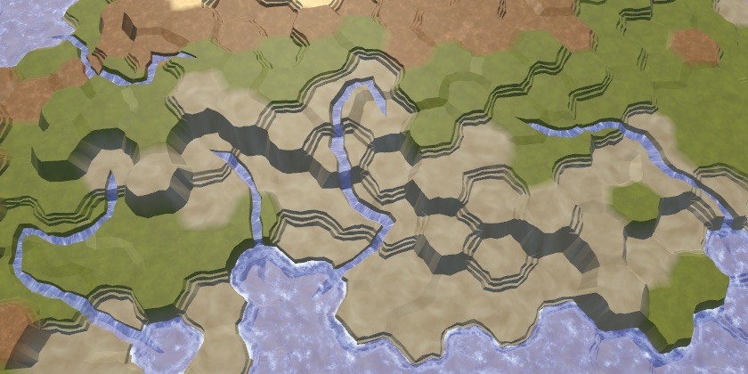
All erosion prone cells are omitted.
Now the process of erosion can continue until all the cliffs disappear. This significantly affects the land. Most of the land mass disappeared and we got a much smaller percentage of the land needed. It happened because we remove land from the map.
True erosion does not destroy matter. She takes her from one place and places her somewhere else. We can do the same. By dropping one cell, we have to pick up one of its neighbors. In fact, one level of height is transferred to a lower cell. This saves the total amount of map heights, while simply smoothing it out.
To realize this, we need to decide where to move the products of erosion. This will be our target point of erosion. Let's create a method to determine the target point of the cell that will be eroded. Since this cell contains a break, it will be logical to select a cell under this break as a target. But a cell prone to erosion may have several cliffs, so check all the neighbors and put all candidates on a temporary list, and then we will choose one of them randomly.
In
Since we raised the target cell, part of the neighbors of this cell may cease to be subject to erosion. It is necessary to bypass them and check whether they are subject to erosion. If not, but they are in the list, then you need to remove them from it.
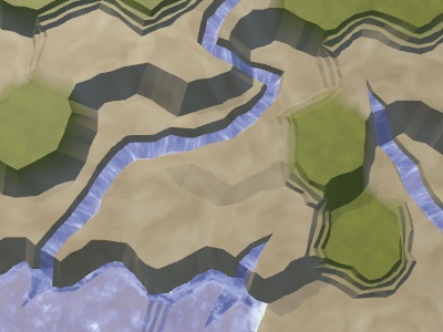
100% erosion preserving the mass of land.
Now, erosion can smooth out the relief much better, lowering some areas and raising others. As a result, the mass of land can both increase and narrow. This may change the percentage of land on a few percent in one direction or another, but serious deviations rarely occur. That is, the more erosion we apply, the less control we will have over the resulting percentage of land.
Although we do not need to worry about the effectiveness of the erosion algorithm, it is possible to make simple improvements to it. First, note that we are explicitly checking whether the cell we have eroded can be eroded. If not, then essentially we remove it from the list. Therefore, you can skip checking this cell when traversing the neighbors of the target cell.
Secondly, we only needed to check the neighbors of the target cell when there was a break between them, but now it is not necessary. This happens only when the neighbor is now one step higher than the target cell. If this is so, then the neighbor is guaranteed to be on the list, so we don’t need to check it, that is, we can skip an unnecessary search.
Thirdly, we can use a similar trick when checking the neighbors of an erosion-prone cell. If there is a cliff between them now, then the neighbor is subject to erosion. To find out, we do not need to call
However, we still need to check whether the target cell is prone to erosion, but the cycle shown above no longer does this. Therefore, we do this explicitly for the target cell.
Now we can apply erosion rather quickly and to the desired percentage relative to the initial number of generated cliffs. Note that due to the fact that we slightly changed the place in which the target cell is added to the list of erosion-prone, the result has slightly changed compared to the result before optimizations.
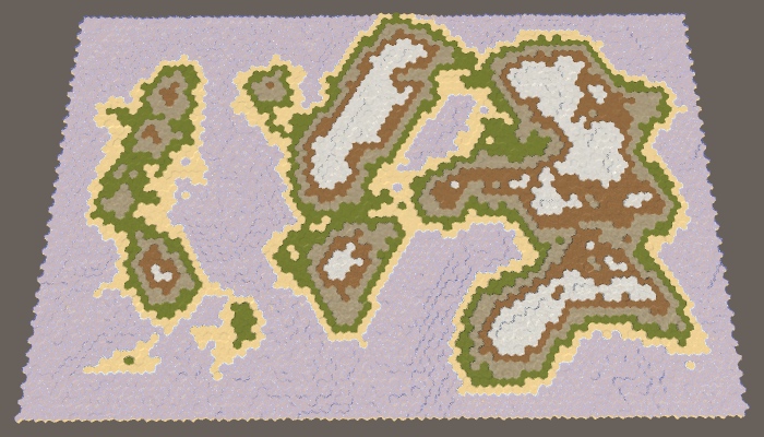
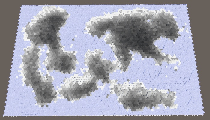
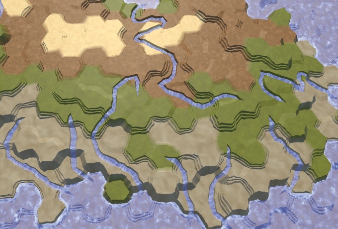
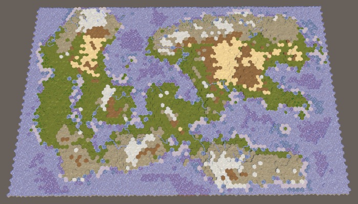
25%, 50%, 75% and 100% erosion.
Also note that despite the changed shape of the coast, the topology has not fundamentally changed. Sushi masses usually remain either connected or separated. Only small islands can drown completely. The relief details are smoothed out, but the general shapes remain the same. A narrow connection may disappear, or grow slightly. A small space can fill up or expand slightly. Therefore, erosion will not strongly glue the separated regions.

The four fully eroded regions still remain separate.
unitypackage
In this part we will add moisture on land.
This tutorial was created in Unity 2017.3.0.
Use the water cycle to determine the biomes.
Up to this point, the map generation algorithm changed only the height of the cells. The biggest difference between cells was whether they were above or under water. Although we can set different types of terrain, this is just a simple visualization of the height. It will be better to set the types of relief, given the local climate.
Earth's climate is a very complex system. Fortunately, we do not need to create a realistic climate simulation. We will need something that looks natural enough. The most important aspect of climate is the water cycle, because for survival the flora and fauna need liquid water. Temperature is also very important, but for now we will focus on water, essentially leaving the global temperature constant and changing only the humidity.
The water cycle describes the movement of water around the environment. Simply put, the reservoirs evaporate, which creates clouds that shed rain, which again flows into the reservoirs. The system has many more aspects, but simulations of these stages may already be enough to create a natural-looking distribution of water on the map.
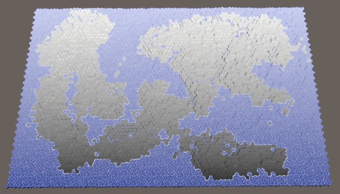
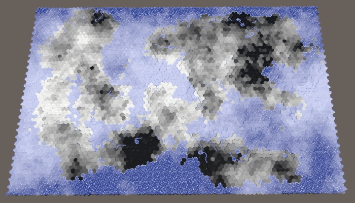
Before we move on to this simulation, it will be helpful to directly see the relevant data. To do this, we change the shader the Terrain . Add a switchable property to it, which can be switched to data visualization mode, which displays raw map data instead of ordinary relief textures. This can be implemented using float-properties with a switchable attribute that specifies the keyword. Due to this, it will appear in the material inspector as a checkbox that controls the task of the keyword. The name of the property itself is not important, we are only interested in the keyword. We use SHOW_MAP_DATA .
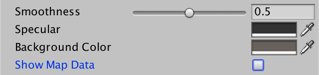
Switch to display the map data.
Add a shader function to enable keyword support.
We will make it so that one float value is displayed, as is the case with the rest of the relief data. To do this, we will add a
In the vertex program, we use the Z channel of the cell data to fill
When you need to display the data of the cells, use them directly as an albedo fragment instead of the usual color. Multiply it by the grid so that the grid is still enabled when rendering data.
To actually pass the data to the shader. we need to add to the
However, this decision affects the research system. The value of 255 blue channel data is used to indicate that cell visibility is in transition. In order for this system to continue to work, we need to use as a maximum the byte value of 254. Note that the movement of the detachment will erase all the card data, but this suits us, because they are used for debugging card generation.
Add a method with the same name and in
To test the code, we change it
Now we can switch between regular terrain and data visualization using the Show Map Data checkbox of the asset of the Terrain material .

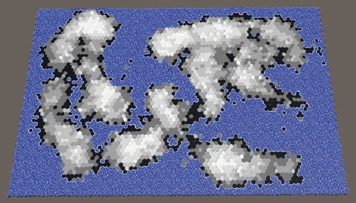
Map 1208905299, the usual relief and visualization of heights.
To simulate climate, we need to track climate data. Since the map consists of discrete cells, each of them has its own local climate. Create a structure
Add a list to track climate data for all cells.
Now we need a method for creating a climate map. It should begin by clearing the list of climatic zones, and then add one item for each cell. The climate data is simply zero, this can be achieved using a standard constructor
The climate should be created after the impact on the land of erosion before specifying the types of relief. In reality, erosion is mainly caused by the movement of air and water, which are part of the climate, but we will not simulate it.
Modify
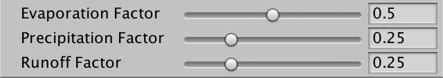
The first stage of the climate simulation is evaporation. How much water should evaporate? Let's control this value with the slider. A value of 0 means no evaporation, 1 means maximum evaporation. By default we use 0.5.
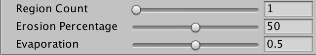
Evaporation slider.
Let's create another method specifically for forming a single cell climate. We give it the cell index as a parameter and use it to get the corresponding cell and its climate data. If the cell is under water, then we are dealing with a reservoir that must evaporate. We immediately turn steam into clouds (ignoring dew points and condensation), so we directly add evaporation to the value of the cell clouds. Finished with this, copy the climate data back to the list.
Call this method for each cell in
But this is not enough. To create a complex simulation, we need to form a climate of cells several times. The more often we do this, the better the result will be. Let's just pick a constant value. I use 40 cycles.
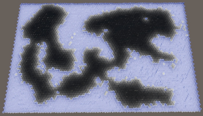
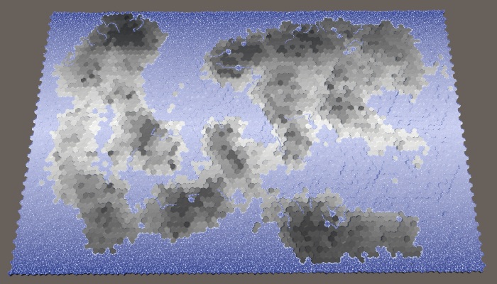
Since for the time being we only increase the value of the clouds above the cells filled with water, as a result we will have black land and white water bodies.

Evaporation above water.
Clouds are not constantly in one place, especially when more water evaporates. The difference in pressure causes the air to move, which manifests itself in the form of wind, which also forces the clouds to move.
If there is no dominant wind direction, then on average the clouds of cells will evenly disperse in all directions, finding themselves in neighboring cells. When generating new clouds in the next cycle, let's distribute all the clouds in a cell, according to its neighbors. That is, each neighbor gets one sixth of the cell clouds, after which there is a local decrease to zero.
To actually add clouds to your neighbors, you need to go around them in a loop, get their climate data, increase the value of the clouds and copy them back to the list.

Scattering clouds.
At the same time, an almost white map is created, because at each cycle underwater cells add more and more clouds to the global climate. After the first cycle, land cells next to the water will also have clouds that need to be dispersed. This process continues until most of the map is covered with clouds. In the case of the map 1208905299 with default parameters, only the inner part of a large land mass in the northeast remained completely uncovered.
Note that reservoirs can generate an infinite amount of clouds. The water level is not part of the climate simulation. In reality, water bodies are saved only because water flows back into them approximately at the rate of evaporation. That is, we simulate only a partial water cycle. This is normal, but we need to understand that the longer the simulation is performed, the more water is added to the climate. So far, water is lost only at the edges of the map, where scattered clouds are lost due to the absence of neighbors.
You can see the loss of water at the top of the map, especially in the cells at the top right. In the last cell there are no clouds at all, because it remains the last in which the climate is formed. She has not yet received from the neighbor of the clouds.
Water does not stay in a cold state forever. At some point, she must fall to the ground again. This usually happens in the form of rain, but sometimes it can be snow, hail or sleet. All this is generally called precipitation. The magnitude and speed of the disappearance of clouds vary greatly, but we simply use a custom global precipitation coefficient. A value of 0 means no precipitation, a value of 1 means that all clouds disappear instantly. The default is 0.25. This means that in each cycle a quarter of the clouds will disappear.

Rainfall slider.
We will simulate precipitation after evaporation and before scattering of clouds. This will mean that part of the water evaporated from water bodies immediately precipitates, so the number of scattering clouds decreases. Over land, precipitation will lead to the disappearance of clouds.
Fading clouds.
Now that we are destroying 25% of the clouds in each cycle, the land has again become almost black. Clouds manage to move only a few steps deep into the land, after which they become imperceptible.
unitypackage
Although precipitation destroys clouds, they should not remove water from the climate. After falling to the ground, water is saved, only in a different state. It can exist in many forms, which we will generally consider humidity.
We are going to improve the climate model by tracking two states of water: clouds and humidity. To implement this, add to the
In its most generalized form, evaporation is the process of converting moisture into clouds, at least in our simple climate model. This means that evaporation should not be a constant value, but another factor. Therefore, we perform a refactoring-rename
When the cell is under water, we simply declare that the humidity level is 1. This means that the evaporation is equal to the evaporation coefficient. But now we can also get evaporation from sushi cells. In this case, we need to calculate the evaporation, subtract it from the humidity and add the result to the clouds. After that, precipitation is added to the humidity.
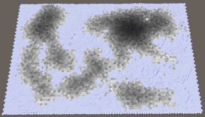
Since the clouds are now supported by evaporation from over land, we can move them further inland. Now the bulk of the land has become gray.

Clouds with evaporation of humidity.
Let's change it

Moisture display.
At this stage, the humidity looks quite similar to the clouds (except that all the underwater cells are white), but this will change soon.
Evaporation is not the only way moisture can leave a cell. The water cycle tells us that the main part of the moisture added to the land somehow turns out to be in the water bodies again. The most visible process is the flow of water over land under the influence of gravity. We will not simulate real rivers, but use a custom coefficient for rainfall runoff. It will denote the percentage of water flowing to the lower areas. Let's default drain will be equal to 25%.
Drain slider.
Water flow acts as a scattering of clouds, but with three differences. First, not all moisture is removed from the cell. Secondly, it carries moisture, not clouds. Thirdly, he descends, that is, only to neighbors with a lower height. The runoff coefficient describes the amount of humidity that would pour out of the cell if all the neighbors were lower, but often they are less. This means that we will reduce the humidity of the cell only when we find a neighbor below.
Water flowing to a lower height.
As a result, we have a more varied moisture distribution, because high cells transfer their moisture to the lower ones. We also see much less moisture in the coastal cells, because they drain the moisture into the underwater cells. To weaken this effect, we also need to use the water level when determining whether the cell is lower, that is, to take the apparent height.
Use the visible height.
Water not only flows down, it spreads, seeping through the level relief, and is absorbed by land adjacent to water bodies. This effect may have a minor effect, but it is useful for smoothing the distribution of moisture, so let's add it to the simulation. Create it with your own customizable coefficient, the default is 0.125.
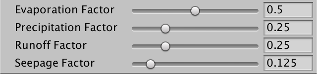
Penetration slider.
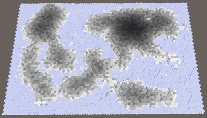
The leakage is similar to the drain, except that it applies when the neighbor has the same apparent height as the cell itself.

Added a bit of trickle down.
unitypackage
Although we have already created a decent simulation of the water cycle, it does not look very interesting, because there are no rain shadows in it that most clearly demonstrate climatic differences. Rain shadows are areas in which there is a significant lack of precipitation compared to neighboring areas. Such areas exist because mountains make it difficult for the clouds to reach them. To create them requires high mountains and the dominant wind direction.
Let's start by adding the dominant wind direction to the simulation. Although the dominant wind directions on the surface of the Earth vary greatly, we will manage a custom global wind direction. Let's use northwest by default. In addition, let's make the wind power adjustable from 1 to 10 with a default value of 4.

Wind direction and strength.
The strength of the dominant wind is expressed relative to the total dispersion of clouds. If the wind force is 1, then the scattering is the same in all directions. When it is 2, the scattering is two higher in the direction of the wind than in other directions, and so on. We can accomplish this by changing the divisor in the cloud scattering formula. Instead of six, it will be five plus wind power.
In addition, the wind direction determines the direction from which the wind blows. Therefore, we need to use the opposite direction as the main direction of scattering.
Now we can check whether the neighbor is in the main direction of scattering. If so, then we must multiply the scattering of clouds by the force of the wind.

North-west wind, force 4.
The dominant wind adds the direction of the distribution of humidity over land. The stronger the wind, the more powerful the effect becomes.
The second ingredient in getting rain shadows is mountains. We do not have a strict classification of what is a mountain, as there is no nature. Only absolute height is important. In fact, when the air moves over the mountain, it is forced to rise, cools and may contain less water, which leads to precipitation before the air passes over the mountain. As a result, on the other side we get dry air, that is, a rain shadow.
Most importantly, the higher the air rises, the less water it can contain. In our simulation, we can imagine this as a forced restriction of the maximum cloud value for each cell. The higher the apparent height of the cell, the lower this maximum should be. The easiest way to do this is to set the maximum to 1 minus the apparent height divided by the maximum height. But in fact, let's divide by a maximum of minus 1. This will allow a small fraction of the clouds to make their way even through the highest cells. We assign this maximum after calculating the precipitation and before scattering.
If, as a result, we get more clouds than acceptable, then simply convert the excess clouds to humidity. In fact, this is how we add additional rainfall, as it happens in real mountains.

Rain shadows caused by high altitude.
unitypackage
At this stage, we already have quite high-quality partial simulation of the water cycle. Let's tidy it up a little, and then apply it to determine the type of cell relief.
As mentioned earlier under the spoiler, the cell formation order affects the result of the simulation. Ideally, this should not be and in fact we form all the cells in parallel. This can be done by applying all changes of the current stage of formation to the second climate list
Clean up and initialize this list, like everyone else. Then we will exchange lists on each cycle. The simulation will alternately use two lists and apply current and following climate data.
When a cell affects the climate of its neighbor, we must change the following climate data, not the current one.
And instead of copying the following climate data back to the current climate list, we get the following climate data, add current humidity to it and copy it all into the following list. After that, reset the data in the current list so that it is updated for the next cycle.
While we are doing this, let's also assign a maximum of 1 to the humidity level so that the land cells could not be more wet than the underwater ones.
Parallel computations.
There is a possibility that as a result of the simulation too much dry land will appear, especially with a high percentage of land. To improve the picture, we can add a customizable initial moisture level with a default value of 0.1.

At the top of the slider is the original moisture.
Use this value for the humidity of the original climate list, but not for the following.

With initial moisture.
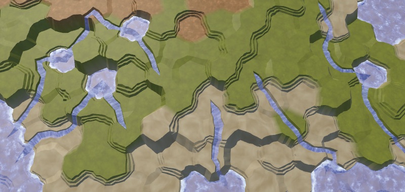
We conclude by using humidity instead of height to specify the type of cell topography. Let's use snow for completely dry sushi, use snow for dry regions, then there is a stone, grass for wet enough, and land for water-soaked and underwater cells. The easiest way to use five intervals in increments of 0.2.

Biomes
When using a uniform distribution, the result is not very good, and it looks unnatural. It is better to use other thresholds, such as 0.05, 0.12, 0.28 and 0.85.
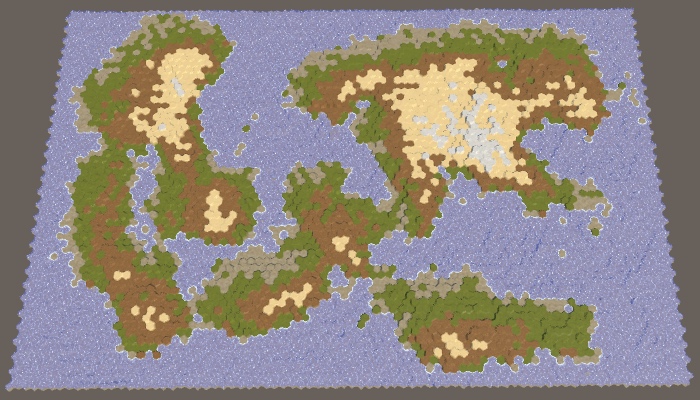
Modified biomes.
unitypackage
In this part we will supplement the water cycle with rivers and temperature, and also assign more interesting biomes to the cells.
Tutorial was created using Unity 2017.3.0p3.
Heat and water enliven the map.
Rivers are a consequence of the water cycle. In fact, they are formed by drains that are pulled out with the help of erosion of the channel. This implies that you can add rivers based on the value of the sinks of the cells. However, this does not guarantee that we will get something resembling real rivers. When we start the river, it will have to flow as far as possible, potentially through a multitude of cells. This is not consistent with our simulation of the water cycle, which processes cells in parallel. In addition, it is usually necessary to control the number of rivers on the map.
Since the rivers are very different, we will generate them separately. We use the results of a simulation of the water cycle to determine the location of the rivers, but the rivers in turn will not affect the simulation.
On our maps, the cell may or may not have a river. In addition, they can branch or join. In reality, rivers are much more flexible, but we will have to get by with this approximation, creating only large rivers. The most important thing is that we need to determine the place where the big river starts, which is chosen randomly.
Since rivers require water, the source of the river must be in a cell with high humidity. But this is not enough. Rivers flow down the slopes, so ideally the source should have a great height. The higher the cell above the water level, the better candidate it is for the source of the river. We can visualize this as map data, dividing the height of the cell by the maximum height. To get the result relative to the water level, we will subtract it from both heights before dividing.
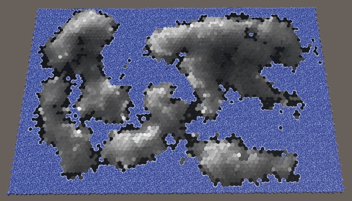
Humidity and altitude above water level. Large map number 1208905299 with default parameters.
The best candidates are those cells that have both high humidity and high altitude. We can combine these criteria by multiplying them. The result will be the value of fitness or weight for the source of the rivers.
Weights for sources of the rivers.
Ideally, we would use these weights to reject the random selection of the source cell. Although we can create a list with the right weights and choose from it, this is a non-trivial approach and it slows down the generation process. A simpler classification of significance divided into four levels will be sufficient for us. The first candidates will be weights with values higher than 0.75. Good candidates have weights from 0.5. Eligible candidates - more than 0.25. All other cells are discarded. Let's show how it looks graphically.

Categories of the weights of the origins of the rivers.
With such a classification scheme, we will most likely get rivers with sources in the highest and humid areas of the map. But nevertheless, the likelihood of creating rivers in relatively dry or low areas is preserved, which increases variability.
Add a method
This method should be called after
After completing the classification, you can get rid of the visualization of its data on the map.
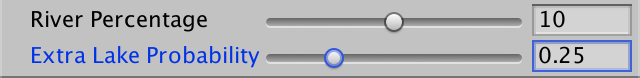
How many rivers do we need? This parameter must be customizable. Since the length of the rivers varies, it will be more logical to control it with the help of river points, which determine the number of land cells in which the rivers should be contained. Let's express them as a percentage with a maximum of 20% and a default value of 10%. Like the percentage of land, this is a target value, not a guaranteed one. As a result, we may have too few candidates or rivers that are too short to cover the required amount of land. That is why the maximum percentage should not be too large.

Slider percentage of rivers.
To determine river points, expressed as the number of cells, we need to memorize how many land cells were generated in
Inside the
Next, we continue to take and remove random cells from the original list, while we still have points and source cells. In case of completion of the number of points we will display a warning in the console.
In addition, we will add a method for directly creating rivers. As a parameter, it needs the source cell, and after completion it must return the length of the river. We start with the procurement method, which returns zero length.
Call this method at the end of the loop we just added in
It is logical to create a river flowing to the sea or another reservoir. When we start from the source, we immediately get the length 1. After that we choose a random neighbor and increase the length. We continue to move until we reach the underwater cell.
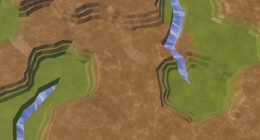
Random rivers.
As a result of this naive approach, we get randomly scattered fragments of rivers, mainly due to the replacement of previously generated rivers. This can even lead to errors, because we do not check whether the neighbor actually exists. We need to check all directions in the loop and make sure that there is a neighbor there. If there is one, then we add this direction to the list of potential flow directions, but only if a river does not flow through this neighbor. Then select a random value from this list.
With this new approach, we may have zero flow directions available. When this happens, the river can no longer flow further and must be completed. If at this moment the length is 1, then this means that we could not flow out of the source cell, that is, there can be no river at all. In this case, the length of the river is zero.
Preserved rivers.
Now we keep the already created rivers, but we still may receive isolated fragments of rivers. This is because while we ignored the height. Every time we forced the river to flow to a greater height,
Rivers flowing down.
So we will get rid of many fragments of the river, but some still remain. From this moment, getting rid of the most ugly rivers becomes a matter of refinement. To begin with, rivers prefer to flow down as quickly as possible. They will not necessarily choose the shortest possible route, but the likelihood of this is high. To imitate this, the directions down we add to the list three times.
In addition to flowing down, water also has inertia. A river is more likely to flow straight or slightly curved than it makes a sudden sharp turn. We can add such distortion by tracking the last direction of the river. If the potential flow direction does not deviate too far from this direction, then we add it to the list again. This is not a problem for the source, so we will just always add it again.
This greatly reduces the likelihood of re-zigzags that look ugly.
Fewer sharp turns.
Sometimes it turns out that the river flows right next to the source of the previously created river. If the source of this river is not at a higher altitude, then we can decide that the new river flows into the old one. As a result, we get one long river, not two adjacent ones.
To do this, we will pass the neighbor, only if it has an incoming river, or if it is the source of the current river. Having determined that this direction is not up, we check if there is an outgoing river there. If there is, then we again found the old river. Since this happens quite rarely, we will not check other neighboring sources and immediately unite the rivers.

Rivers before and after combining.
Since good candidates for the source are usually a bunch of hands together, we will have clusters of rivers. In addition, we may have rivers that take the source directly next to the reservoir, as a result of which rivers of length 1 will arise. We can distribute the sources, discarding those that are located next to the river or reservoir. We do this by circumventing the neighbors of the selected source in a loop inside
And although the rivers will still flow next to each other, they tend to cover a large area.

Without and with the saved distance.
Not all rivers reach the reservoir, some get stuck in the valleys or blocked by other rivers. This is not a particular problem, because often real rivers also seem to disappear. This can happen, for example, if they flow underground, disperse in swampy areas or dry out. Our rivers cannot visualize this, so they simply end.
However, we can try to minimize the number of such cases. Although we cannot unite the rivers or force them to flow upwards, we can make them end in lakes, which is often found in reality and looks good. For this
If we are stuck, first of all we need to check whether we are still in the source. If yes, then just cancel the river. Otherwise, we check if all the neighbors are at least as high as the current cell. If so, then we can raise the water to this level. This will create a lake from a single cell, unless the height of the cell remains at the same level. If so, then simply assign the height one level below the water level.

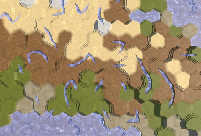
The ends of the rivers without lakes and with lakes. In this case, the percentage of rivers is equal to 20.
Notice that now we can have underwater cells that are above the water level used when generating the map. They will denote lakes above sea level.
We can also create lakes even if we are not stuck. In this case, the river can flow, flowing and flowing from the lake. If we are not stuck, the lake can be created by raising the water level of the current height of the cell, and then reducing the height of the cell. This is applicable only when the minimum height of the neighbor is at least equal to the height of the current cell. We do this at the end of the river cycle and before moving to the next cell.
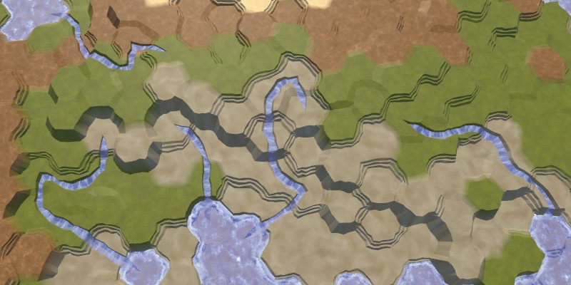
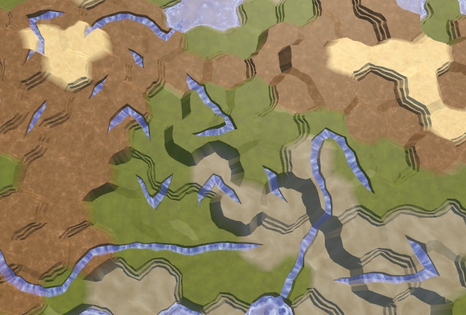
Without and with additional lakes.
Several lakes are beautiful, but without limitations we can create too many lakes. So let's add a custom probability for additional lakes, the default value of 0.25.
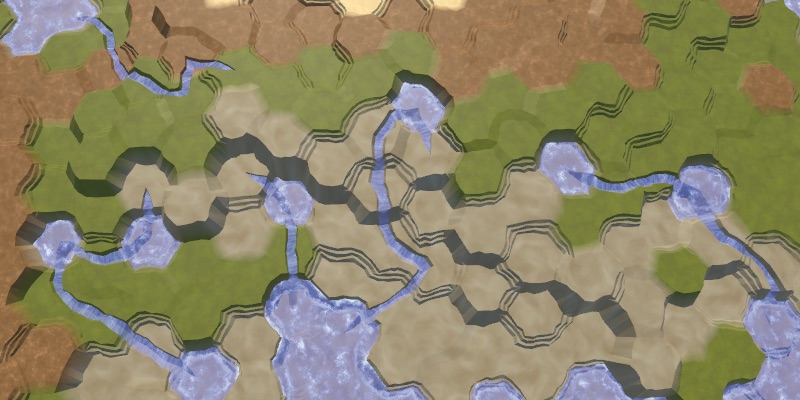
It will control the likelihood of generating an additional lake, if possible.
Additional lakes.
unitypackage
Water is only one of the factors that can determine the biome of a cell. Another important factor is temperature. Although we can simulate the course and diffusion of temperatures like a simulation of water, to create an interesting climate we need only one complex factor. Therefore, we will keep the temperature simple and will set it for each cell.
The latitude is most affected by temperature. It is hot at the equator, cold at the poles, and there is a smooth transition between them. Let's create a method
Determine the temperature in
Latitude as temperature, southern hemisphere.
We get a linear temperature gradient increasing from bottom to top. You can use it to simulate the southern hemisphere, with the pole below and the equator above. But we do not need to describe the entire hemisphere. Using a smaller temperature difference or no difference at all, we can describe a smaller area. To do this, we will make low and high temperatures customizable. We set these temperatures in the range of 0–1, and use the extreme values as default values.
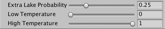
Temperature sliders.
Apply the temperature range using linear interpolation, using latitude as the interpolator. Since we express latitude as a value from 0 to 1, we can use
Note that low temperatures are not necessarily lower than high temperatures. If desired, you can flip them.
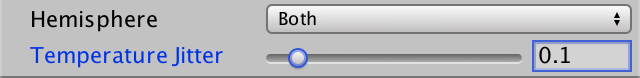
Now we can model the southern hemisphere, and possibly the northern one, if we reverse the temperatures. But it is much more convenient to use a separate configuration option to switch between the hemispheres. Let's create an enumeration and a field for it. Thus, we will also add the option to create both hemispheres, which is applicable by default.
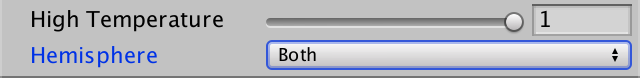
The choice of the hemisphere.
If we need the northern hemisphere, we can simply flip the latitude, subtracting it from 1. To simulate both hemispheres, the poles must be below and above the map, and the equator should be in the middle. You can do this by doubling the latitude, while the lower hemisphere will be processed correctly, and the upper one will have a latitude from 1 to 2. To fix this, we will subtract the latitude from 2 when it exceeds 1.

Both hemispheres.
It is worth noting that this makes it possible to create an exotic map in which the equator is cold and the poles are warm.
In addition to latitude, the height also noticeably affects the temperature. On average, the higher we climb, the colder it gets. We can turn this into a factor, as we did with the candidates of the rivers. In this case, we use the height of the cell. In addition, this indicator decreases with height, that is, it is equal to 1 minus the height divided by the maximum relative to the water level. So that the indicator at the highest level does not fall to zero, we add to the divisor. Then we use this indicator to scale the temperature.
Height affects temperature.
We can make the simplicity of the temperature gradient less noticeable by adding random temperature variations. A small chance to make it more realistic, but with too large fluctuations, they will look arbitrary. Let's make the temperature fluctuation force adjustable and express it as the maximum temperature deviation with a default value of 0.1.
Temperature slider.
Such oscillations should be smooth with small local changes. For this you can use our noise texture. We will call
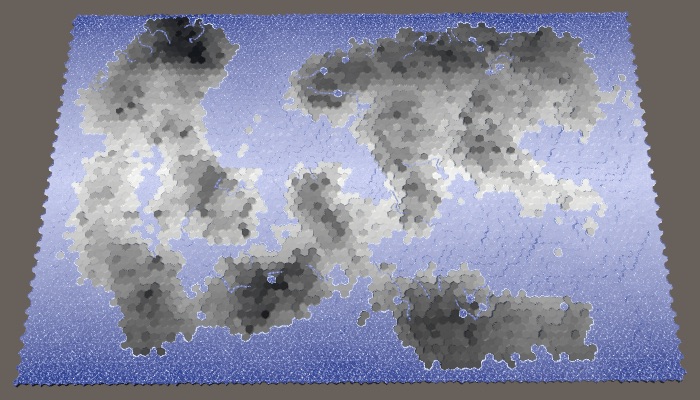
Temperature fluctuations with values of 0.1 and 1.
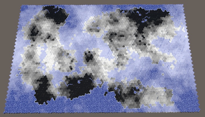
We can add a little variation to each map to fluctuations, choosing random noise from four channels. Set the channel once in
Different temperature fluctuations with maximum power.
unitypackage
Now that we have data on humidity and temperature, we can create a matrix of biomes. By indexing this matrix, we can assign all cells to the biome, creating a more complex landscape than using only one dimension of the data.
There are many climate models, but we will not use any of them. We will make it very simple, we are only interested in consistency. Dry means desert (cold or hot), for it we use sand. Cold and wet means snow. Hot and wet means a lot of vegetation, that is, grass. Between them we will have taiga or tundra, which we denote by the grayish texture of the earth. A 4 × 4 matrix will be enough to create transitions between these biomes.
Previously, we assigned relief types based on five moisture ranges. We simply drop the driest lane to 0.05, and save the rest. For temperature bands, we use 0.1, 0.3, 0.6 and higher. For convenience, we will set these values in static arrays.
Although we specify only the type of terrain based on the biome, you can also use it to determine other parameters. Therefore, let's define a
We use this structure to create a static array containing the matrix data. We use the humidity as the X coordinate, and the temperature as the Y. Fill the lowest temperature line with snow, the second line with tundra, and the other two with grass. Then we replace the driest column by the desert, redefining the choice of temperature.
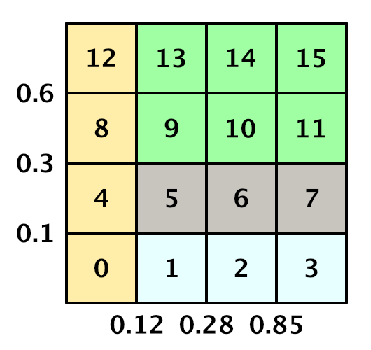
Matrix of biomes with indices of a one-dimensional array.
In order to determine the
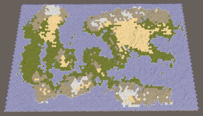
Relief based on the biome matrix.
We can not be limited to biomes given in the matrix. For example, in the matrix all dry biomes are defined as sandy deserts, but not all dry deserts are filled with sand. There are many stony deserts that look very different. So let's replace some of the desert cells with stones. We will do this simply on the basis of height: the sand is at low altitudes, and above usually there are bare rocks.
Assume that the sand turns into stone when the height of the cell is closer to the maximum height than to the water level. This is the height line of stony deserts, which we can calculate at the beginning
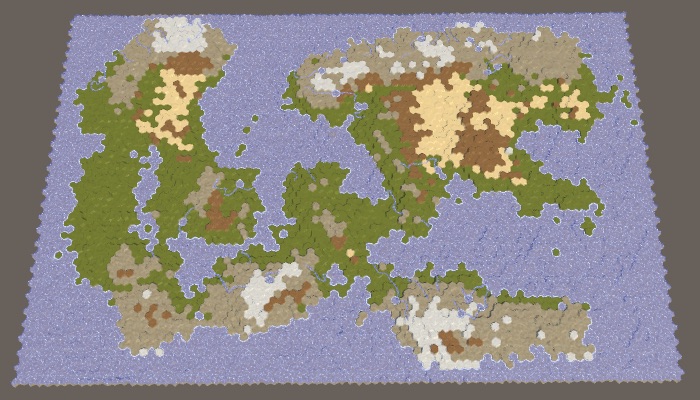
Sandy and stony deserts.
Another change based on height is to force cells at maximum height into snow peaks, regardless of their temperature, only if they are not too dry. This will increase the likelihood of snow peaks near the hot and humid equator.
Snow caps at maximum height.
Now let's make the biomes determine the level of the plant cells. To do this, add to the
In the coldest and driest biomes there will be no plants at all. In all other respects, the warmer and more humid the climate, the more plants. The second column of humidity gets only the first level of plants for the hottest row, so [0, 0, 0, 1]. The third column increases the levels by one, with the exception of snow, that is, [0, 1, 1, 2]. And the wettest column again increases them, that is, it turns out [0, 2, 2, 3]. Modify the array
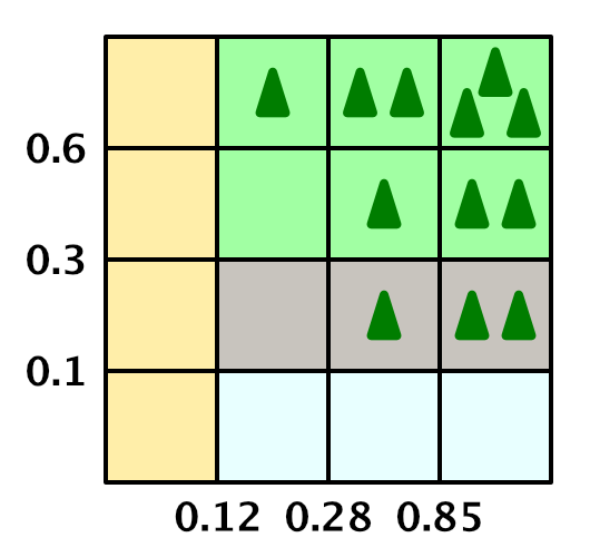
Biome matrix with plant levels.
Now we can set the level of plants for the cell.
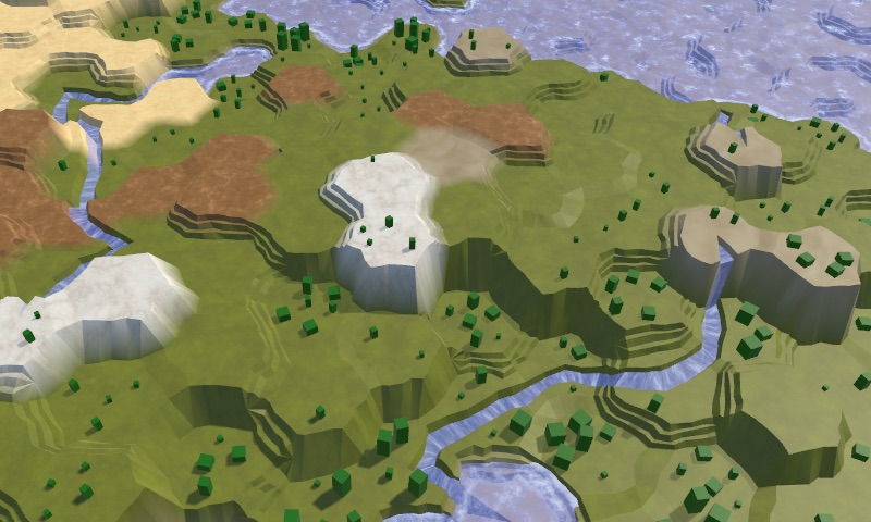
Biomes with plants.
We can change the level of plants for biomes. First, we need to make sure that they do not appear on the snow relief, which we could already adjust. Second, let's increase the level of plants along the rivers, if it is not yet at its maximum.

Altered plants.
Up to this point, we completely ignored the underwater cells. Let's add some variation to them and not use the texture of the earth for all of them. A simple solution based on height will be enough to create a more interesting picture. For example, let's use grass for cells with a height one step below the water level. Let's also use grass for cells above the water level, that is, for lakes created by rivers. Negative-height cells are deep-water areas, so we use stone for them. All other cells remain land.

Underwater variability.
Let's add some more details for the underwater cells along the coast. These are cells that have at least one neighbor above the water. If such a cell is shallow, then we will create a beach. And if it is near a cliff, then it will be the dominant visual detail, and we use stone.
To determine this, we will check the neighbors of the cells that are one step below the water level. Consider the number of connections by cliffs and slopes with adjacent cells, which are land.
Now we can use this information to classify cells. First, if more than half of the neighbors are land, then we are dealing with a lake or a bay. For such cells we use grass texture. Otherwise, if we have cliffs, then use a stone. Otherwise, if we have slopes, then we use sand to create a beach. The only remaining option is a shallow water area away from the coast, for which we still use grass.

Variability of the coast.
As a final touch, let's check that we do not have green underwater cells in the coldest temperature range. For such cells use land.
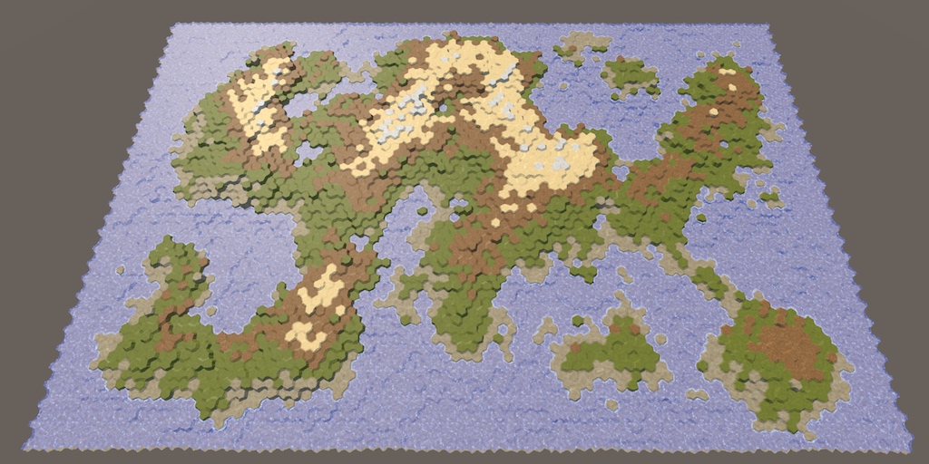
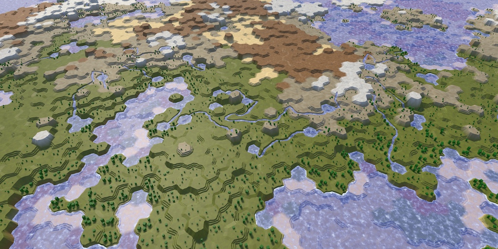
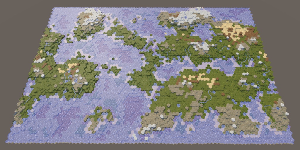
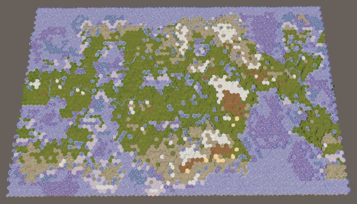
We were able to generate randomly looking, rather interesting and natural maps with many configuration options.
unitypackage
In this last part, we will add support for folding the map, connecting the eastern and western edges.
Tutorial created using Unity 2017.3.0p3.
Folding makes the world go round.
Our maps can be used to model areas of different sizes, but they are always limited to a rectangular shape. We can create a map of one island or a whole continent, but not the entire planet. Planets are spherical, they have no rigid boundaries that prevent movement on their surface. If you continue to move in one direction, then sooner or later you will return to the starting point.
We cannot wrap a grid of hexagons around a sphere, such an overlay is impossible. In the best approximations, the icosahedral topology is used, in which the twelve cells must be pentagons. However, without any distortions and exceptions, the mesh can be wrapped around a cylinder. To do this, simply connect the eastern and western edges of the map. With the exception of the wrapping logic, everything else remains the same.
The cylinder is a bad approximation of the sphere, because we cannot model the poles. But this did not prevent many game developers from using east-west folding to simulate maps of the planets. The polar regions are simply not part of the gaming zone.
There are two ways to implement cylindrical folding. The first is to actually make the map cylindrical, bending its surface and everything on it so that the eastern and western edges adjoin. Now you will play not on a flat surface, but on a real cylinder. The second approach is to save a flat map and use teleportation or duplication for folding. Most games use the second approach, so we take it.
The need for folding the map depends on its scale - local or planetary. We can use the support of both, making the folding optional. To do this, we will add a new switch to the Create New Map menu with minimization enabled by default.
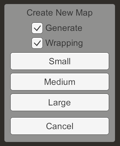
Menu new map with the option of folding.
Add in the
When a new map is requested, we transfer the value of the folding option.
Change it
code> HexGrid needs to know if we are doing the folding, so we will add a field to it and force it
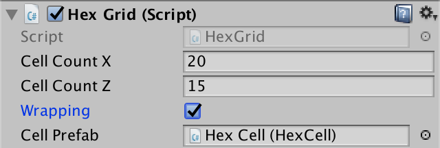
The grid folding switch is on by default.
Since folding is set for each card, it must be saved and loaded. This means that you need to change the format of the save file, so we will increase the version constant in
When saving, let
When loading we will read it only with the correct version of the file. If it is different, then this is an old map and it should not be rolled up. Save this information in a local variable and compare it with the current state of folding. If it is different, then we cannot reuse the existing topology of the map in the same way as it would when loading a map with other sizes.
To fold the map, serious changes in logic will be required, for example, when calculating distances. Therefore, they can touch code that does not have a direct reference to the grid. Instead of passing this information as arguments, let's add it to
We need to set the size of the collapse at each call
Since this data will not survive the recompilation in Play mode, we will also set it in
When working with collapsible maps, we often have to deal with positions along the X axis, measured in cell widths. Although it can be used for this
We can already use the diameter in three places. First, in
Secondly,
And also in the
unitypackage
When the map is not folded, it has clearly defined eastern and western edges, and therefore a clear center horizontally. But in the case of a folding card, everything is different. It has neither east, nor western region, nor center. Alternatively, we can assume that the center is where the camera is. This will be useful because we want the map to always be centered relative to our point of view. Then, wherever we are, we will not see either the east or west edges of the map.
In order for the map visualization to be centered relative to the camera, we need to change the placement of elements depending on the camera movement. If it moves to the west, then we need to take what is currently on the edge of the eastern part and move it to the edge of the western part. The same applies to the opposite direction.
Ideally, as soon as the camera shifts to the adjacent column of cells, we should immediately move the farthest column of cells to the other side. However, we do not need to be so accurate. Instead, we can transfer the entire map fragments. This allows us to move parts of the map without having to change the meshes.
Since we simultaneously move entire columns of fragments, let's group them together by creating a parent column object for each group. Add an array for these objects in
Now the fragment should become a child of the corresponding column, not the grid.
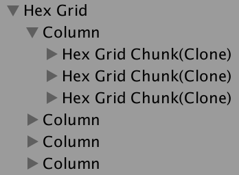
Fragments grouped into columns.
Since all fragments have now become child elements of columns,
Add a
It is enough for us to change the map visualization only when the index of the central column changes. So let's track it in the field. We use the default value −1 and when creating the map so that new maps are always centered.
Now that we know the index of the central column, we can determine the minimum and maximum indices by simply subtracting and adding half the number of columns. Since we use integer values, with an odd number of columns, this works perfectly. In the case of an even number of ideally centered columns can not be, therefore, one of the indices will be one step further than necessary. This creates an offset by one column in the direction of the farthest edge of the map, but for us this is not a problem.
Note that these indices may be negative or greater than the natural maximum index of a column. The minimum is zero only when the camera is near the natural center of the map. Our task is to move the columns so that they correspond to these relative indices. This can be done by changing the local X coordinate of each column in the loop.
For each column, we check if the index is less than the minimum index. If so, it is too far left from the center. He must teleport to the other side of the map. This can be done by making its X coordinate equal to the width of the map. Similarly, if the column index is greater than the maximum index, then it is too far to the right from the center, and must teleport in the other direction.
Let's change it
To make the map immediately centered, call the
Move left and right while centering on the camera.
Although we still limit camera movement, the map is now trying to center relative to the camera, if necessary, teleport the columns of the map fragments. With a small map and a distant camera, this is clearly visible, but on a large map, teleported fragments are outside the camera's view. Obviously, only the original eastern and western edges of the map are visible, because there is no triangulation between them.
In order to collapse the camera, remove the restriction of its X-coordinate
Collapsible camera moves along the map.
With the exception of the triangulation space, folding the camera in game mode should be imperceptible. However, when this occurs, a visual change occurs in half the relief and water. This happens because we use our position in the world to sample these textures. Sharp teleportation of the fragment changes the location of the textures.
We can solve this problem by arranging the textures to be arranged in tiles multiple to the size of the fragment. The fragment size is calculated from the constants in
This gives us a tiling scale of 0.00866025404. If we use an integer multiple of this value, then the fragment teleportation will not affect the texturing. In addition, the textures on the eastern and western edges of the map will be seamlessly connected after we correctly triangulate their connection. We used 0.02
as the UV scale in the Terrain shader . Instead, we can use the double tiling scale, which is 0.01732050808. The scale is slightly smaller than it was, and the scale of the texture has increased slightly, but visually it is imperceptible.
In the Roads shader for UV noise, we used a scale of 0.025. Instead, you can use the triple tiling scale. This gives us 0.02598076212, which is pretty close.
Finally, in Water.cginc we used 0.015 for foam and 0.025 for waves. Here again we can replace these values with a doubled and tripled scale of tiling.
unitypackage
At this stage, the only visual evidence of map folding is a small space between the most eastern and western columns. This space occurs because we do not yet triangulate the connections of edges and angles between cells on opposite sides of the map without folding.

Space on the edge.
To triangulate the east-west connection, we need to make cells on opposite sides of each other’s neighbors. So far we are not doing this, because the
Having established the connection of the E – W neighbors, we obtain a partial triangulation of the gap. The connection of edges is imperfect, because the distortions are hidden incorrectly. We will deal with this later.

E – W connections.
We also need to collapse the NE – SW links. This can be done by connecting the first cell of each even row with the last cells of the previous row. This will be just the previous cell.
NE – SW connections.
Finally, the SE – NW connections are established at the end of each odd line below the first. These cells should connect to the first cell of the previous row.
SE – NW connections.
In order to perfectly hide the gap, we need to ensure that on the eastern and western edges of the map there is a perfect match between the noise used to distort the vertex positions. We can use the same trick used for shaders, but the noise scale is 0.003 for distortion. To provide tiling, you need to significantly increase the scale, which will lead to a more chaotic distortion of the vertices.
An alternative solution is not to damp noise, but to make a smooth attenuation of noise along the edges of the card. If you perform a smooth attenuation along the width of a single cell, then the distortion will create a smooth transition without breaks. The noise in this area will be slightly smoothed, and from a long distance the change will seem abrupt, but this is not so obvious when using a slight distortion of the vertices.
If we do not fold the card, then we can do in a
When folding, we need to perform mixing with the second sample. We will perform the transition in the eastern part of the map, so the second sample must be moved to the west side.
Attenuation is performed using simple linear interpolation from the west to the east, over the width of one cell.

Mixing noise, a non-ideal solution.
As a result, we get a not quite exact match, because part of the cells on the east side has negative X coordinates. In order not to approach this area, let's move the transition area to the west by half the cell width.

Correct attenuation.
Now that the triangulation seems correct, let's make sure that we can edit everything on the map and on the folding seam. As it turns out, in teleported fragments, the coordinates are erroneous and large brushes are cut off with a seam.
Brush cut.
To fix this, we need to report
Sometimes when I edit the bottom or top of the map, I get errors.
This happens when, due to the distortion of the vertices, the cursor appears in a row of cells outside the map. This is a bug that occurs because we do not match the coordinates in
Triangulation works well for relief, but along the east-west seam there are no edges of the coast. In fact, they are, they just do not fold. They are flipped and stretched to the other side of the card.

Missing water edge.
This happens because we use the position of a neighbor when triangulating the water of the coast. To fix this, we need to determine that we are dealing on the other side of the map. To simplify the task, we will add the
Assign this index to
Now we can
Ribs of the coast, but no corners.
So we took care of the edges of the coast, but so far we have not dealt with the corners. We need to do the same with the next neighbor.

Properly folded coast.
The option of connecting the east and west sides affects the generation of maps. When the map is minimized, the generation algorithm must also be minimized. This will create another map, but when using a non-zero Map Border X, folding is not obvious.

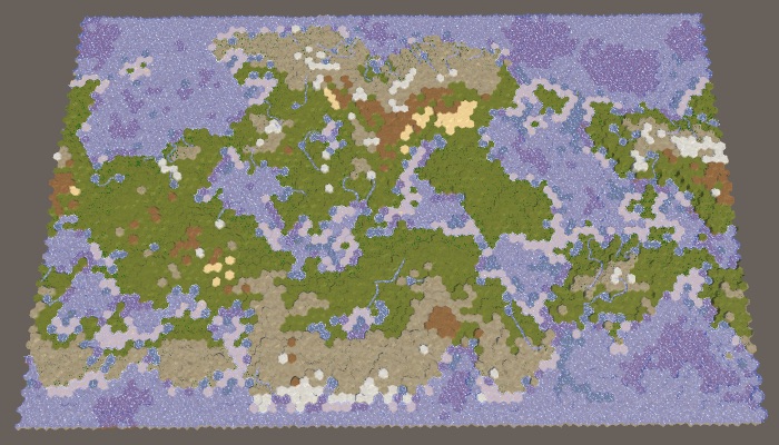
Large map 1208905299 with default settings. With and without folding.
When minimized it does not make sense to use the Map Border the X . But we can not just get rid of him, because in this case the regions will merge. When minimized, we can simply use RegionBorder instead .
Change
At the same time, the regions remain separate, but this is necessary only if there are different regions on the east and west sides of the map. There are two cases when this is not respected. The first is when we have only one region. The second is when there are two regions separating the map horizontally. In these cases, we can assign a

One region of folding.
At first glance, it seems that everything is working correctly, but there is actually a gap along the seam. This becomes more noticeable if you assign a zero value to Erosion Percentage .
When the erosion is turned off, the seam on the relief becomes noticeable.
A rupture occurs because the seam prevents the growth of relief fragments. To determine what is added first, the distance from the cell to the center of the fragment is used, and the cells on the other side of the map can be very far away, so they almost never turn on. Of course, this is wrong. We need to make sure that
We calculate the distance between
Determining whether folding creates a smaller distance for arbitrary cells is not a simple task, so let's just calculate X + Y for cases when we fold another coordinate to the west side. If the value is less than the original X + Y, then use it.
If this does not lead to a shorter distance, then there is a possibility of folding shorter in another direction, so check it out.
Now we always get as a result the shortest distance on the collapsible map. Relief fragments are no longer blocked by a seam, which allows the land masses to curl.

Properly rolled relief without erosion and with erosion.
unitypackage
Having considered the card generation and triangulation, let's now move on to checking units, research and visibility.
The first obstacle that we encounter when moving a detachment around the world is the edge of the map that cannot be explored.

Card seam cannot be explored.
The cells along the edge of the map are made unexplored to hide the abrupt completion of the map. But when the map is minimized, only the northern and southern cells should be marked, but not the eastern and western cells. Change
Now let's check if visibility is working right along the seam. It works for the relief, but not for the objects of the relief. It seems that the collapsed objects get the visibility of the last cell that was not collapsed.

Incorrect visibility of objects.
This happens because the clamping mode
Another problem is that the units are not collapsing yet. After moving the column in which they are located, the detachments remain in the same place.
The detachment is not transferred and is on the wrong side.
This problem can be solved by making the units the children of the columns, as we did with the fragments. First, we will no longer make them the immediate children of the grid in
As the units move, they may end up in a different column, that is, their parent will need to change. To make this possible, we add it to the
We will call this method when the property is set
This solves the problem with the creation of units. But we also need to make them move to the right column when moving. To do this, you need to track the
During each iteration of the move we will check if the index of the next column is different, and if so, change the parent of the squad.
This will allow units to move in the same way as fragments. However, while moving through the seam of the map, the detachments do not yet collapse. Instead, they suddenly begin to move in the wrong direction. This happens regardless of the location of the seam, but most noticeably when they jump across the entire map.
Racing through the map.
Here we can use the same approach that was used for the coast, only this time we will fold the curve along which the detachment moves. If the next column is turned east, we will teleport the curve to the east too, similarly for another direction. You need to change the control points of the curve
Movement with folding.
The last thing to do is to change the initial turn of the squad when it looks at the first cell to which it moves. If this cell is on the other side of the east-west seam, the unit will look in the wrong direction.
When folding a map, there are two ways to look at a point that is not exactly located in the north or south. You can look either to the east or to the west. It will be logical to look in the direction corresponding to the closest distance to the point, because it is also the direction of motion, so let's use it in
When folding, we will check the relative distance along the X axis. If it is smaller than the negative half of the width of the map, then we must look to the west, which can be done by turning the point to the west. Otherwise, if the distance is more than half the width of the map, then we must roll up to the east.
So, we have a full-featured map with folding. And with this we complete the series of tutorials on hexagon maps. As mentioned in the previous sections, other topics may be considered, but they do not relate specifically to hexagon maps. Perhaps I will consider them in future series of tutorials.
unitypackage
Parts 4-7: bumps, rivers and roads
Parts 8-11: water, landforms and walls
')
Parts 12-15: saving and loading, textures, distances
Parts 16-19: Pathfinding, Player Squads, Animations
Parts 20-23: fog of war, map exploration, procedural generation
Parts 24-27: water cycle, erosion, biomes, cylindrical map
Part 24: Regions and Erosion
- Add a border out of the water around the map.
- We divide the map into several regions.
- We use erosion to cut the cliffs.
- Move the land to smooth relief.
In the previous section, we laid the foundation for procedural map generation. This time we will limit the places of possible land appearance and act on it with erosion.
This tutorial was created in Unity 2017.1.0.
We divide and smooth the land.
Map boundary
As we pick up land at random, it may happen that the land touches the edge of the map. This may not be desirable. A water-bound card contains a natural barrier that prevents players from approaching the edge. Therefore, it would be nice if we banned land from rising above the water level near the edge of the map.
Border size
How close should the land be to the edge of the map? There is no right answer to this question, therefore we will make this parameter customizable. We will add two sliders to the
HexMapGenerator component, one for the borders along the edges along the X axis, the other for the borders along the Z axis. So we can use a wider border in one of the dimensions, or even create a border in only one dimension. Let's use the interval from 0 to 10 with a default value of 5. [Range(0, 10)] public int mapBorderX = 5; [Range(0, 10)] public int mapBorderZ = 5; Card sliders.
We limit the land centers
Without boundaries, all cells are valid. When the boundaries are present, the minimum allowable offset coordinates increase, and the maximum allowable coordinates decrease. Since to generate plots we need to know the allowable interval, let's track it with the help of four integer fields.
int xMin, xMax, zMin, zMax; Initialize constraints in
GenerateMap before creating sushi. We use these values as parameters for Random.Range calls, so the maxima are in fact exceptional. Without a border, they are equal to the number of measurement cells, therefore, not minus 1. public void GenerateMap (int x, int z) { … for (int i = 0; i < cellCount; i++) { grid.GetCell(i).WaterLevel = waterLevel; } xMin = mapBorderX; xMax = x - mapBorderX; zMin = mapBorderZ; zMax = z - mapBorderZ; CreateLand(); … } We will not strictly prohibit the appearance of land beyond the edge of the border, because this would create sharply cut edges. Instead, we will restrict only the cells used to start generating plots. That is, the approximate centers of the sections will be limited, but parts of the sections will be able to go beyond the border area. This can be done by changing
GetRandomCell so that it selects a cell in the interval of allowable offsets. HexCell GetRandomCell () { // return grid.GetCell(Random.Range(0, cellCount)); return grid.GetCell(Random.Range(xMin, xMax), Random.Range(zMin, zMax)); } The borders of the map are 0 × 0, 5 × 5, 10 × 10 and 0 × 10.
When all parameters of the map are set to default values, the border of size 5 will reliably protect the edge of the map from touching the land. However, this is not guaranteed. Drying can sometimes come close to the edge, and sometimes touch it in several places.
The likelihood that land will cross the entire border depends on the size of the border and the maximum size of the site. Without hesitation, areas remain hexagons. Full hexagon with radius contains cells If there are hexagons with a radius equal to the size of the border, then they will be able to cross it. A full hexagon with a radius of 5 contains 91 cells. Since the default maximum is 100 cells per plot, this means that the land will be able to pave a bridge across 5 cells, especially if there are fluctuations. To prevent this from happening, either reduce the maximum size of the area or increase the size of the border.
How is the formula for the number of cells in the hexagonal region derived?
With a radius of 0, we are dealing with a single cell. From here it took 1. With a radius of 1 around the center there are six additional cells, i.e. . These six cells can be considered the ends of six triangles tangent to the center. With a radius of 2, a second row is added to these triangles, that is, two more cells are obtained on the triangle, and . With a radius of 3, a third row is added, that is, three more cells per triangle, and the total . And so on. That is, in general terms, the formula looks like .
To see this more clearly, we can set the border size to 200. Since the full hexagon with a radius of 8 contains 217 cells, the land will most likely touch the edge of the map. At least, if you use the default border size value (5). Increasing the boundary to 10 will greatly decrease the probability.
The land area has a constant size of 200, the boundaries of the map are 5 and 10.
Pangea
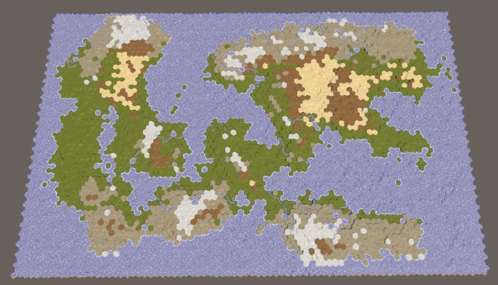
Note that by increasing the border of the map and maintaining the same percentage of land, we force the land to form a smaller area. As a result, a large default map is likely to create a single large mass of land — the supercontinent Pangea — possibly with several small islands. With an increase in the size of the border, the probability of this increases, and at certain values, we are almost guaranteed to get the supercontinent. However, when the percentage of land is too large, most of the available areas are filled and as a result we get an almost rectangular mass of land. To avoid this, you need to reduce the percentage of land.
40% sushi with border cards 10.
Where did the name Pangea come from?
That was the name of the last known supercontinent that existed on Earth many years ago. The name is composed of the Greek words pan and Gaia, meaning something like “all nature” or “all land”.
Defending against impossible cards
We generate the right amount of land, simply continuing to raise the land until we reach the desired land mass. It works, because sooner or later we will raise each cell on the water level. However, when using the border of the map, we cannot reach every cell. When a very high percentage of land is required, it will lead to endless "attempts and failures" of the generator to raise more land, and it will get stuck in an endless cycle. The application will freeze, but this should not happen.
We cannot reliably find impossible configurations in advance, but we can protect ourselves from infinite loops. We will simply track the number of cycles executed in
CreateLand . If there are too many iterations, then we are most likely stuck and should stop.For a large map, a value of a thousand iterations seems acceptable, and ten thousand iterations already seem absurd. So let's use this value as the end point.
void CreateLand () { int landBudget = Mathf.RoundToInt(cellCount * landPercentage * 0.01f); // while (landBudget > 0) { for (int guard = 0; landBudget > 0 && guard < 10000; guard++) { int chunkSize = Random.Range(chunkSizeMin, chunkSizeMax - 1); … } } If we get a spoiled map, then performing 10,000 iterations will not take much time, because many cells will quickly reach their maximum height, which will prevent new areas from growing.
Even after interrupting the cycle, we still get the right map. It just does not have the right amount of sushi and it will not look very interesting. Let's display a notification to the console, informing us of the remaining amount of land we could not spend.
void CreateLand () { … if (landBudget > 0) { Debug.LogWarning("Failed to use up " + landBudget + " land budget."); } } 95% of the land with a border of 10 cards could not spend the entire amount.
Why does a failed card still have variability?
The coastline is variable, because when the heights inside the creation area become too high, new areas prevent them from growing outwards. The same principle does not allow the sites to grow into small areas of land, not yet reached the maximum height and just disappeared. In addition, the variability increases with lowering plots.
unitypackage
Splitting the card into parts
Now that we have a map boundary, we essentially divided the map into two separate regions: the region of the border and the region of creation of the plots. Since only the region of creation is important for us, we can consider such a situation as a situation with one region. The region simply does not cover the entire map. But if this is not possible, then nothing prevents us from dividing the map into several unconnected regions of land creation. This will allow land masses to form independently of each other, denoting different continents.
Map Region
Let's start by describing one region of the map as a struct. This will make it easier for us to work with several regions. For this we create a
MapRegion structure, which simply contains the fields of the region’s borders. Since we will not use this structure outside the HexMapGenerator , we can define it within this class as a private internal structure. Then four integer fields can be replaced with one MapRegion field. // int xMin, xMax, zMin, zMax; struct MapRegion { public int xMin, xMax, zMin, zMax; } MapRegion region; For everything to work, we need to add the
region. prefix to the fields of minimum-maximum in GenerateMap region. . region.xMin = mapBorderX; region.xMax = x - mapBorderX; region.zMin = mapBorderZ; region.zMax = z - mapBorderZ; And also in
GetRandomCell . HexCell GetRandomCell () { return grid.GetCell( Random.Range(region.xMin, region.xMax), Random.Range(region.zMin, region.zMax) ); } Several regions
To support multiple regions, replace one
MapRegion field MapRegion list of regions. // MapRegion region; List<MapRegion> regions; At this stage, it would be nice to add a separate method for creating regions. It must create the desired list or clear it if it already exists. After that, it will identify one region, as we did before, and add it to the list.
void CreateRegions () { if (regions == null) { regions = new List<MapRegion>(); } else { regions.Clear(); } MapRegion region; region.xMin = mapBorderX; region.xMax = grid.cellCountX - mapBorderX; region.zMin = mapBorderZ; region.zMax = grid.cellCountZ - mapBorderZ; regions.Add(region); } Let's call this method in
GenerateMap , but we will not create a region directly. // region.xMin = mapBorderX; // region.xMax = x - mapBorderX; // region.zMin = mapBorderZ; // region.zMax = z - mapBorderZ; CreateRegions(); CreateLand(); In order for
GetRandomCell to work with an arbitrary region, we give it the MapRegion parameter. HexCell GetRandomCell (MapRegion region) { return grid.GetCell( Random.Range(region.xMin, region.xMax), Random.Range(region.zMin, region.zMax) ); } Now the
RaiseTerraion and SinkTerrain must pass the corresponding region to GetRandomCell . To do this, each of them also needs a region parameter. int RaiseTerrain (int chunkSize, int budget, MapRegion region) { searchFrontierPhase += 1; HexCell firstCell = GetRandomCell(region); … } int SinkTerrain (int chunkSize, int budget, MapRegion region) { searchFrontierPhase += 1; HexCell firstCell = GetRandomCell(region); … } The
CreateLand method should determine if each region should be raised or lowered. In order to balance land between regions, we will simply bypass the list of regions in a cycle over and over again. void CreateLand () { int landBudget = Mathf.RoundToInt(cellCount * landPercentage * 0.01f); for (int guard = 0; landBudget > 0 && guard < 10000; guard++) { for (int i = 0; i < regions.Count; i++) { MapRegion region = regions[i]; int chunkSize = Random.Range(chunkSizeMin, chunkSizeMax - 1); if (Random.value < sinkProbability) { landBudget = SinkTerrain(chunkSize, landBudget, region); } else { landBudget = RaiseTerrain(chunkSize, landBudget, region); } } } if (landBudget > 0) { Debug.LogWarning("Failed to use up " + landBudget + " land budget."); } } However, we still need to do so that the lowering of the plots is distributed evenly. This can be done while deciding for all regions whether to lower them.
for (int guard = 0; landBudget > 0 && guard < 10000; guard++) { bool sink = Random.value < sinkProbability; for (int i = 0; i < regions.Count; i++) { MapRegion region = regions[i]; int chunkSize = Random.Range(chunkSizeMin, chunkSizeMax - 1); // if (Random.value < sinkProbability) { if (sink) { landBudget = SinkTerrain(chunkSize, landBudget, region); } else { landBudget = RaiseTerrain(chunkSize, landBudget, region); } } } Finally, to use exactly the entire amount of land, we need to stop the process as soon as the amount reaches zero. This can occur at any stage of the region's cycle. Therefore, we move the check to zero amount in the inner loop. In fact, we can perform this check only after raising land, because when lowering the amount is never spent. If we are done, we can immediately exit the
CreateLand method. // for (int guard = 0; landBudget > 0 && guard < 10000; guard++) { for (int guard = 0; guard < 10000; guard++) { bool sink = Random.value < sinkProbability; for (int i = 0; i < regions.Count; i++) { MapRegion region = regions[i]; int chunkSize = Random.Range(chunkSizeMin, chunkSizeMax - 1); if (sink) { landBudget = SinkTerrain(chunkSize, landBudget, region); } else { landBudget = RaiseTerrain(chunkSize, landBudget, region); if (landBudget == 0) { return; } } } } Two regions
Although we now have the support of several regions, we still ask only one. Let's change
CreateRegions so that it divides the map in half vertically. To do this, halve the value of xMax added region. Then use the same value for xMin and again use the original value for xMax , using it as the second region. MapRegion region; region.xMin = mapBorderX; region.xMax = grid.cellCountX / 2; region.zMin = mapBorderZ; region.zMax = grid.cellCountZ - mapBorderZ; regions.Add(region); region.xMin = grid.cellCountX / 2; region.xMax = grid.cellCountX - mapBorderX; regions.Add(region); Generating maps at this stage will not make any difference. Although we have defined two regions, they occupy the same region as one old region. To separate them to the side, you need to leave between them an empty space. This can be done by adding a region border slider, using the same interval and default value as for the map borders.
[Range(0, 10)] public int regionBorder = 5; Slider border region.
Since the land can be formed on either side of the space between the regions, the probability of creating bridges from land at the edges of the map will increase. To prevent this, we use the region's border to set the land-free zone between the dividing line and the area in which the plots can begin. This means that the distance between neighboring regions is two more than the size of the border of the region.
To apply this region boundary, subtract it from the
xMax first region and add to xMin second region. MapRegion region; region.xMin = mapBorderX; region.xMax = grid.cellCountX / 2 - regionBorder; region.zMin = mapBorderZ; region.zMax = grid.cellCountZ - mapBorderZ; regions.Add(region); region.xMin = grid.cellCountX / 2 + regionBorder; region.xMax = grid.cellCountX - mapBorderX; regions.Add(region); The map is divided vertically into two regions.
With the default parameters, two noticeably separated regions will be created, however, as in the case of one region and a large map boundary, we are not guaranteed to get exactly two land masses. Most often it will be two large continents, possibly with several islands. But sometimes two or more large islands can be created in a region. And sometimes two continents can be connected by an isthmus.
Of course, we can also split the map horizontally by changing the approaches for measuring X and Z. Let's randomly choose one of two possible orientations.
MapRegion region; if (Random.value < 0.5f) { region.xMin = mapBorderX; region.xMax = grid.cellCountX / 2 - regionBorder; region.zMin = mapBorderZ; region.zMax = grid.cellCountZ - mapBorderZ; regions.Add(region); region.xMin = grid.cellCountX / 2 + regionBorder; region.xMax = grid.cellCountX - mapBorderX; regions.Add(region); } else { region.xMin = mapBorderX; region.xMax = grid.cellCountX - mapBorderX; region.zMin = mapBorderZ; region.zMax = grid.cellCountZ / 2 - regionBorder; regions.Add(region); region.zMin = grid.cellCountZ / 2 + regionBorder; region.zMax = grid.cellCountZ - mapBorderZ; regions.Add(region); } Map horizontally divided into two regions.
Since we use a wide map, with horizontal separation, wider and thinner regions will be created. As a result, these regions are more likely to form several divided land masses.
Four regions
Let's make the number of regions customizable, create support from 1 to 4 regions.
[Range(1, 4)] public int regionCount = 1; Slider for the number of regions.
We can use the
switch to select the execution of the corresponding region code. We start by repeating the code for one region, which will be used by default, and leave the code for the two regions for case 2. MapRegion region; switch (regionCount) { default: region.xMin = mapBorderX; region.xMax = grid.cellCountX - mapBorderX; region.zMin = mapBorderZ; region.zMax = grid.cellCountZ - mapBorderZ; regions.Add(region); break; case 2: if (Random.value < 0.5f) { region.xMin = mapBorderX; region.xMax = grid.cellCountX / 2 - regionBorder; region.zMin = mapBorderZ; region.zMax = grid.cellCountZ - mapBorderZ; regions.Add(region); region.xMin = grid.cellCountX / 2 + regionBorder; region.xMax = grid.cellCountX - mapBorderX; regions.Add(region); } else { region.xMin = mapBorderX; region.xMax = grid.cellCountX - mapBorderX; region.zMin = mapBorderZ; region.zMax = grid.cellCountZ / 2 - regionBorder; regions.Add(region); region.zMin = grid.cellCountZ / 2 + regionBorder; region.zMax = grid.cellCountZ - mapBorderZ; regions.Add(region); } break; } What kind of switch statement?
This is an alternative to writing a sequence of if-else-if-else statements. switch is applied to a variable, and labels are used to indicate which code to execute. There is also a label
In order for a
default , which is used as the last block else . Each option must be completed with either a break statement or a return .In order for a
switch block to remain readable, it is usually best to make all cases short, ideally with a single statement or method call. I will not do this for an example of a region code, but if you want to create more interesting regions, I recommend that you use separate methods. For example: switch (regionCount) { default: CreateOneRegion(); break; case 2: CreateTwoRegions(); break; case 3: CreateThreeRegions(); break; case 4: CreateFourRegions(); break; } Three regions are like two, only thirds are used instead of half. In this case, the horizontal separation will create too narrow regions, so we created support only for the vertical separation. Notice that as a result we have double the space of the region’s border, therefore there is less space for creating new sites than in the case of two regions.
switch (regionCount) { default: … break; case 2: … break; case 3: region.xMin = mapBorderX; region.xMax = grid.cellCountX / 3 - regionBorder; region.zMin = mapBorderZ; region.zMax = grid.cellCountZ - mapBorderZ; regions.Add(region); region.xMin = grid.cellCountX / 3 + regionBorder; region.xMax = grid.cellCountX * 2 / 3 - regionBorder; regions.Add(region); region.xMin = grid.cellCountX * 2 / 3 + regionBorder; region.xMax = grid.cellCountX - mapBorderX; regions.Add(region); break; } Three regions.
Four regions can be created by combining horizontal and vertical divisions and adding one region to each corner of the map.
switch (regionCount) { … case 4: region.xMin = mapBorderX; region.xMax = grid.cellCountX / 2 - regionBorder; region.zMin = mapBorderZ; region.zMax = grid.cellCountZ / 2 - regionBorder; regions.Add(region); region.xMin = grid.cellCountX / 2 + regionBorder; region.xMax = grid.cellCountX - mapBorderX; regions.Add(region); region.zMin = grid.cellCountZ / 2 + regionBorder; region.zMax = grid.cellCountZ - mapBorderZ; regions.Add(region); region.xMin = mapBorderX; region.xMax = grid.cellCountX / 2 - regionBorder; regions.Add(region); break; } } Four regions.
The approach used here is the simplest way to split a card. It generates approximately the same land mass in terms of mass, and their variability is controlled by other map generation parameters. However, it will always be pretty obvious that the map was divided along straight lines. The more control we need, the less organic the result will look. Therefore, it is normal if you need approximately equal regions for gameplay. But if you need the most variable and unlimited land, you will have to make it with the help of one region.
In addition, there are other ways to split a map. We can not be limited to straight lines. We are not even obliged to use regions of the same size, as well as cover the entire map with them. We can leave holes. You can also allow the intersection of regions or change the distribution of land between regions. You can even set your own generator parameters for each region (although this is more difficult), for example, so that both a large continent and an archipelago are on the map.
unitypackage
Erosion
So far, all the cards we generated looked pretty rough and broken.The real relief may look like this, but over time it becomes smoother and smoothed, its sharp parts become dull due to erosion. To improve the maps, we can apply this process of erosion. We will do this after creating coarse sushi, in a separate method.
public void GenerateMap (int x, int z) { … CreateRegions(); CreateLand(); ErodeLand(); SetTerrainType(); … } … void ErodeLand () {} Erosion rate
The more time passes, the more erosion appears. Therefore, we want erosion to be not permanent, but customizable. At a minimum, erosion is zero, which corresponds to the maps created earlier. At maximum, erosion is comprehensive, that is, the further application of erosion forces will no longer change the relief. That is, the erosion parameter should be a percentage from 0 to 100, and by default we take 50.
[Range(0, 100)] public int erosionPercentage = 50; Slider erosion.
Search for destructible cells
Erosion makes the relief smoother. In our case, the only sharp parts are the cliffs. Therefore, the purpose of the erosion process will be they. If a precipice exists, erosion should reduce it, until it eventually turns into a slope. We will not smooth the slopes, because it will lead to dull relief. To do this, we need to determine which cells are on the tops of the cliffs, and reduce their height. These will be erosion prone cells.
Let's create a method that determines whether a cell can be subject to erosion. He determines this by checking the neighbors of the cell until he finds a large enough height difference. Since the cliffs need a difference of at least one or two levels of height, the cell is prone to erosion if one or several of its neighbors are at least two steps below it. If there is no such neighbor, the cell cannot be eroded.
bool IsErodible (HexCell cell) { int erodibleElevation = cell.Elevation - 2; for (HexDirection d = HexDirection.NE; d <= HexDirection.NW; d++) { HexCell neighbor = cell.GetNeighbor(d); if (neighbor && neighbor.Elevation <= erodibleElevation) { return true; } } return false; } We can use this method to
ErodeLandcycle through all cells and write all eroded cells to a temporary list. void ErodeLand () { List<HexCell> erodibleCells = ListPool<HexCell>.Get(); for (int i = 0; i < cellCount; i++) { HexCell cell = grid.GetCell(i); if (IsErodible(cell)) { erodibleCells.Add(cell); } } ListPool<HexCell>.Add(erodibleCells); } As soon as we know the total number of erosion-prone cells, we can use the percentage of erosion to determine the number of remaining erosion-prone cells. For example, if the percentage is 50, then we must subject the cells to erosion, until half of the original amount remains. If the percentage is 100, then we will not stop until we destroy all erosion prone cells.
void ErodeLand () { List<HexCell> erodibleCells = ListPool<HexCell>.Get(); for (int i = 0; i < cellCount; i++) { … } int targetErodibleCount = (int)(erodibleCells.Count * (100 - erosionPercentage) * 0.01f); ListPool<HexCell>.Add(erodibleCells); } Shouldn't we consider only eroded land cells?
. , , .
Cell reduction
Let's start with a naive approach and assume that simply lowering the height of a cell destroyed by erosion will make it no longer prone to erosion. If this were true, then we could just take random cells from the list, lower their height, and then remove them from the list. We would repeat this operation until we reach the required number of eroded cells.
int targetErodibleCount = (int)(erodibleCells.Count * (100 - erosionPercentage) * 0.01f); while (erodibleCells.Count > targetErodibleCount) { int index = Random.Range(0, erodibleCells.Count); HexCell cell = erodibleCells[index]; cell.Elevation -= 1; erodibleCells.Remove(cell); } ListPool<HexCell>.Add(erodibleCells); To prevent the search required
erodibleCells.Remove, we will rewrite the current cell last in the list, and then delete the last element. We still do not care about their order. // erodibleCells.Remove(cell); erodibleCells[index] = erodibleCells[erodibleCells.Count - 1]; erodibleCells.RemoveAt(erodibleCells.Count - 1); A naive decrease in 0% and 100% erosion-prone cells, seed cards 1957632474.
Erosion tracking
Our naive approach allows us to apply erosion, but not to the necessary extent. This happens because the cell can still remain subject to erosion after one drop in height. Therefore, we will remove a cell from the list only when it is no longer subject to erosion.
if (!IsErodible(cell)) { erodibleCells[index] = erodibleCells[erodibleCells.Count - 1]; erodibleCells.RemoveAt(erodibleCells.Count - 1); } 100% erosion while maintaining the erosion-prone cells in the list.
So we get much more erosion, but using 100%, we still do not get rid of all the cliffs. The reason is that after reducing the height of the cell, one of its neighbors may become eroded. Therefore, as a result, we may have more erosion prone cells than was originally.
After lowering the cell, we need to check all its neighbors. If now they are subject to erosion, but they are not yet in the list, then you need to add them there.
if (!IsErodible(cell)) { erodibleCells[index] = erodibleCells[erodibleCells.Count - 1]; erodibleCells.RemoveAt(erodibleCells.Count - 1); } for (HexDirection d = HexDirection.NE; d <= HexDirection.NW; d++) { HexCell neighbor = cell.GetNeighbor(d); if ( neighbor && IsErodible(neighbor) && !erodibleCells.Contains(neighbor) ) { erodibleCells.Add(neighbor); } } All erosion prone cells are omitted.
We save a lot of sushi
Now the process of erosion can continue until all the cliffs disappear. This significantly affects the land. Most of the land mass disappeared and we got a much smaller percentage of the land needed. It happened because we remove land from the map.
True erosion does not destroy matter. She takes her from one place and places her somewhere else. We can do the same. By dropping one cell, we have to pick up one of its neighbors. In fact, one level of height is transferred to a lower cell. This saves the total amount of map heights, while simply smoothing it out.
To realize this, we need to decide where to move the products of erosion. This will be our target point of erosion. Let's create a method to determine the target point of the cell that will be eroded. Since this cell contains a break, it will be logical to select a cell under this break as a target. But a cell prone to erosion may have several cliffs, so check all the neighbors and put all candidates on a temporary list, and then we will choose one of them randomly.
HexCell GetErosionTarget (HexCell cell) { List<HexCell> candidates = ListPool<HexCell>.Get(); int erodibleElevation = cell.Elevation - 2; for (HexDirection d = HexDirection.NE; d <= HexDirection.NW; d++) { HexCell neighbor = cell.GetNeighbor(d); if (neighbor && neighbor.Elevation <= erodibleElevation) { candidates.Add(neighbor); } } HexCell target = candidates[Random.Range(0, candidates.Count)]; ListPool<HexCell>.Add(candidates); return target; } In
ErodeLandwe determine the target cell immediately after the selection of the cell to be eroded. Then we decrease and increase the heights of the cells immediately one after another. At the same time, the target cell itself may become subject to erosion, but this situation is resolved when we check the neighbors of the cell just eroded. HexCell cell = erodibleCells[index]; HexCell targetCell = GetErosionTarget(cell); cell.Elevation -= 1; targetCell.Elevation += 1; if (!IsErodible(cell)) { erodibleCells[index] = erodibleCells[erodibleCells.Count - 1]; erodibleCells.RemoveAt(erodibleCells.Count - 1); } Since we raised the target cell, part of the neighbors of this cell may cease to be subject to erosion. It is necessary to bypass them and check whether they are subject to erosion. If not, but they are in the list, then you need to remove them from it.
for (HexDirection d = HexDirection.NE; d <= HexDirection.NW; d++) { HexCell neighbor = cell.GetNeighbor(d); … } for (HexDirection d = HexDirection.NE; d <= HexDirection.NW; d++) { HexCell neighbor = targetCell.GetNeighbor(d); if ( neighbor && !IsErodible(neighbor) && erodibleCells.Contains(neighbor) ) { erodibleCells.Remove(neighbor); } } 100% erosion preserving the mass of land.
Now, erosion can smooth out the relief much better, lowering some areas and raising others. As a result, the mass of land can both increase and narrow. This may change the percentage of land on a few percent in one direction or another, but serious deviations rarely occur. That is, the more erosion we apply, the less control we will have over the resulting percentage of land.
Accelerated erosion
Although we do not need to worry about the effectiveness of the erosion algorithm, it is possible to make simple improvements to it. First, note that we are explicitly checking whether the cell we have eroded can be eroded. If not, then essentially we remove it from the list. Therefore, you can skip checking this cell when traversing the neighbors of the target cell.
for (HexDirection d = HexDirection.NE; d <= HexDirection.NW; d++) { HexCell neighbor = targetCell.GetNeighbor(d); if ( neighbor && neighbor != cell && !IsErodible(neighbor) && erodibleCells.Contains(neighbor) ) { erodibleCells.Remove(neighbor); } } Secondly, we only needed to check the neighbors of the target cell when there was a break between them, but now it is not necessary. This happens only when the neighbor is now one step higher than the target cell. If this is so, then the neighbor is guaranteed to be on the list, so we don’t need to check it, that is, we can skip an unnecessary search.
HexCell neighbor = targetCell.GetNeighbor(d); if ( neighbor && neighbor != cell && neighbor.Elevation == targetCell.Elevation + 1 && !IsErodible(neighbor) // && erodibleCells.Contains(neighbor) ) { erodibleCells.Remove(neighbor); } Thirdly, we can use a similar trick when checking the neighbors of an erosion-prone cell. If there is a cliff between them now, then the neighbor is subject to erosion. To find out, we do not need to call
IsErodible. HexCell neighbor = cell.GetNeighbor(d); if ( neighbor && neighbor.Elevation == cell.Elevation + 2 && // IsErodible(neighbor) && !erodibleCells.Contains(neighbor) ) { erodibleCells.Add(neighbor); } However, we still need to check whether the target cell is prone to erosion, but the cycle shown above no longer does this. Therefore, we do this explicitly for the target cell.
if (!IsErodible(cell)) { erodibleCells[index] = erodibleCells[erodibleCells.Count - 1]; erodibleCells.RemoveAt(erodibleCells.Count - 1); } for (HexDirection d = HexDirection.NE; d <= HexDirection.NW; d++) { … } if (IsErodible(targetCell) && !erodibleCells.Contains(targetCell)) { erodibleCells.Add(targetCell); } for (HexDirection d = HexDirection.NE; d <= HexDirection.NW; d++) { … } Now we can apply erosion rather quickly and to the desired percentage relative to the initial number of generated cliffs. Note that due to the fact that we slightly changed the place in which the target cell is added to the list of erosion-prone, the result has slightly changed compared to the result before optimizations.
25%, 50%, 75% and 100% erosion.
Also note that despite the changed shape of the coast, the topology has not fundamentally changed. Sushi masses usually remain either connected or separated. Only small islands can drown completely. The relief details are smoothed out, but the general shapes remain the same. A narrow connection may disappear, or grow slightly. A small space can fill up or expand slightly. Therefore, erosion will not strongly glue the separated regions.
The four fully eroded regions still remain separate.
unitypackage
Part 25: the water cycle
- Display raw map data.
- We form the climate of cells.
- Create a partial simulation of the water cycle.
In this part we will add moisture on land.
This tutorial was created in Unity 2017.3.0.
Use the water cycle to determine the biomes.
Clouds
Up to this point, the map generation algorithm changed only the height of the cells. The biggest difference between cells was whether they were above or under water. Although we can set different types of terrain, this is just a simple visualization of the height. It will be better to set the types of relief, given the local climate.
Earth's climate is a very complex system. Fortunately, we do not need to create a realistic climate simulation. We will need something that looks natural enough. The most important aspect of climate is the water cycle, because for survival the flora and fauna need liquid water. Temperature is also very important, but for now we will focus on water, essentially leaving the global temperature constant and changing only the humidity.
The water cycle describes the movement of water around the environment. Simply put, the reservoirs evaporate, which creates clouds that shed rain, which again flows into the reservoirs. The system has many more aspects, but simulations of these stages may already be enough to create a natural-looking distribution of water on the map.
Data visualization
Before we move on to this simulation, it will be helpful to directly see the relevant data. To do this, we change the shader the Terrain . Add a switchable property to it, which can be switched to data visualization mode, which displays raw map data instead of ordinary relief textures. This can be implemented using float-properties with a switchable attribute that specifies the keyword. Due to this, it will appear in the material inspector as a checkbox that controls the task of the keyword. The name of the property itself is not important, we are only interested in the keyword. We use SHOW_MAP_DATA .
Properties { _Color ("Color", Color) = (1,1,1,1) _MainTex ("Terrain Texture Array", 2DArray) = "white" {} _GridTex ("Grid Texture", 2D) = "white" {} _Glossiness ("Smoothness", Range(0,1)) = 0.5 _Specular ("Specular", Color) = (0.2, 0.2, 0.2) _BackgroundColor ("Background Color", Color) = (0,0,0) [Toggle(SHOW_MAP_DATA)] _ShowMapData ("Show Map Data", Float) = 0 } Switch to display the map data.
Add a shader function to enable keyword support.
#pragma multi_compile _ GRID_ON #pragma multi_compile _ HEX_MAP_EDIT_MODE #pragma shader_feature SHOW_MAP_DATA We will make it so that one float value is displayed, as is the case with the rest of the relief data. To do this, we will add a
Inputfield to the structure mapDatawhen the keyword is defined. struct Input { float4 color : COLOR; float3 worldPos; float3 terrain; float4 visibility; #if defined(SHOW_MAP_DATA) float mapData; #endif }; In the vertex program, we use the Z channel of the cell data to fill
mapData, as always interpolated between cells. void vert (inout appdata_full v, out Input data) { … #if defined(SHOW_MAP_DATA) data.mapData = cell0.z * v.color.x + cell1.z * v.color.y + cell2.z * v.color.z; #endif } When you need to display the data of the cells, use them directly as an albedo fragment instead of the usual color. Multiply it by the grid so that the grid is still enabled when rendering data.
void surf (Input IN, inout SurfaceOutputStandardSpecular o) { … o.Albedo = c.rgb * grid * _Color * explored; #if defined(SHOW_MAP_DATA) o.Albedo = IN.mapData * grid; #endif … } To actually pass the data to the shader. we need to add to the
HexCellShaderDatamethod that writes something to the blue channel of the texture data. The data is one float value, limited in the range of 0–1. public void SetMapData (HexCell cell, float data) { cellTextureData[cell.Index].b = data < 0f ? (byte)0 : (data < 1f ? (byte)(data * 255f) : (byte)255); enabled = true; } However, this decision affects the research system. The value of 255 blue channel data is used to indicate that cell visibility is in transition. In order for this system to continue to work, we need to use as a maximum the byte value of 254. Note that the movement of the detachment will erase all the card data, but this suits us, because they are used for debugging card generation.
cellTextureData[cell.Index].b = data < 0f ? (byte)0 : (data < 1f ? (byte)(data * 254f) : (byte)254); Add a method with the same name and in
HexCell. It will transmit the request to its shader data. public void SetMapData (float data) { ShaderData.SetMapData(this, data); } To test the code, we change it
HexMapGenerator.SetTerrainTypeso that it sets the data of each cell of the map. Let's visualize the height converted from integer to float in the interval 0–1. This is done by subtracting the minimum height from the height of the cell and then dividing it by the maximum height minus the minimum. Let's make the division be floating point. void SetTerrainType () { for (int i = 0; i < cellCount; i++) { … cell.SetMapData( (cell.Elevation - elevationMinimum) / (float)(elevationMaximum - elevationMinimum) ); } } Now we can switch between regular terrain and data visualization using the Show Map Data checkbox of the asset of the Terrain material .
Map 1208905299, the usual relief and visualization of heights.
Climate creation
To simulate climate, we need to track climate data. Since the map consists of discrete cells, each of them has its own local climate. Create a structure
ClimateDatato store all relevant data. Of course, you can add data to the cells themselves, but we will only use them when generating a map. Therefore, save them separately. This means that we can define this struct inside HexMapGenerator, like MapRegion. We will start by tracking only the clouds, which can be implemented using a single float field. struct ClimateData { public float clouds; } Add a list to track climate data for all cells.
List<ClimateData> climate = new List<ClimateData>(); Now we need a method for creating a climate map. It should begin by clearing the list of climatic zones, and then add one item for each cell. The climate data is simply zero, this can be achieved using a standard constructor
ClimateData. void CreateClimate () { climate.Clear(); ClimateData initialData = new ClimateData(); for (int i = 0; i < cellCount; i++) { climate.Add(initialData); } } The climate should be created after the impact on the land of erosion before specifying the types of relief. In reality, erosion is mainly caused by the movement of air and water, which are part of the climate, but we will not simulate it.
public void GenerateMap (int x, int z) { … CreateRegions(); CreateLand(); ErodeLand(); CreateClimate(); SetTerrainType(); … } Modify
SetTerrainTypeso that we can see cloud data instead of cell height. Initially, it will look like a black card. void SetTerrainType () { for (int i = 0; i < cellCount; i++) { … cell.SetMapData(climate[i].clouds); } } Changing climate
The first stage of the climate simulation is evaporation. How much water should evaporate? Let's control this value with the slider. A value of 0 means no evaporation, 1 means maximum evaporation. By default we use 0.5.
[Range(0f, 1f)] public float evaporation = 0.5f; Evaporation slider.
Let's create another method specifically for forming a single cell climate. We give it the cell index as a parameter and use it to get the corresponding cell and its climate data. If the cell is under water, then we are dealing with a reservoir that must evaporate. We immediately turn steam into clouds (ignoring dew points and condensation), so we directly add evaporation to the value of the cell clouds. Finished with this, copy the climate data back to the list.
void EvolveClimate (int cellIndex) { HexCell cell = grid.GetCell(cellIndex); ClimateData cellClimate = climate[cellIndex]; if (cell.IsUnderwater) { cellClimate.clouds += evaporation; } climate[cellIndex] = cellClimate; } Call this method for each cell in
CreateClimate. void CreateClimate () { … for (int i = 0; i < cellCount; i++) { EvolveClimate(i); } } But this is not enough. To create a complex simulation, we need to form a climate of cells several times. The more often we do this, the better the result will be. Let's just pick a constant value. I use 40 cycles.
for (int cycle = 0; cycle < 40; cycle++) { for (int i = 0; i < cellCount; i++) { EvolveClimate(i); } } Since for the time being we only increase the value of the clouds above the cells filled with water, as a result we will have black land and white water bodies.
Evaporation above water.
Cloud scattering
Clouds are not constantly in one place, especially when more water evaporates. The difference in pressure causes the air to move, which manifests itself in the form of wind, which also forces the clouds to move.
If there is no dominant wind direction, then on average the clouds of cells will evenly disperse in all directions, finding themselves in neighboring cells. When generating new clouds in the next cycle, let's distribute all the clouds in a cell, according to its neighbors. That is, each neighbor gets one sixth of the cell clouds, after which there is a local decrease to zero.
if (cell.IsUnderwater) { cellClimate.clouds += evaporation; } float cloudDispersal = cellClimate.clouds * (1f / 6f); cellClimate.clouds = 0f; climate[cellIndex] = cellClimate; To actually add clouds to your neighbors, you need to go around them in a loop, get their climate data, increase the value of the clouds and copy them back to the list.
float cloudDispersal = cellClimate.clouds * (1f / 6f); for (HexDirection d = HexDirection.NE; d <= HexDirection.NW; d++) { HexCell neighbor = cell.GetNeighbor(d); if (!neighbor) { continue; } ClimateData neighborClimate = climate[neighbor.Index]; neighborClimate.clouds += cloudDispersal; climate[neighbor.Index] = neighborClimate; } cellClimate.clouds = 0f; Scattering clouds.
At the same time, an almost white map is created, because at each cycle underwater cells add more and more clouds to the global climate. After the first cycle, land cells next to the water will also have clouds that need to be dispersed. This process continues until most of the map is covered with clouds. In the case of the map 1208905299 with default parameters, only the inner part of a large land mass in the northeast remained completely uncovered.
Note that reservoirs can generate an infinite amount of clouds. The water level is not part of the climate simulation. In reality, water bodies are saved only because water flows back into them approximately at the rate of evaporation. That is, we simulate only a partial water cycle. This is normal, but we need to understand that the longer the simulation is performed, the more water is added to the climate. So far, water is lost only at the edges of the map, where scattered clouds are lost due to the absence of neighbors.
You can see the loss of water at the top of the map, especially in the cells at the top right. In the last cell there are no clouds at all, because it remains the last in which the climate is formed. She has not yet received from the neighbor of the clouds.
Shouldn't the climate of all cells be parallel?
, . - , . 40 . - , .
Precipitation
Water does not stay in a cold state forever. At some point, she must fall to the ground again. This usually happens in the form of rain, but sometimes it can be snow, hail or sleet. All this is generally called precipitation. The magnitude and speed of the disappearance of clouds vary greatly, but we simply use a custom global precipitation coefficient. A value of 0 means no precipitation, a value of 1 means that all clouds disappear instantly. The default is 0.25. This means that in each cycle a quarter of the clouds will disappear.
[Range(0f, 1f)] public float precipitationFactor = 0.25f; Rainfall slider.
We will simulate precipitation after evaporation and before scattering of clouds. This will mean that part of the water evaporated from water bodies immediately precipitates, so the number of scattering clouds decreases. Over land, precipitation will lead to the disappearance of clouds.
if (cell.IsUnderwater) { cellClimate.clouds += evaporation; } float precipitation = cellClimate.clouds * precipitationFactor; cellClimate.clouds -= precipitation; float cloudDispersal = cellClimate.clouds * (1f / 6f); Fading clouds.
Now that we are destroying 25% of the clouds in each cycle, the land has again become almost black. Clouds manage to move only a few steps deep into the land, after which they become imperceptible.
unitypackage
Humidity
Although precipitation destroys clouds, they should not remove water from the climate. After falling to the ground, water is saved, only in a different state. It can exist in many forms, which we will generally consider humidity.
Humidity tracking
We are going to improve the climate model by tracking two states of water: clouds and humidity. To implement this, add to the
ClimateDatafield moisture. struct ClimateData { public float clouds, moisture; } In its most generalized form, evaporation is the process of converting moisture into clouds, at least in our simple climate model. This means that evaporation should not be a constant value, but another factor. Therefore, we perform a refactoring-rename
evaporationto evaporationFactor. [Range(0f, 1f)] public float evaporationFactor = 0.5f; When the cell is under water, we simply declare that the humidity level is 1. This means that the evaporation is equal to the evaporation coefficient. But now we can also get evaporation from sushi cells. In this case, we need to calculate the evaporation, subtract it from the humidity and add the result to the clouds. After that, precipitation is added to the humidity.
if (cell.IsUnderwater) { cellClimate.moisture = 1f; cellClimate.clouds += evaporationFactor; } else { float evaporation = cellClimate.moisture * evaporationFactor; cellClimate.moisture -= evaporation; cellClimate.clouds += evaporation; } float precipitation = cellClimate.clouds * precipitationFactor; cellClimate.clouds -= precipitation; cellClimate.moisture += precipitation; Since the clouds are now supported by evaporation from over land, we can move them further inland. Now the bulk of the land has become gray.
Clouds with evaporation of humidity.
Let's change it
SetTerrainTypeso that it displays humidity instead of clouds, because we will use it to determine the types of relief. cell.SetMapData(climate[i].moisture); Moisture display.
At this stage, the humidity looks quite similar to the clouds (except that all the underwater cells are white), but this will change soon.
Sediment runoff
Evaporation is not the only way moisture can leave a cell. The water cycle tells us that the main part of the moisture added to the land somehow turns out to be in the water bodies again. The most visible process is the flow of water over land under the influence of gravity. We will not simulate real rivers, but use a custom coefficient for rainfall runoff. It will denote the percentage of water flowing to the lower areas. Let's default drain will be equal to 25%.
[Range(0f, 1f)] public float runoffFactor = 0.25f; Drain slider.
We will not generate the river?
.
Water flow acts as a scattering of clouds, but with three differences. First, not all moisture is removed from the cell. Secondly, it carries moisture, not clouds. Thirdly, he descends, that is, only to neighbors with a lower height. The runoff coefficient describes the amount of humidity that would pour out of the cell if all the neighbors were lower, but often they are less. This means that we will reduce the humidity of the cell only when we find a neighbor below.
float cloudDispersal = cellClimate.clouds * (1f / 6f); float runoff = cellClimate.moisture * runoffFactor * (1f / 6f); for (HexDirection d = HexDirection.NE; d <= HexDirection.NW; d++) { HexCell neighbor = cell.GetNeighbor(d); if (!neighbor) { continue; } ClimateData neighborClimate = climate[neighbor.Index]; neighborClimate.clouds += cloudDispersal; int elevationDelta = neighbor.Elevation - cell.Elevation; if (elevationDelta < 0) { cellClimate.moisture -= runoff; neighborClimate.moisture += runoff; } climate[neighbor.Index] = neighborClimate; } Water flowing to a lower height.
As a result, we have a more varied moisture distribution, because high cells transfer their moisture to the lower ones. We also see much less moisture in the coastal cells, because they drain the moisture into the underwater cells. To weaken this effect, we also need to use the water level when determining whether the cell is lower, that is, to take the apparent height.
int elevationDelta = neighbor.ViewElevation - cell.ViewElevation; Use the visible height.
Percolation
Water not only flows down, it spreads, seeping through the level relief, and is absorbed by land adjacent to water bodies. This effect may have a minor effect, but it is useful for smoothing the distribution of moisture, so let's add it to the simulation. Create it with your own customizable coefficient, the default is 0.125.
[Range(0f, 1f)] public float seepageFactor = 0.125f; Penetration slider.
The leakage is similar to the drain, except that it applies when the neighbor has the same apparent height as the cell itself.
float runoff = cellClimate.moisture * runoffFactor * (1f / 6f); float seepage = cellClimate.moisture * seepageFactor * (1f / 6f); for (HexDirection d = HexDirection.NE; d <= HexDirection.NW; d++) { … int elevationDelta = neighbor.ViewElevation - cell.ViewElevation; if (elevationDelta < 0) { cellClimate.moisture -= runoff; neighborClimate.moisture += runoff; } else if (elevationDelta == 0) { cellClimate.moisture -= seepage; neighborClimate.moisture += seepage; } climate[neighbor.Index] = neighborClimate; } Added a bit of trickle down.
unitypackage
Rain shadows
Although we have already created a decent simulation of the water cycle, it does not look very interesting, because there are no rain shadows in it that most clearly demonstrate climatic differences. Rain shadows are areas in which there is a significant lack of precipitation compared to neighboring areas. Such areas exist because mountains make it difficult for the clouds to reach them. To create them requires high mountains and the dominant wind direction.
Wind
Let's start by adding the dominant wind direction to the simulation. Although the dominant wind directions on the surface of the Earth vary greatly, we will manage a custom global wind direction. Let's use northwest by default. In addition, let's make the wind power adjustable from 1 to 10 with a default value of 4.
public HexDirection windDirection = HexDirection.NW; [Range(1f, 10f)] public float windStrength = 4f; Wind direction and strength.
The strength of the dominant wind is expressed relative to the total dispersion of clouds. If the wind force is 1, then the scattering is the same in all directions. When it is 2, the scattering is two higher in the direction of the wind than in other directions, and so on. We can accomplish this by changing the divisor in the cloud scattering formula. Instead of six, it will be five plus wind power.
float cloudDispersal = cellClimate.clouds * (1f / (5f + windStrength)); In addition, the wind direction determines the direction from which the wind blows. Therefore, we need to use the opposite direction as the main direction of scattering.
HexDirection mainDispersalDirection = windDirection.Opposite(); float cloudDispersal = cellClimate.clouds * (1f / (5f + windStrength)); Now we can check whether the neighbor is in the main direction of scattering. If so, then we must multiply the scattering of clouds by the force of the wind.
ClimateData neighborClimate = climate[neighbor.Index]; if (d == mainDispersalDirection) { neighborClimate.clouds += cloudDispersal * windStrength; } else { neighborClimate.clouds += cloudDispersal; } North-west wind, force 4.
The dominant wind adds the direction of the distribution of humidity over land. The stronger the wind, the more powerful the effect becomes.
Absolute height
The second ingredient in getting rain shadows is mountains. We do not have a strict classification of what is a mountain, as there is no nature. Only absolute height is important. In fact, when the air moves over the mountain, it is forced to rise, cools and may contain less water, which leads to precipitation before the air passes over the mountain. As a result, on the other side we get dry air, that is, a rain shadow.
Most importantly, the higher the air rises, the less water it can contain. In our simulation, we can imagine this as a forced restriction of the maximum cloud value for each cell. The higher the apparent height of the cell, the lower this maximum should be. The easiest way to do this is to set the maximum to 1 minus the apparent height divided by the maximum height. But in fact, let's divide by a maximum of minus 1. This will allow a small fraction of the clouds to make their way even through the highest cells. We assign this maximum after calculating the precipitation and before scattering.
float precipitation = cellClimate.clouds * precipitationFactor; cellClimate.clouds -= precipitation; cellClimate.moisture += precipitation; float cloudMaximum = 1f - cell.ViewElevation / (elevationMaximum + 1f); HexDirection mainDispersalDirection = windDirection.Opposite(); If, as a result, we get more clouds than acceptable, then simply convert the excess clouds to humidity. In fact, this is how we add additional rainfall, as it happens in real mountains.
float cloudMaximum = 1f - cell.ViewElevation / (elevationMaximum + 1f); if (cellClimate.clouds > cloudMaximum) { cellClimate.moisture += cellClimate.clouds - cloudMaximum; cellClimate.clouds = cloudMaximum; } Rain shadows caused by high altitude.
unitypackage
Finish the simulation
At this stage, we already have quite high-quality partial simulation of the water cycle. Let's tidy it up a little, and then apply it to determine the type of cell relief.
Parallel computation
As mentioned earlier under the spoiler, the cell formation order affects the result of the simulation. Ideally, this should not be and in fact we form all the cells in parallel. This can be done by applying all changes of the current stage of formation to the second climate list
nextClimate. List<ClimateData> climate = new List<ClimateData>(); List<ClimateData> nextClimate = new List<ClimateData>(); Clean up and initialize this list, like everyone else. Then we will exchange lists on each cycle. The simulation will alternately use two lists and apply current and following climate data.
void CreateClimate () { climate.Clear(); nextClimate.Clear(); ClimateData initialData = new ClimateData(); for (int i = 0; i < cellCount; i++) { climate.Add(initialData); nextClimate.Add(initialData); } for (int cycle = 0; cycle < 40; cycle++) { for (int i = 0; i < cellCount; i++) { EvolveClimate(i); } List<ClimateData> swap = climate; climate = nextClimate; nextClimate = swap; } } When a cell affects the climate of its neighbor, we must change the following climate data, not the current one.
for (HexDirection d = HexDirection.NE; d <= HexDirection.NW; d++) { HexCell neighbor = cell.GetNeighbor(d); if (!neighbor) { continue; } ClimateData neighborClimate = nextClimate[neighbor.Index]; … nextClimate[neighbor.Index] = neighborClimate; } And instead of copying the following climate data back to the current climate list, we get the following climate data, add current humidity to it and copy it all into the following list. After that, reset the data in the current list so that it is updated for the next cycle.
// cellClimate.clouds = 0f; ClimateData nextCellClimate = nextClimate[cellIndex]; nextCellClimate.moisture += cellClimate.moisture; nextClimate[cellIndex] = nextCellClimate; climate[cellIndex] = new ClimateData(); While we are doing this, let's also assign a maximum of 1 to the humidity level so that the land cells could not be more wet than the underwater ones.
nextCellClimate.moisture += cellClimate.moisture; if (nextCellClimate.moisture > 1f) { nextCellClimate.moisture = 1f; } nextClimate[cellIndex] = nextCellClimate; Parallel computations.
Initial humidity
There is a possibility that as a result of the simulation too much dry land will appear, especially with a high percentage of land. To improve the picture, we can add a customizable initial moisture level with a default value of 0.1.
[Range(0f, 1f)] public float startingMoisture = 0.1f; At the top of the slider is the original moisture.
Use this value for the humidity of the original climate list, but not for the following.
ClimateData initialData = new ClimateData(); initialData.moisture = startingMoisture; ClimateData clearData = new ClimateData(); for (int i = 0; i < cellCount; i++) { climate.Add(initialData); nextClimate.Add(clearData); } With initial moisture.
We set biomes
We conclude by using humidity instead of height to specify the type of cell topography. Let's use snow for completely dry sushi, use snow for dry regions, then there is a stone, grass for wet enough, and land for water-soaked and underwater cells. The easiest way to use five intervals in increments of 0.2.
void SetTerrainType () { for (int i = 0; i < cellCount; i++) { HexCell cell = grid.GetCell(i); float moisture = climate[i].moisture; if (!cell.IsUnderwater) { if (moisture < 0.2f) { cell.TerrainTypeIndex = 4; } else if (moisture < 0.4f) { cell.TerrainTypeIndex = 0; } else if (moisture < 0.6f) { cell.TerrainTypeIndex = 3; } else if (moisture < 0.8f) { cell.TerrainTypeIndex = 1; } else { cell.TerrainTypeIndex = 2; } } else { cell.TerrainTypeIndex = 2; } cell.SetMapData(moisture); } } Biomes
When using a uniform distribution, the result is not very good, and it looks unnatural. It is better to use other thresholds, such as 0.05, 0.12, 0.28 and 0.85.
if (moisture < 0.05f) { cell.TerrainTypeIndex = 4; } else if (moisture < 0.12f) { cell.TerrainTypeIndex = 0; } else if (moisture < 0.28f) { cell.TerrainTypeIndex = 3; } else if (moisture < 0.85f) { cell.TerrainTypeIndex = 1; } Modified biomes.
unitypackage
Part 26: Biomes and Rivers
- We create the rivers originating from high cells with humidity.
- Create a simple temperature model.
- Use the biome matrix for the cells, and then change it.
In this part we will supplement the water cycle with rivers and temperature, and also assign more interesting biomes to the cells.
Tutorial was created using Unity 2017.3.0p3.
Heat and water enliven the map.
River generation
Rivers are a consequence of the water cycle. In fact, they are formed by drains that are pulled out with the help of erosion of the channel. This implies that you can add rivers based on the value of the sinks of the cells. However, this does not guarantee that we will get something resembling real rivers. When we start the river, it will have to flow as far as possible, potentially through a multitude of cells. This is not consistent with our simulation of the water cycle, which processes cells in parallel. In addition, it is usually necessary to control the number of rivers on the map.
Since the rivers are very different, we will generate them separately. We use the results of a simulation of the water cycle to determine the location of the rivers, but the rivers in turn will not affect the simulation.
Why is the river flow sometimes wrong?
TriangulateWaterShore , . , . , , . , . , , . («»). void TriangulateWaterShore ( HexDirection direction, HexCell cell, HexCell neighbor, Vector3 center ) { … if (cell.HasRiverThroughEdge(direction)) { TriangulateEstuary( e1, e2, cell.HasIncomingRiver && cell.IncomingRiver == direction, indices ); } … } High humidity cells
On our maps, the cell may or may not have a river. In addition, they can branch or join. In reality, rivers are much more flexible, but we will have to get by with this approximation, creating only large rivers. The most important thing is that we need to determine the place where the big river starts, which is chosen randomly.
Since rivers require water, the source of the river must be in a cell with high humidity. But this is not enough. Rivers flow down the slopes, so ideally the source should have a great height. The higher the cell above the water level, the better candidate it is for the source of the river. We can visualize this as map data, dividing the height of the cell by the maximum height. To get the result relative to the water level, we will subtract it from both heights before dividing.
void SetTerrainType () { for (int i = 0; i < cellCount; i++) { … float data = (float)(cell.Elevation - waterLevel) / (elevationMaximum - waterLevel); cell.SetMapData(data); } } Humidity and altitude above water level. Large map number 1208905299 with default parameters.
The best candidates are those cells that have both high humidity and high altitude. We can combine these criteria by multiplying them. The result will be the value of fitness or weight for the source of the rivers.
float data = moisture * (cell.Elevation - waterLevel) / (elevationMaximum - waterLevel); cell.SetMapData(data); Weights for sources of the rivers.
Ideally, we would use these weights to reject the random selection of the source cell. Although we can create a list with the right weights and choose from it, this is a non-trivial approach and it slows down the generation process. A simpler classification of significance divided into four levels will be sufficient for us. The first candidates will be weights with values higher than 0.75. Good candidates have weights from 0.5. Eligible candidates - more than 0.25. All other cells are discarded. Let's show how it looks graphically.
float data = moisture * (cell.Elevation - waterLevel) / (elevationMaximum - waterLevel); if (data > 0.75f) { cell.SetMapData(1f); } else if (data > 0.5f) { cell.SetMapData(0.5f); } else if (data > 0.25f) { cell.SetMapData(0.25f); } // cell.SetMapData(data); Categories of the weights of the origins of the rivers.
With such a classification scheme, we will most likely get rivers with sources in the highest and humid areas of the map. But nevertheless, the likelihood of creating rivers in relatively dry or low areas is preserved, which increases variability.
Add a method
CreateRiversthat fills the list of cells based on these criteria. Eligible cells are added to this list once, good ones - twice, and main candidates - four times. Underwater cells are always discarded, so you can not check them. void CreateRivers () { List<HexCell> riverOrigins = ListPool<HexCell>.Get(); for (int i = 0; i < cellCount; i++) { HexCell cell = grid.GetCell(i); if (cell.IsUnderwater) { continue; } ClimateData data = climate[i]; float weight = data.moisture * (cell.Elevation - waterLevel) / (elevationMaximum - waterLevel); if (weight > 0.75f) { riverOrigins.Add(cell); riverOrigins.Add(cell); } if (weight > 0.5f) { riverOrigins.Add(cell); } if (weight > 0.25f) { riverOrigins.Add(cell); } } ListPool<HexCell>.Add(riverOrigins); } This method should be called after
CreateClimateso that we have moisture data available. public void GenerateMap (int x, int z) { … CreateRegions(); CreateLand(); ErodeLand(); CreateClimate(); CreateRivers(); SetTerrainType(); … } After completing the classification, you can get rid of the visualization of its data on the map.
void SetTerrainType () { for (int i = 0; i < cellCount; i++) { … // float data = // moisture * (cell.Elevation - waterLevel) / // (elevationMaximum - waterLevel); // if (data > 0.6f) { // cell.SetMapData(1f); // } // else if (data > 0.4f) { // cell.SetMapData(0.5f); // } // else if (data > 0.2f) { // cell.SetMapData(0.25f); // } } } River Points
How many rivers do we need? This parameter must be customizable. Since the length of the rivers varies, it will be more logical to control it with the help of river points, which determine the number of land cells in which the rivers should be contained. Let's express them as a percentage with a maximum of 20% and a default value of 10%. Like the percentage of land, this is a target value, not a guaranteed one. As a result, we may have too few candidates or rivers that are too short to cover the required amount of land. That is why the maximum percentage should not be too large.
[Range(0, 20)] public int riverPercentage = 10; Slider percentage of rivers.
To determine river points, expressed as the number of cells, we need to memorize how many land cells were generated in
CreateLand. int cellCount, landCells; … void CreateLand () { int landBudget = Mathf.RoundToInt(cellCount * landPercentage * 0.01f); landCells = landBudget; for (int guard = 0; guard < 10000; guard++) { … } if (landBudget > 0) { Debug.LogWarning("Failed to use up " + landBudget + " land budget."); landCells -= landBudget; } } Inside the
CreateRiversnumber of points of the rivers can now be calculated just as we do in CreateLand. void CreateRivers () { List<HexCell> riverOrigins = ListPool<HexCell>.Get(); for (int i = 0; i < cellCount; i++) { … } int riverBudget = Mathf.RoundToInt(landCells * riverPercentage * 0.01f); ListPool<HexCell>.Add(riverOrigins); } Next, we continue to take and remove random cells from the original list, while we still have points and source cells. In case of completion of the number of points we will display a warning in the console.
int riverBudget = Mathf.RoundToInt(landCells * riverPercentage * 0.01f); while (riverBudget > 0 && riverOrigins.Count > 0) { int index = Random.Range(0, riverOrigins.Count); int lastIndex = riverOrigins.Count - 1; HexCell origin = riverOrigins[index]; riverOrigins[index] = riverOrigins[lastIndex]; riverOrigins.RemoveAt(lastIndex); } if (riverBudget > 0) { Debug.LogWarning("Failed to use up river budget."); } In addition, we will add a method for directly creating rivers. As a parameter, it needs the source cell, and after completion it must return the length of the river. We start with the procurement method, which returns zero length.
int CreateRiver (HexCell origin) { int length = 0; return length; } Call this method at the end of the loop we just added in
CreateRivers, using to reduce the number of points left. Let's make it so that a new river is created only if there is no river flowing through it in the selected cell. while (riverBudget > 0 && riverOrigins.Count > 0) { … if (!origin.HasRiver) { riverBudget -= CreateRiver(origin); } } Flowing rivers
It is logical to create a river flowing to the sea or another reservoir. When we start from the source, we immediately get the length 1. After that we choose a random neighbor and increase the length. We continue to move until we reach the underwater cell.
int CreateRiver (HexCell origin) { int length = 1; HexCell cell = origin; while (!cell.IsUnderwater) { HexDirection direction = (HexDirection)Random.Range(0, 6); cell.SetOutgoingRiver(direction); length += 1; cell = cell.GetNeighbor(direction); } return length; } Random rivers.
As a result of this naive approach, we get randomly scattered fragments of rivers, mainly due to the replacement of previously generated rivers. This can even lead to errors, because we do not check whether the neighbor actually exists. We need to check all directions in the loop and make sure that there is a neighbor there. If there is one, then we add this direction to the list of potential flow directions, but only if a river does not flow through this neighbor. Then select a random value from this list.
List<HexDirection> flowDirections = new List<HexDirection>(); … int CreateRiver (HexCell origin) { int length = 1; HexCell cell = origin; while (!cell.IsUnderwater) { flowDirections.Clear(); for (HexDirection d = HexDirection.NE; d <= HexDirection.NW; d++) { HexCell neighbor = cell.GetNeighbor(d); if (!neighbor || neighbor.HasRiver) { continue; } flowDirections.Add(d); } HexDirection direction = // (HexDirection)Random.Range(0, 6); flowDirections[Random.Range(0, flowDirections.Count)]; cell.SetOutgoingRiver(direction); length += 1; cell = cell.GetNeighbor(direction); } return length; } With this new approach, we may have zero flow directions available. When this happens, the river can no longer flow further and must be completed. If at this moment the length is 1, then this means that we could not flow out of the source cell, that is, there can be no river at all. In this case, the length of the river is zero.
flowDirections.Clear(); for (HexDirection d = HexDirection.NE; d <= HexDirection.NW; d++) { … } if (flowDirections.Count == 0) { return length > 1 ? length : 0; } Preserved rivers.
Run down
Now we keep the already created rivers, but we still may receive isolated fragments of rivers. This is because while we ignored the height. Every time we forced the river to flow to a greater height,
HexCell.SetOutgoingRiverinterrupted this attempt, which led to ruptures in the rivers. Therefore, we also need to skip directions that make the river flow upwards. if (!neighbor || neighbor.HasRiver) { continue; } int delta = neighbor.Elevation - cell.Elevation; if (delta > 0) { continue; } flowDirections.Add(d); Rivers flowing down.
So we will get rid of many fragments of the river, but some still remain. From this moment, getting rid of the most ugly rivers becomes a matter of refinement. To begin with, rivers prefer to flow down as quickly as possible. They will not necessarily choose the shortest possible route, but the likelihood of this is high. To imitate this, the directions down we add to the list three times.
if (delta > 0) { continue; } if (delta < 0) { flowDirections.Add(d); flowDirections.Add(d); flowDirections.Add(d); } flowDirections.Add(d); Avoid sharp turns
In addition to flowing down, water also has inertia. A river is more likely to flow straight or slightly curved than it makes a sudden sharp turn. We can add such distortion by tracking the last direction of the river. If the potential flow direction does not deviate too far from this direction, then we add it to the list again. This is not a problem for the source, so we will just always add it again.
int CreateRiver (HexCell origin) { int length = 1; HexCell cell = origin; HexDirection direction = HexDirection.NE; while (!cell.IsUnderwater) { flowDirections.Clear(); for (HexDirection d = HexDirection.NE; d <= HexDirection.NW; d++) { … if (delta < 0) { flowDirections.Add(d); flowDirections.Add(d); flowDirections.Add(d); } if ( length == 1 || (d != direction.Next2() && d != direction.Previous2()) ) { flowDirections.Add(d); } flowDirections.Add(d); } if (flowDirections.Count == 0) { return length > 1 ? length : 0; } // HexDirection direction = direction = flowDirections[Random.Range(0, flowDirections.Count)]; cell.SetOutgoingRiver(direction); length += 1; cell = cell.GetNeighbor(direction); } return length; } This greatly reduces the likelihood of re-zigzags that look ugly.
Fewer sharp turns.
River confluence
Sometimes it turns out that the river flows right next to the source of the previously created river. If the source of this river is not at a higher altitude, then we can decide that the new river flows into the old one. As a result, we get one long river, not two adjacent ones.
To do this, we will pass the neighbor, only if it has an incoming river, or if it is the source of the current river. Having determined that this direction is not up, we check if there is an outgoing river there. If there is, then we again found the old river. Since this happens quite rarely, we will not check other neighboring sources and immediately unite the rivers.
HexCell neighbor = cell.GetNeighbor(d); // if (!neighbor || neighbor.HasRiver) { // continue; // } if (!neighbor || neighbor == origin || neighbor.HasIncomingRiver) { continue; } int delta = neighbor.Elevation - cell.Elevation; if (delta > 0) { continue; } if (neighbor.HasOutgoingRiver) { cell.SetOutgoingRiver(d); return length; } Rivers before and after combining.
Save the distance
Since good candidates for the source are usually a bunch of hands together, we will have clusters of rivers. In addition, we may have rivers that take the source directly next to the reservoir, as a result of which rivers of length 1 will arise. We can distribute the sources, discarding those that are located next to the river or reservoir. We do this by circumventing the neighbors of the selected source in a loop inside
CreateRivers. If we find a neighbor violating the rule, then the source does not suit us and we must skip it. while (riverBudget > 0 && riverOrigins.Count > 0) { int index = Random.Range(0, riverOrigins.Count); int lastIndex = riverOrigins.Count - 1; HexCell origin = riverOrigins[index]; riverOrigins[index] = riverOrigins[lastIndex]; riverOrigins.RemoveAt(lastIndex); if (!origin.HasRiver) { bool isValidOrigin = true; for (HexDirection d = HexDirection.NE; d <= HexDirection.NW; d++) { HexCell neighbor = origin.GetNeighbor(d); if (neighbor && (neighbor.HasRiver || neighbor.IsUnderwater)) { isValidOrigin = false; break; } } if (isValidOrigin) { riverBudget -= CreateRiver(origin); } } And although the rivers will still flow next to each other, they tend to cover a large area.
Without and with the saved distance.
We finish the river with a lake
Not all rivers reach the reservoir, some get stuck in the valleys or blocked by other rivers. This is not a particular problem, because often real rivers also seem to disappear. This can happen, for example, if they flow underground, disperse in swampy areas or dry out. Our rivers cannot visualize this, so they simply end.
However, we can try to minimize the number of such cases. Although we cannot unite the rivers or force them to flow upwards, we can make them end in lakes, which is often found in reality and looks good. For this
CreateRivershould raise the water level in the cell if it gets stuck. The possibility of this depends on the minimum height of the neighbors of this cell. Therefore, in order to keep track of this when examining neighbors, a small code modification is required. while (!cell.IsUnderwater) { int minNeighborElevation = int.MaxValue; flowDirections.Clear(); for (HexDirection d = HexDirection.NE; d <= HexDirection.NW; d++) { HexCell neighbor = cell.GetNeighbor(d); // if (!neighbor || neighbor == origin || neighbor.HasIncomingRiver) { // continue; // } if (!neighbor) { continue; } if (neighbor.Elevation < minNeighborElevation) { minNeighborElevation = neighbor.Elevation; } if (neighbor == origin || neighbor.HasIncomingRiver) { continue; } int delta = neighbor.Elevation - cell.Elevation; if (delta > 0) { continue; } … } … } If we are stuck, first of all we need to check whether we are still in the source. If yes, then just cancel the river. Otherwise, we check if all the neighbors are at least as high as the current cell. If so, then we can raise the water to this level. This will create a lake from a single cell, unless the height of the cell remains at the same level. If so, then simply assign the height one level below the water level.
if (flowDirections.Count == 0) { // return length > 1 ? length : 0; if (length == 1) { return 0; } if (minNeighborElevation >= cell.Elevation) { cell.WaterLevel = minNeighborElevation; if (minNeighborElevation == cell.Elevation) { cell.Elevation = minNeighborElevation - 1; } } break; } The ends of the rivers without lakes and with lakes. In this case, the percentage of rivers is equal to 20.
Notice that now we can have underwater cells that are above the water level used when generating the map. They will denote lakes above sea level.
Additional lakes
We can also create lakes even if we are not stuck. In this case, the river can flow, flowing and flowing from the lake. If we are not stuck, the lake can be created by raising the water level of the current height of the cell, and then reducing the height of the cell. This is applicable only when the minimum height of the neighbor is at least equal to the height of the current cell. We do this at the end of the river cycle and before moving to the next cell.
while (!cell.IsUnderwater) { … if (minNeighborElevation >= cell.Elevation) { cell.WaterLevel = cell.Elevation; cell.Elevation -= 1; } cell = cell.GetNeighbor(direction); } Without and with additional lakes.
Several lakes are beautiful, but without limitations we can create too many lakes. So let's add a custom probability for additional lakes, the default value of 0.25.
[Range(0f, 1f)] public float extraLakeProbability = 0.25f; It will control the likelihood of generating an additional lake, if possible.
if ( minNeighborElevation >= cell.Elevation && Random.value < extraLakeProbability ) { cell.WaterLevel = cell.Elevation; cell.Elevation -= 1; } Additional lakes.
How about creating lakes for more than one cell?
, , , . . : . , . , , , .
unitypackage
Temperature
Water is only one of the factors that can determine the biome of a cell. Another important factor is temperature. Although we can simulate the course and diffusion of temperatures like a simulation of water, to create an interesting climate we need only one complex factor. Therefore, we will keep the temperature simple and will set it for each cell.
Temperature and latitude
The latitude is most affected by temperature. It is hot at the equator, cold at the poles, and there is a smooth transition between them. Let's create a method
DetermineTemperaturethat returns the temperature of a given cell. To begin with, we simply use the Z coordinate of the cell divided by the Z dimension as the latitude, and then use this value as the temperature. float DetermineTemperature (HexCell cell) { float latitude = (float)cell.coordinates.Z / grid.cellCountZ; return latitude; } Determine the temperature in
SetTerrainTypeand use it as a data card. void SetTerrainType () { for (int i = 0; i < cellCount; i++) { HexCell cell = grid.GetCell(i); float temperature = DetermineTemperature(cell); cell.SetMapData(temperature); float moisture = climate[i].moisture; … } } Latitude as temperature, southern hemisphere.
We get a linear temperature gradient increasing from bottom to top. You can use it to simulate the southern hemisphere, with the pole below and the equator above. But we do not need to describe the entire hemisphere. Using a smaller temperature difference or no difference at all, we can describe a smaller area. To do this, we will make low and high temperatures customizable. We set these temperatures in the range of 0–1, and use the extreme values as default values.
[Range(0f, 1f)] public float lowTemperature = 0f; [Range(0f, 1f)] public float highTemperature = 1f; Temperature sliders.
Apply the temperature range using linear interpolation, using latitude as the interpolator. Since we express latitude as a value from 0 to 1, we can use
Mathf.LerpUnclamped. float DetermineTemperature (HexCell cell) { float latitude = (float)cell.coordinates.Z / grid.cellCountZ; float temperature = Mathf.LerpUnclamped(lowTemperature, highTemperature, latitude); return temperature; } Note that low temperatures are not necessarily lower than high temperatures. If desired, you can flip them.
Hemispheres
Now we can model the southern hemisphere, and possibly the northern one, if we reverse the temperatures. But it is much more convenient to use a separate configuration option to switch between the hemispheres. Let's create an enumeration and a field for it. Thus, we will also add the option to create both hemispheres, which is applicable by default.
public enum HemisphereMode { Both, North, South } public HemisphereMode hemisphere; The choice of the hemisphere.
If we need the northern hemisphere, we can simply flip the latitude, subtracting it from 1. To simulate both hemispheres, the poles must be below and above the map, and the equator should be in the middle. You can do this by doubling the latitude, while the lower hemisphere will be processed correctly, and the upper one will have a latitude from 1 to 2. To fix this, we will subtract the latitude from 2 when it exceeds 1.
float DetermineTemperature (HexCell cell) { float latitude = (float)cell.coordinates.Z / grid.cellCountZ; if (hemisphere == HemisphereMode.Both) { latitude *= 2f; if (latitude > 1f) { latitude = 2f - latitude; } } else if (hemisphere == HemisphereMode.North) { latitude = 1f - latitude; } float temperature = Mathf.LerpUnclamped(lowTemperature, highTemperature, latitude); return temperature; } Both hemispheres.
It is worth noting that this makes it possible to create an exotic map in which the equator is cold and the poles are warm.
The higher the colder
In addition to latitude, the height also noticeably affects the temperature. On average, the higher we climb, the colder it gets. We can turn this into a factor, as we did with the candidates of the rivers. In this case, we use the height of the cell. In addition, this indicator decreases with height, that is, it is equal to 1 minus the height divided by the maximum relative to the water level. So that the indicator at the highest level does not fall to zero, we add to the divisor. Then we use this indicator to scale the temperature.
float temperature = Mathf.LerpUnclamped(lowTemperature, highTemperature, latitude); temperature *= 1f - (cell.ViewElevation - waterLevel) / (elevationMaximum - waterLevel + 1f); return temperature; Height affects temperature.
Temperature fluctuations
We can make the simplicity of the temperature gradient less noticeable by adding random temperature variations. A small chance to make it more realistic, but with too large fluctuations, they will look arbitrary. Let's make the temperature fluctuation force adjustable and express it as the maximum temperature deviation with a default value of 0.1.
[Range(0f, 1f)] public float temperatureJitter = 0.1f; Temperature slider.
Such oscillations should be smooth with small local changes. For this you can use our noise texture. We will call
HexMetrics.SampleNoiseand use the position of the cell scaled to 0.1 as an argument. Let's take the W channel, center it and scale it to the oscillation coefficient. Then add this value to the previously calculated temperature. temperature *= 1f - (cell.ViewElevation - waterLevel) / (elevationMaximum - waterLevel + 1f); temperature += (HexMetrics.SampleNoise(cell.Position * 0.1f).w * 2f - 1f) * temperatureJitter; return temperature; Temperature fluctuations with values of 0.1 and 1.
We can add a little variation to each map to fluctuations, choosing random noise from four channels. Set the channel once in
SetTerrainType, and then index the color channels in DetermineTemperature. int temperatureJitterChannel; … void SetTerrainType () { temperatureJitterChannel = Random.Range(0, 4); for (int i = 0; i < cellCount; i++) { … } } float DetermineTemperature (HexCell cell) { … float jitter = HexMetrics.SampleNoise(cell.Position * 0.1f)[temperatureJitterChannel]; temperature += (jitter * 2f - 1f) * temperatureJitter; return temperature; } Different temperature fluctuations with maximum power.
unitypackage
Biomes
Now that we have data on humidity and temperature, we can create a matrix of biomes. By indexing this matrix, we can assign all cells to the biome, creating a more complex landscape than using only one dimension of the data.
Biome matrix
There are many climate models, but we will not use any of them. We will make it very simple, we are only interested in consistency. Dry means desert (cold or hot), for it we use sand. Cold and wet means snow. Hot and wet means a lot of vegetation, that is, grass. Between them we will have taiga or tundra, which we denote by the grayish texture of the earth. A 4 × 4 matrix will be enough to create transitions between these biomes.
Previously, we assigned relief types based on five moisture ranges. We simply drop the driest lane to 0.05, and save the rest. For temperature bands, we use 0.1, 0.3, 0.6 and higher. For convenience, we will set these values in static arrays.
static float[] temperatureBands = { 0.1f, 0.3f, 0.6f }; static float[] moistureBands = { 0.12f, 0.28f, 0.85f }; Although we specify only the type of terrain based on the biome, you can also use it to determine other parameters. Therefore, let's define a
HexMapGeneratorstructure Biomethat describes the configuration of an individual biome. So far it contains only the relief index plus the corresponding constructor method. struct Biome { public int terrain; public Biome (int terrain) { this.terrain = terrain; } } We use this structure to create a static array containing the matrix data. We use the humidity as the X coordinate, and the temperature as the Y. Fill the lowest temperature line with snow, the second line with tundra, and the other two with grass. Then we replace the driest column by the desert, redefining the choice of temperature.
static Biome[] biomes = { new Biome(0), new Biome(4), new Biome(4), new Biome(4), new Biome(0), new Biome(2), new Biome(2), new Biome(2), new Biome(0), new Biome(1), new Biome(1), new Biome(1), new Biome(0), new Biome(1), new Biome(1), new Biome(1) }; Matrix of biomes with indices of a one-dimensional array.
Biome Definition
In order to determine the
SetTerrainTypecell's biome, we cycle around the temperature and humidity intervals to determine the matrix indices we need. We use them to obtain the desired biome and set the type of cell relief. void SetTerrainType () { temperatureJitterChannel = Random.Range(0, 4); for (int i = 0; i < cellCount; i++) { HexCell cell = grid.GetCell(i); float temperature = DetermineTemperature(cell); // cell.SetMapData(temperature); float moisture = climate[i].moisture; if (!cell.IsUnderwater) { // if (moisture < 0.05f) { // cell.TerrainTypeIndex = 4; // } // … // else { // cell.TerrainTypeIndex = 2; // } int t = 0; for (; t < temperatureBands.Length; t++) { if (temperature < temperatureBands[t]) { break; } } int m = 0; for (; m < moistureBands.Length; m++) { if (moisture < moistureBands[m]) { break; } } Biome cellBiome = biomes[t * 4 + m]; cell.TerrainTypeIndex = cellBiome.terrain; } else { cell.TerrainTypeIndex = 2; } } } Relief based on the biome matrix.
Biome tuning
We can not be limited to biomes given in the matrix. For example, in the matrix all dry biomes are defined as sandy deserts, but not all dry deserts are filled with sand. There are many stony deserts that look very different. So let's replace some of the desert cells with stones. We will do this simply on the basis of height: the sand is at low altitudes, and above usually there are bare rocks.
Assume that the sand turns into stone when the height of the cell is closer to the maximum height than to the water level. This is the height line of stony deserts, which we can calculate at the beginning
SetTerrainType. When we meet a cell with sand, and its height is large enough, we change the relief of the biome to stone. void SetTerrainType () { temperatureJitterChannel = Random.Range(0, 4); int rockDesertElevation = elevationMaximum - (elevationMaximum - waterLevel) / 2; for (int i = 0; i < cellCount; i++) { … if (!cell.IsUnderwater) { … Biome cellBiome = biomes[t * 4 + m]; if (cellBiome.terrain == 0) { if (cell.Elevation >= rockDesertElevation) { cellBiome.terrain = 3; } } cell.TerrainTypeIndex = cellBiome.terrain; } else { cell.TerrainTypeIndex = 2; } } } Sandy and stony deserts.
Another change based on height is to force cells at maximum height into snow peaks, regardless of their temperature, only if they are not too dry. This will increase the likelihood of snow peaks near the hot and humid equator.
if (cellBiome.terrain == 0) { if (cell.Elevation >= rockDesertElevation) { cellBiome.terrain = 3; } } else if (cell.Elevation == elevationMaximum) { cellBiome.terrain = 4; } Snow caps at maximum height.
Plants
Now let's make the biomes determine the level of the plant cells. To do this, add to the
Biomefield of plants and include it in the constructor. struct Biome { public int terrain, plant; public Biome (int terrain, int plant) { this.terrain = terrain; this.plant = plant; } } In the coldest and driest biomes there will be no plants at all. In all other respects, the warmer and more humid the climate, the more plants. The second column of humidity gets only the first level of plants for the hottest row, so [0, 0, 0, 1]. The third column increases the levels by one, with the exception of snow, that is, [0, 1, 1, 2]. And the wettest column again increases them, that is, it turns out [0, 2, 2, 3]. Modify the array
biomesby adding the plant configuration to it. static Biome[] biomes = { new Biome(0, 0), new Biome(4, 0), new Biome(4, 0), new Biome(4, 0), new Biome(0, 0), new Biome(2, 0), new Biome(2, 1), new Biome(2, 2), new Biome(0, 0), new Biome(1, 0), new Biome(1, 1), new Biome(1, 2), new Biome(0, 0), new Biome(1, 1), new Biome(1, 2), new Biome(1, 3) }; Biome matrix with plant levels.
Now we can set the level of plants for the cell.
cell.TerrainTypeIndex = cellBiome.terrain; cell.PlantLevel = cellBiome.plant; Biomes with plants.
Do plants now look different?
, . (1, 2, 1) (0.75, 1, 0.75). (1.5, 3, 1.5) (2, 1.5, 2). — (2, 4.5, 2) (2.5, 3, 2.5).
, : (13, 114, 0).
, : (13, 114, 0).
We can change the level of plants for biomes. First, we need to make sure that they do not appear on the snow relief, which we could already adjust. Second, let's increase the level of plants along the rivers, if it is not yet at its maximum.
if (cellBiome.terrain == 4) { cellBiome.plant = 0; } else if (cellBiome.plant < 3 && cell.HasRiver) { cellBiome.plant += 1; } cell.TerrainTypeIndex = cellBiome.terrain; cell.PlantLevel = cellBiome.plant; Altered plants.
Underwater biomes
Up to this point, we completely ignored the underwater cells. Let's add some variation to them and not use the texture of the earth for all of them. A simple solution based on height will be enough to create a more interesting picture. For example, let's use grass for cells with a height one step below the water level. Let's also use grass for cells above the water level, that is, for lakes created by rivers. Negative-height cells are deep-water areas, so we use stone for them. All other cells remain land.
void SetTerrainType () { … if (!cell.IsUnderwater) { … } else { int terrain; if (cell.Elevation == waterLevel - 1) { terrain = 1; } else if (cell.Elevation >= waterLevel) { terrain = 1; } else if (cell.Elevation < 0) { terrain = 3; } else { terrain = 2; } cell.TerrainTypeIndex = terrain; } } } Underwater variability.
Let's add some more details for the underwater cells along the coast. These are cells that have at least one neighbor above the water. If such a cell is shallow, then we will create a beach. And if it is near a cliff, then it will be the dominant visual detail, and we use stone.
To determine this, we will check the neighbors of the cells that are one step below the water level. Consider the number of connections by cliffs and slopes with adjacent cells, which are land.
if (cell.Elevation == waterLevel - 1) { int cliffs = 0, slopes = 0; for ( HexDirection d = HexDirection.NE; d <= HexDirection.NW; d++ ) { HexCell neighbor = cell.GetNeighbor(d); if (!neighbor) { continue; } int delta = neighbor.Elevation - cell.WaterLevel; if (delta == 0) { slopes += 1; } else if (delta > 0) { cliffs += 1; } } terrain = 1; } Now we can use this information to classify cells. First, if more than half of the neighbors are land, then we are dealing with a lake or a bay. For such cells we use grass texture. Otherwise, if we have cliffs, then use a stone. Otherwise, if we have slopes, then we use sand to create a beach. The only remaining option is a shallow water area away from the coast, for which we still use grass.
if (cell.Elevation == waterLevel - 1) { int cliffs = 0, slopes = 0; for ( HexDirection d = HexDirection.NE; d <= HexDirection.NW; d++ ) { … } if (cliffs + slopes > 3) { terrain = 1; } else if (cliffs > 0) { terrain = 3; } else if (slopes > 0) { terrain = 0; } else { terrain = 1; } } Variability of the coast.
As a final touch, let's check that we do not have green underwater cells in the coldest temperature range. For such cells use land.
if (terrain == 1 && temperature < temperatureBands[0]) { terrain = 2; } cell.TerrainTypeIndex = terrain; We were able to generate randomly looking, rather interesting and natural maps with many configuration options.
unitypackage
Part 27: folding the map
- We divide cards into columns that can be moved.
- We center the map in the camera.
- We carry out folding of all.
In this last part, we will add support for folding the map, connecting the eastern and western edges.
Tutorial created using Unity 2017.3.0p3.
Folding makes the world go round.
Folding cards
Our maps can be used to model areas of different sizes, but they are always limited to a rectangular shape. We can create a map of one island or a whole continent, but not the entire planet. Planets are spherical, they have no rigid boundaries that prevent movement on their surface. If you continue to move in one direction, then sooner or later you will return to the starting point.
We cannot wrap a grid of hexagons around a sphere, such an overlay is impossible. In the best approximations, the icosahedral topology is used, in which the twelve cells must be pentagons. However, without any distortions and exceptions, the mesh can be wrapped around a cylinder. To do this, simply connect the eastern and western edges of the map. With the exception of the wrapping logic, everything else remains the same.
The cylinder is a bad approximation of the sphere, because we cannot model the poles. But this did not prevent many game developers from using east-west folding to simulate maps of the planets. The polar regions are simply not part of the gaming zone.
How about rolling north and south?
, . , , . -, -. .
There are two ways to implement cylindrical folding. The first is to actually make the map cylindrical, bending its surface and everything on it so that the eastern and western edges adjoin. Now you will play not on a flat surface, but on a real cylinder. The second approach is to save a flat map and use teleportation or duplication for folding. Most games use the second approach, so we take it.
Optional folding
The need for folding the map depends on its scale - local or planetary. We can use the support of both, making the folding optional. To do this, we will add a new switch to the Create New Map menu with minimization enabled by default.
Menu new map with the option of folding.
Add in the
NewMapMenufield to track the selection, as well as a method to change it. Let's make it so that when the state of the switch changes, this method is called. bool wrapping = true; … public void ToggleWrapping (bool toggle) { wrapping = toggle; } When a new map is requested, we transfer the value of the folding option.
void CreateMap (int x, int z) { if (generateMaps) { mapGenerator.GenerateMap(x, z, wrapping); } else { hexGrid.CreateMap(x, z, wrapping); } HexMapCamera.ValidatePosition(); Close(); } Change it
HexMapGenerator.GenerateMapso that it takes this new argument and then passes it on to HexGrid.CreateMap. public void GenerateMap (int x, int z, bool wrapping) { … grid.CreateMap(x, z, wrapping); … } code> HexGrid needs to know if we are doing the folding, so we will add a field to it and force it
CreateMapto be set. Other classes should change their logic depending on whether the grid is collapsed, so we will make the field general. In addition, it allows you to set the default value through the inspector. public int cellCountX = 20, cellCountZ = 15; public bool wrapping; … public bool CreateMap (int x, int z, bool wrapping) { … cellCountX = x; cellCountZ = z; this.wrapping = wrapping; … } HexGridcauses its own CreateMapin two places. We can simply use its own field for the folding argument. void Awake () { … CreateMap(cellCountX, cellCountZ, wrapping); } … public void Load (BinaryReader reader, int header) { … if (x != cellCountX || z != cellCountZ) { if (!CreateMap(x, z, wrapping)) { return; } } … } The grid folding switch is on by default.
Save and Load
Since folding is set for each card, it must be saved and loaded. This means that you need to change the format of the save file, so we will increase the version constant in
SaveLoadMenu. const int mapFileVersion = 5; When saving, let
HexGridit simply record the boolean value of the folding after the size of the map. public void Save (BinaryWriter writer) { writer.Write(cellCountX); writer.Write(cellCountZ); writer.Write(wrapping); … } When loading we will read it only with the correct version of the file. If it is different, then this is an old map and it should not be rolled up. Save this information in a local variable and compare it with the current state of folding. If it is different, then we cannot reuse the existing topology of the map in the same way as it would when loading a map with other sizes.
public void Load (BinaryReader reader, int header) { ClearPath(); ClearUnits(); int x = 20, z = 15; if (header >= 1) { x = reader.ReadInt32(); z = reader.ReadInt32(); } bool wrapping = header >= 5 ? reader.ReadBoolean() : false; if (x != cellCountX || z != cellCountZ || this.wrapping != wrapping) { if (!CreateMap(x, z, wrapping)) { return; } } … } Folding metrics
To fold the map, serious changes in logic will be required, for example, when calculating distances. Therefore, they can touch code that does not have a direct reference to the grid. Instead of passing this information as arguments, let's add it to
HexMetrics. Add a static integer containing the folding size that matches the width of the map. If it is greater than zero, then we are dealing with a folding map. To test this, add a property. public static int wrapSize; public static bool Wrapping { get { return wrapSize > 0; } } We need to set the size of the collapse at each call
HexGrid.CreateMap. public bool CreateMap (int x, int z, bool wrapping) { … this.wrapping = wrapping; HexMetrics.wrapSize = wrapping ? cellCountX : 0; … } Since this data will not survive the recompilation in Play mode, we will also set it in
OnEnable. void OnEnable () { if (!HexMetrics.noiseSource) { HexMetrics.noiseSource = noiseSource; HexMetrics.InitializeHashGrid(seed); HexUnit.unitPrefab = unitPrefab; HexMetrics.wrapSize = wrapping ? cellCountX : 0; ResetVisibility(); } } Cell width
When working with collapsible maps, we often have to deal with positions along the X axis, measured in cell widths. Although it can be used for this
HexMetrics.innerRadius * 2f, it would be more convenient if we didn’t have to add multiplication each time. So let's add a constant HexMetrics.innerDiameter. public const float innerRadius = outerRadius * outerToInner; public const float innerDiameter = innerRadius * 2f; We can already use the diameter in three places. First, in
HexGrid.CreateCellwhen positioning a new cell. void CreateCell (int x, int z, int i) { Vector3 position; position.x = (x + z * 0.5f - z / 2) * HexMetrics.innerDiameter; … } Secondly,
HexMapCamerawhen the position of the camera is limited. Vector3 ClampPosition (Vector3 position) { float xMax = (grid.cellCountX - 0.5f) * HexMetrics.innerDiameter; position.x = Mathf.Clamp(position.x, 0f, xMax); … } And also in the
HexCoordinatesconversion from position to coordinates. public static HexCoordinates FromPosition (Vector3 position) { float x = position.x / HexMetrics.innerDiameter; … } unitypackage
Map Centering
When the map is not folded, it has clearly defined eastern and western edges, and therefore a clear center horizontally. But in the case of a folding card, everything is different. It has neither east, nor western region, nor center. Alternatively, we can assume that the center is where the camera is. This will be useful because we want the map to always be centered relative to our point of view. Then, wherever we are, we will not see either the east or west edges of the map.
Map Fragments Columns
In order for the map visualization to be centered relative to the camera, we need to change the placement of elements depending on the camera movement. If it moves to the west, then we need to take what is currently on the edge of the eastern part and move it to the edge of the western part. The same applies to the opposite direction.
Ideally, as soon as the camera shifts to the adjacent column of cells, we should immediately move the farthest column of cells to the other side. However, we do not need to be so accurate. Instead, we can transfer the entire map fragments. This allows us to move parts of the map without having to change the meshes.
Since we simultaneously move entire columns of fragments, let's group them together by creating a parent column object for each group. Add an array for these objects in
HexGrid, and initialize it in CreateChunks. We will use them only as containers, so we only need to track the link to their components Transform. As in the case of fragments, their initial positions are in the local grid origin. Transform[] columns; … void CreateChunks () { columns = new Transform[chunkCountX]; for (int x = 0; x < chunkCountX; x++) { columns[x] = new GameObject("Column").transform; columns[x].SetParent(transform, false); } … } Now the fragment should become a child of the corresponding column, not the grid.
void CreateChunks () { … chunks = new HexGridChunk[chunkCountX * chunkCountZ]; for (int z = 0, i = 0; z < chunkCountZ; z++) { for (int x = 0; x < chunkCountX; x++) { HexGridChunk chunk = chunks[i++] = Instantiate(chunkPrefab); chunk.transform.SetParent(columns[x], false); } } } Fragments grouped into columns.
Since all fragments have now become child elements of columns,
CreateMapit’s enough to directly destroy all columns, not fragments. So we get rid of the child fragments. public bool CreateMap (int x, int z, bool wrapping) { … if (columns != null) { for (int i = 0; i < columns.Length; i++) { Destroy(columns[i].gameObject); } } … } Teleport columns
Add a
HexGridnew method CenterMapwith position X as a parameter. Let's transform a position to a column index, dividing it by fragment width in units of Unity. This will be the index of the column in which the camera is currently located, that is, it will be the center column of the map. public void CenterMap (float xPosition) { int centerColumnIndex = (int) (xPosition / (HexMetrics.innerDiameter * HexMetrics.chunkSizeX)); } It is enough for us to change the map visualization only when the index of the central column changes. So let's track it in the field. We use the default value −1 and when creating the map so that new maps are always centered.
int currentCenterColumnIndex = -1; … public bool CreateMap (int x, int z, bool wrapping) { … this.wrapping = wrapping; currentCenterColumnIndex = -1; … } … public void CenterMap (float xPosition) { int centerColumnIndex = (int) (xPosition / (HexMetrics.innerDiameter * HexMetrics.chunkSizeX)); if (centerColumnIndex == currentCenterColumnIndex) { return; } currentCenterColumnIndex = centerColumnIndex; } Now that we know the index of the central column, we can determine the minimum and maximum indices by simply subtracting and adding half the number of columns. Since we use integer values, with an odd number of columns, this works perfectly. In the case of an even number of ideally centered columns can not be, therefore, one of the indices will be one step further than necessary. This creates an offset by one column in the direction of the farthest edge of the map, but for us this is not a problem.
currentCenterColumnIndex = centerColumnIndex; int minColumnIndex = centerColumnIndex - chunkCountX / 2; int maxColumnIndex = centerColumnIndex + chunkCountX / 2; Note that these indices may be negative or greater than the natural maximum index of a column. The minimum is zero only when the camera is near the natural center of the map. Our task is to move the columns so that they correspond to these relative indices. This can be done by changing the local X coordinate of each column in the loop.
int minColumnIndex = centerColumnIndex - chunkCountX / 2; int maxColumnIndex = centerColumnIndex + chunkCountX / 2; Vector3 position; position.y = position.z = 0f; for (int i = 0; i < columns.Length; i++) { position.x = 0f; columns[i].localPosition = position; } For each column, we check if the index is less than the minimum index. If so, it is too far left from the center. He must teleport to the other side of the map. This can be done by making its X coordinate equal to the width of the map. Similarly, if the column index is greater than the maximum index, then it is too far to the right from the center, and must teleport in the other direction.
for (int i = 0; i < columns.Length; i++) { if (i < minColumnIndex) { position.x = chunkCountX * (HexMetrics.innerDiameter * HexMetrics.chunkSizeX); } else if (i > maxColumnIndex) { position.x = chunkCountX * -(HexMetrics.innerDiameter * HexMetrics.chunkSizeX); } else { position.x = 0f; } columns[i].localPosition = position; } Moving the camera
Let's change it
HexMapCamera.AdjustPositionso that when working with a collapsible map, he instead ClampPositioncalled WrapPosition. First, we simply make a new method WrapPositionduplicate ClampPosition, but with the only difference: in the end it will call CenterMap. void AdjustPosition (float xDelta, float zDelta) { … transform.localPosition = grid.wrapping ? WrapPosition(position) : ClampPosition(position); } … Vector3 WrapPosition (Vector3 position) { float xMax = (grid.cellCountX - 0.5f) * HexMetrics.innerDiameter; position.x = Mathf.Clamp(position.x, 0f, xMax); float zMax = (grid.cellCountZ - 1) * (1.5f * HexMetrics.outerRadius); position.z = Mathf.Clamp(position.z, 0f, zMax); grid.CenterMap(position.x); return position; } To make the map immediately centered, call the
OnEnablemethod ValidatePosition. void OnEnable () { instance = this; ValidatePosition(); } Move left and right while centering on the camera.
Although we still limit camera movement, the map is now trying to center relative to the camera, if necessary, teleport the columns of the map fragments. With a small map and a distant camera, this is clearly visible, but on a large map, teleported fragments are outside the camera's view. Obviously, only the original eastern and western edges of the map are visible, because there is no triangulation between them.
In order to collapse the camera, remove the restriction of its X-coordinate
WrapPosition. Instead, we will continue to increase the X coordinate by the width of the map until it is below zero, and decrease it while it is larger than the width of the map. Vector3 WrapPosition (Vector3 position) { // float xMax = (grid.cellCountX - 0.5f) * HexMetrics.innerDiameter; // position.x = Mathf.Clamp(position.x, 0f, xMax); float width = grid.cellCountX * HexMetrics.innerDiameter; while (position.x < 0f) { position.x += width; } while (position.x > width) { position.x -= width; } float zMax = (grid.cellCountZ - 1) * (1.5f * HexMetrics.outerRadius); position.z = Mathf.Clamp(position.z, 0f, zMax); grid.CenterMap(position.x); return position; } Collapsible camera moves along the map.
Collapsible shader textures
With the exception of the triangulation space, folding the camera in game mode should be imperceptible. However, when this occurs, a visual change occurs in half the relief and water. This happens because we use our position in the world to sample these textures. Sharp teleportation of the fragment changes the location of the textures.
We can solve this problem by arranging the textures to be arranged in tiles multiple to the size of the fragment. The fragment size is calculated from the constants in
HexMetrics, so let's create the include file for the HexMetrics.cginc shader and insert the appropriate definitions into it. The baseline tiling scale is calculated from the fragment size and the outer radius of the cell. If you use other metrics, you will need to change the file accordingly. #define OUTER_TO_INNER 0.866025404 #define OUTER_RADIUS 10 #define CHUNK_SIZE_X 5 #define TILING_SCALE (1 / (CHUNK_SIZE_X * 2 * OUTER_RADIUS / OUTER_TO_INNER)) This gives us a tiling scale of 0.00866025404. If we use an integer multiple of this value, then the fragment teleportation will not affect the texturing. In addition, the textures on the eastern and western edges of the map will be seamlessly connected after we correctly triangulate their connection. We used 0.02
as the UV scale in the Terrain shader . Instead, we can use the double tiling scale, which is 0.01732050808. The scale is slightly smaller than it was, and the scale of the texture has increased slightly, but visually it is imperceptible.
#include "../HexMetrics.cginc" #include "../HexCellData.cginc" … float4 GetTerrainColor (Input IN, int index) { float3 uvw = float3( IN.worldPos.xz * (2 * TILING_SCALE), IN.terrain[index] ); … } In the Roads shader for UV noise, we used a scale of 0.025. Instead, you can use the triple tiling scale. This gives us 0.02598076212, which is pretty close.
#include "HexMetrics.cginc" #include "HexCellData.cginc" … void surf (Input IN, inout SurfaceOutputStandardSpecular o) { float4 noise = tex2D(_MainTex, IN.worldPos.xz * (3 * TILING_SCALE)); … } Finally, in Water.cginc we used 0.015 for foam and 0.025 for waves. Here again we can replace these values with a doubled and tripled scale of tiling.
#include "HexMetrics.cginc" float Foam (float shore, float2 worldXZ, sampler2D noiseTex) { shore = sqrt(shore) * 0.9; float2 noiseUV = worldXZ + _Time.y * 0.25; float4 noise = tex2D(noiseTex, noiseUV * (2 * TILING_SCALE)); … } … float Waves (float2 worldXZ, sampler2D noiseTex) { float2 uv1 = worldXZ; uv1.y += _Time.y; float4 noise1 = tex2D(noiseTex, uv1 * (3 * TILING_SCALE)); float2 uv2 = worldXZ; uv2.x += _Time.y; float4 noise2 = tex2D(noiseTex, uv2 * (3 * TILING_SCALE)); … } unitypackage
Connecting East and West
At this stage, the only visual evidence of map folding is a small space between the most eastern and western columns. This space occurs because we do not yet triangulate the connections of edges and angles between cells on opposite sides of the map without folding.
Space on the edge.
Folding neighbors
To triangulate the east-west connection, we need to make cells on opposite sides of each other’s neighbors. So far we are not doing this, because the
HexGrid.CreateCellE – W relationship is established with the previous cell only if its index in X is greater than zero. To collapse this connection, we need to connect the last cell of the row with the first cell in the same row with the collapse map turned on. void CreateCell (int x, int z, int i) { … if (x > 0) { cell.SetNeighbor(HexDirection.W, cells[i - 1]); if (wrapping && x == cellCountX - 1) { cell.SetNeighbor(HexDirection.E, cells[i - x]); } } … } Having established the connection of the E – W neighbors, we obtain a partial triangulation of the gap. The connection of edges is imperfect, because the distortions are hidden incorrectly. We will deal with this later.
E – W connections.
We also need to collapse the NE – SW links. This can be done by connecting the first cell of each even row with the last cells of the previous row. This will be just the previous cell.
if (z > 0) { if ((z & 1) == 0) { cell.SetNeighbor(HexDirection.SE, cells[i - cellCountX]); if (x > 0) { cell.SetNeighbor(HexDirection.SW, cells[i - cellCountX - 1]); } else if (wrapping) { cell.SetNeighbor(HexDirection.SW, cells[i - 1]); } } else { … } } NE – SW connections.
Finally, the SE – NW connections are established at the end of each odd line below the first. These cells should connect to the first cell of the previous row.
if (z > 0) { if ((z & 1) == 0) { … } else { cell.SetNeighbor(HexDirection.SW, cells[i - cellCountX]); if (x < cellCountX - 1) { cell.SetNeighbor(HexDirection.SE, cells[i - cellCountX + 1]); } else if (wrapping) { cell.SetNeighbor( HexDirection.SE, cells[i - cellCountX * 2 + 1] ); } } } SE – NW connections.
Noise reduction
In order to perfectly hide the gap, we need to ensure that on the eastern and western edges of the map there is a perfect match between the noise used to distort the vertex positions. We can use the same trick used for shaders, but the noise scale is 0.003 for distortion. To provide tiling, you need to significantly increase the scale, which will lead to a more chaotic distortion of the vertices.
An alternative solution is not to damp noise, but to make a smooth attenuation of noise along the edges of the card. If you perform a smooth attenuation along the width of a single cell, then the distortion will create a smooth transition without breaks. The noise in this area will be slightly smoothed, and from a long distance the change will seem abrupt, but this is not so obvious when using a slight distortion of the vertices.
What about temperature fluctuations?
. , . , . , .
If we do not fold the card, then we can do in a
HexMetrics.SampleNoisesingle sample. But when folding it is necessary to add attenuation. Therefore, before returning the sample, save it in a variable. public static Vector4 SampleNoise (Vector3 position) { Vector4 sample = noiseSource.GetPixelBilinear( position.x * noiseScale, position.z * noiseScale ); return sample; } When folding, we need to perform mixing with the second sample. We will perform the transition in the eastern part of the map, so the second sample must be moved to the west side.
Vector4 sample = noiseSource.GetPixelBilinear( position.x * noiseScale, position.z * noiseScale ); if (Wrapping && position.x < innerDiameter) { Vector4 sample2 = noiseSource.GetPixelBilinear( (position.x + wrapSize * innerDiameter) * noiseScale, position.z * noiseScale ); } Attenuation is performed using simple linear interpolation from the west to the east, over the width of one cell.
if (Wrapping && position.x < innerDiameter) { Vector4 sample2 = noiseSource.GetPixelBilinear( (position.x + wrapSize * innerDiameter) * noiseScale, position.z * noiseScale ); sample = Vector4.Lerp( sample2, sample, position.x * (1f / innerDiameter) ); } Mixing noise, a non-ideal solution.
As a result, we get a not quite exact match, because part of the cells on the east side has negative X coordinates. In order not to approach this area, let's move the transition area to the west by half the cell width.
if (Wrapping && position.x < innerDiameter * 1.5f) { Vector4 sample2 = noiseSource.GetPixelBilinear( (position.x + wrapSize * innerDiameter) * noiseScale, position.z * noiseScale ); sample = Vector4.Lerp( sample2, sample, position.x * (1f / innerDiameter) - 0.5f ); } Correct attenuation.
Editing cells
Now that the triangulation seems correct, let's make sure that we can edit everything on the map and on the folding seam. As it turns out, in teleported fragments, the coordinates are erroneous and large brushes are cut off with a seam.
Brush cut.
To fix this, we need to report
HexCoordinatesfolding. We can do this by matching the X coordinate in the constructor method. We know that the axial X coordinate is obtained from the X coordinate of the offset by subtracting half the Z coordinate. You can use this information to perform the inverse transform and check if the coordinate of the zero offset is less. If so, then we have the coordinate for the eastern side of the unfolded map. Since in each direction we teleport no more than half of the map, it will be enough for us to add the size of folding to X once. And when the coordinate offset is larger than the size of the collapse, we need to perform subtraction. public HexCoordinates (int x, int z) { if (HexMetrics.Wrapping) { int oX = x + z / 2; if (oX < 0) { x += HexMetrics.wrapSize; } else if (oX >= HexMetrics.wrapSize) { x -= HexMetrics.wrapSize; } } this.x = x; this.z = z; } Sometimes when I edit the bottom or top of the map, I get errors.
This happens when, due to the distortion of the vertices, the cursor appears in a row of cells outside the map. This is a bug that occurs because we do not match the coordinates in
HexGrid.GetCellwith the parameter-vector. This can be corrected by applying the method GetCellwith coordinates as parameters, which will perform the necessary checks. public HexCell GetCell (Vector3 position) { position = transform.InverseTransformPoint(position); HexCoordinates coordinates = HexCoordinates.FromPosition(position); // int index = // coordinates.X + coordinates.Z * cellCountX + coordinates.Z / 2; // return cells[index]; return GetCell(coordinates); } Coast collapse
Triangulation works well for relief, but along the east-west seam there are no edges of the coast. In fact, they are, they just do not fold. They are flipped and stretched to the other side of the card.
Missing water edge.
This happens because we use the position of a neighbor when triangulating the water of the coast. To fix this, we need to determine that we are dealing on the other side of the map. To simplify the task, we will add the
HexCellproperty for the cell column index. public int ColumnIndex { get; set; } Assign this index to
HexGrid.CreateCell. It simply equals the coordinate of the X offset divided by the fragment size. void CreateCell (int x, int z, int i) { … cell.Index = i; cell.ColumnIndex = x / HexMetrics.chunkSizeX; … } Now we can
HexGridChunk.TriangulateWaterShoredetermine what collapses by comparing the column index of the current cell and its neighbor. If the index of the neighbor's column is less than one step less, then we are on the west side, and the neighbor is on the east side. Therefore, we need to move the neighbor to the west. Similar and with the opposite direction. Vector3 center2 = neighbor.Position; if (neighbor.ColumnIndex < cell.ColumnIndex - 1) { center2.x += HexMetrics.wrapSize * HexMetrics.innerDiameter; } else if (neighbor.ColumnIndex > cell.ColumnIndex + 1) { center2.x -= HexMetrics.wrapSize * HexMetrics.innerDiameter; } Ribs of the coast, but no corners.
So we took care of the edges of the coast, but so far we have not dealt with the corners. We need to do the same with the next neighbor.
if (nextNeighbor != null) { Vector3 center3 = nextNeighbor.Position; if (nextNeighbor.ColumnIndex < cell.ColumnIndex - 1) { center3.x += HexMetrics.wrapSize * HexMetrics.innerDiameter; } else if (nextNeighbor.ColumnIndex > cell.ColumnIndex + 1) { center3.x -= HexMetrics.wrapSize * HexMetrics.innerDiameter; } Vector3 v3 = center3 + (nextNeighbor.IsUnderwater ? HexMetrics.GetFirstWaterCorner(direction.Previous()) : HexMetrics.GetFirstSolidCorner(direction.Previous())); … } Properly folded coast.
Card generation
The option of connecting the east and west sides affects the generation of maps. When the map is minimized, the generation algorithm must also be minimized. This will create another map, but when using a non-zero Map Border X, folding is not obvious.
Large map 1208905299 with default settings. With and without folding.
When minimized it does not make sense to use the Map Border the X . But we can not just get rid of him, because in this case the regions will merge. When minimized, we can simply use RegionBorder instead .
Change
HexMapGenerator.CreateRegions, replacing in all cases mapBorderXby borderX. This new variable will be either regionBorder, or mapBorderX, depending on the value of the minimize option. Below I have shown the changes only for the first case. int borderX = grid.wrapping ? regionBorder : mapBorderX; MapRegion region; switch (regionCount) { default: region.xMin = borderX; region.xMax = grid.cellCountX - borderX; region.zMin = mapBorderZ; region.zMax = grid.cellCountZ - mapBorderZ; regions.Add(region); break; … } At the same time, the regions remain separate, but this is necessary only if there are different regions on the east and west sides of the map. There are two cases when this is not respected. The first is when we have only one region. The second is when there are two regions separating the map horizontally. In these cases, we can assign a
borderXvalue of zero, which allows the land masses to cross the east-west seam. switch (regionCount) { default: if (grid.wrapping) { borderX = 0; } region.xMin = borderX; region.xMax = grid.cellCountX - borderX; region.zMin = mapBorderZ; region.zMax = grid.cellCountZ - mapBorderZ; regions.Add(region); break; case 2: if (Random.value < 0.5f) { … } else { if (grid.wrapping) { borderX = 0; } region.xMin = borderX; region.xMax = grid.cellCountX - borderX; region.zMin = mapBorderZ; region.zMax = grid.cellCountZ / 2 - regionBorder; regions.Add(region); region.zMin = grid.cellCountZ / 2 + regionBorder; region.zMax = grid.cellCountZ - mapBorderZ; regions.Add(region); } break; … } One region of folding.
At first glance, it seems that everything is working correctly, but there is actually a gap along the seam. This becomes more noticeable if you assign a zero value to Erosion Percentage .
When the erosion is turned off, the seam on the relief becomes noticeable.
A rupture occurs because the seam prevents the growth of relief fragments. To determine what is added first, the distance from the cell to the center of the fragment is used, and the cells on the other side of the map can be very far away, so they almost never turn on. Of course, this is wrong. We need to make sure that
HexCoordinates.DistanceTohe knows about the folding map.We calculate the distance between
HexCoordinates, summing the absolute distances along each of the three axes and halving the result. The Z distance is always true, but folding can affect the X and Y distances. So let's start with a separate calculation of X + Y. public int DistanceTo (HexCoordinates other) { // return // ((x < other.x ? other.x - x : x - other.x) + // (Y < other.Y ? other.Y - Y : Y - other.Y) + // (z < other.z ? other.z - z : z - other.z)) / 2; int xy = (x < other.x ? other.x - x : x - other.x) + (Y < other.Y ? other.Y - Y : Y - other.Y); return (xy + (z < other.z ? other.z - z : z - other.z)) / 2; } Determining whether folding creates a smaller distance for arbitrary cells is not a simple task, so let's just calculate X + Y for cases when we fold another coordinate to the west side. If the value is less than the original X + Y, then use it.
int xy = (x < other.x ? other.x - x : x - other.x) + (Y < other.Y ? other.Y - Y : Y - other.Y); if (HexMetrics.Wrapping) { other.x += HexMetrics.wrapSize; int xyWrapped = (x < other.x ? other.x - x : x - other.x) + (Y < other.Y ? other.Y - Y : Y - other.Y); if (xyWrapped < xy) { xy = xyWrapped; } } If this does not lead to a shorter distance, then there is a possibility of folding shorter in another direction, so check it out.
if (HexMetrics.Wrapping) { other.x += HexMetrics.wrapSize; int xyWrapped = (x < other.x ? other.x - x : x - other.x) + (Y < other.Y ? other.Y - Y : Y - other.Y); if (xyWrapped < xy) { xy = xyWrapped; } else { other.x -= 2 * HexMetrics.wrapSize; xyWrapped = (x < other.x ? other.x - x : x - other.x) + (Y < other.Y ? other.Y - Y : Y - other.Y); if (xyWrapped < xy) { xy = xyWrapped; } } } Now we always get as a result the shortest distance on the collapsible map. Relief fragments are no longer blocked by a seam, which allows the land masses to curl.
Properly rolled relief without erosion and with erosion.
unitypackage
Traveling around the world
Having considered the card generation and triangulation, let's now move on to checking units, research and visibility.
Investigated seam
The first obstacle that we encounter when moving a detachment around the world is the edge of the map that cannot be explored.
Card seam cannot be explored.
The cells along the edge of the map are made unexplored to hide the abrupt completion of the map. But when the map is minimized, only the northern and southern cells should be marked, but not the eastern and western cells. Change
HexGrid.CreateCellto take this into account. if (wrapping) { cell.Explorable = z > 0 && z < cellCountZ - 1; } else { cell.Explorable = x > 0 && z > 0 && x < cellCountX - 1 && z < cellCountZ - 1; } Visibility of relief objects
Now let's check if visibility is working right along the seam. It works for the relief, but not for the objects of the relief. It seems that the collapsed objects get the visibility of the last cell that was not collapsed.
Incorrect visibility of objects.
This happens because the clamping mode
HexCellShaderDatais set for the texture folding mode . To solve a problem, just change its clamp mode to repeat. But we need to do this only for the U coordinates, so Initializewe will set wrapModeUit wrapModeVseparately. public void Initialize (int x, int z) { if (cellTexture) { cellTexture.Resize(x, z); } else { cellTexture = new Texture2D( x, z, TextureFormat.RGBA32, false, true ); cellTexture.filterMode = FilterMode.Point; // cellTexture.wrapMode = TextureWrapMode.Clamp; cellTexture.wrapModeU = TextureWrapMode.Repeat; cellTexture.wrapModeV = TextureWrapMode.Clamp; Shader.SetGlobalTexture("_HexCellData", cellTexture); } … } Squads and columns
Another problem is that the units are not collapsing yet. After moving the column in which they are located, the detachments remain in the same place.
The detachment is not transferred and is on the wrong side.
This problem can be solved by making the units the children of the columns, as we did with the fragments. First, we will no longer make them the immediate children of the grid in
HexGrid.AddUnit. public void AddUnit (HexUnit unit, HexCell location, float orientation) { units.Add(unit); unit.Grid = this; // unit.transform.SetParent(transform, false); unit.Location = location; unit.Orientation = orientation; } As the units move, they may end up in a different column, that is, their parent will need to change. To make this possible, we add it to the
HexGridgeneral method MakeChildOfColumn, and as parameters, we will give it a component of the Transformchild element and an index of the column. public void MakeChildOfColumn (Transform child, int columnIndex) { child.SetParent(columns[columnIndex], false); } We will call this method when the property is set
HexUnit.Location. public HexCell Location { … set { … Grid.MakeChildOfColumn(transform, value.ColumnIndex); } } This solves the problem with the creation of units. But we also need to make them move to the right column when moving. To do this, you need to track the
HexUnit.TravelPathindex of the current column. At the beginning of this method is the index of the cell column at the beginning of the path, or the current one, if the movement was interrupted by recompilation. IEnumerator TravelPath () { Vector3 a, b, c = pathToTravel[0].Position; yield return LookAt(pathToTravel[1].Position); // Grid.DecreaseVisibility( // currentTravelLocation ? currentTravelLocation : pathToTravel[0], // VisionRange // ); if (!currentTravelLocation) { currentTravelLocation = pathToTravel[0]; } Grid.DecreaseVisibility(currentTravelLocation, VisionRange); int currentColumn = currentTravelLocation.ColumnIndex; … } During each iteration of the move we will check if the index of the next column is different, and if so, change the parent of the squad.
int currentColumn = currentTravelLocation.ColumnIndex; float t = Time.deltaTime * travelSpeed; for (int i = 1; i < pathToTravel.Count; i++) { … Grid.IncreaseVisibility(pathToTravel[i], VisionRange); int nextColumn = currentTravelLocation.ColumnIndex; if (currentColumn != nextColumn) { Grid.MakeChildOfColumn(transform, nextColumn); currentColumn = nextColumn; } … } This will allow units to move in the same way as fragments. However, while moving through the seam of the map, the detachments do not yet collapse. Instead, they suddenly begin to move in the wrong direction. This happens regardless of the location of the seam, but most noticeably when they jump across the entire map.
Racing through the map.
Here we can use the same approach that was used for the coast, only this time we will fold the curve along which the detachment moves. If the next column is turned east, we will teleport the curve to the east too, similarly for another direction. You need to change the control points of the curve
aand bthat will also affect the control point c. for (int i = 1; i < pathToTravel.Count; i++) { currentTravelLocation = pathToTravel[i]; a = c; b = pathToTravel[i - 1].Position; // c = (b + currentTravelLocation.Position) * 0.5f; // Grid.IncreaseVisibility(pathToTravel[i], VisionRange); int nextColumn = currentTravelLocation.ColumnIndex; if (currentColumn != nextColumn) { if (nextColumn < currentColumn - 1) { ax -= HexMetrics.innerDiameter * HexMetrics.wrapSize; bx -= HexMetrics.innerDiameter * HexMetrics.wrapSize; } else if (nextColumn > currentColumn + 1) { ax += HexMetrics.innerDiameter * HexMetrics.wrapSize; bx += HexMetrics.innerDiameter * HexMetrics.wrapSize; } Grid.MakeChildOfColumn(transform, nextColumn); currentColumn = nextColumn; } c = (b + currentTravelLocation.Position) * 0.5f; Grid.IncreaseVisibility(pathToTravel[i], VisionRange); … } Movement with folding.
The last thing to do is to change the initial turn of the squad when it looks at the first cell to which it moves. If this cell is on the other side of the east-west seam, the unit will look in the wrong direction.
When folding a map, there are two ways to look at a point that is not exactly located in the north or south. You can look either to the east or to the west. It will be logical to look in the direction corresponding to the closest distance to the point, because it is also the direction of motion, so let's use it in
LookAt.When folding, we will check the relative distance along the X axis. If it is smaller than the negative half of the width of the map, then we must look to the west, which can be done by turning the point to the west. Otherwise, if the distance is more than half the width of the map, then we must roll up to the east.
IEnumerator LookAt (Vector3 point) { if (HexMetrics.Wrapping) { float xDistance = point.x - transform.localPosition.x; if (xDistance < -HexMetrics.innerRadius * HexMetrics.wrapSize) { point.x += HexMetrics.innerDiameter * HexMetrics.wrapSize; } else if (xDistance > HexMetrics.innerRadius * HexMetrics.wrapSize) { point.x -= HexMetrics.innerDiameter * HexMetrics.wrapSize; } } … } So, we have a full-featured map with folding. And with this we complete the series of tutorials on hexagon maps. As mentioned in the previous sections, other topics may be considered, but they do not relate specifically to hexagon maps. Perhaps I will consider them in future series of tutorials.
I downloaded the last package and get turn errors in Play mode
, Rotation . . . 5.
I downloaded the last package and the graphics are not as beautiful as in the screenshots.
. - .
I downloaded the last packet and it constantly generates the same card.
seed (1208905299), . , Use Fixed Seed .
unitypackage
Source: https://habr.com/ru/post/427567/
All Articles