Unity Hexagon Maps: Fog of War, Map Exploration, Procedural Generation
Parts 1-3: mesh, cell colors and heights
Parts 4-7: bumps, rivers and roads
Parts 8-11: water, landforms and walls
')
Parts 12-15: saving and loading, textures, distances
Parts 16-19: Pathfinding, Player Squads, Animations
Parts 20-23: fog of war, map exploration, procedural generation
Parts 24-27: water cycle, erosion, biomes, cylindrical map
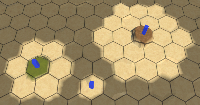
In this section we will add to the map the effect of the fog of war.
Now the series will be created on Unity 2017.1.0.
Now we see that we can and cannot see.
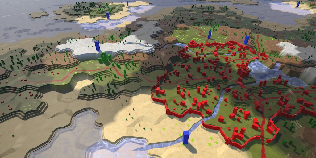
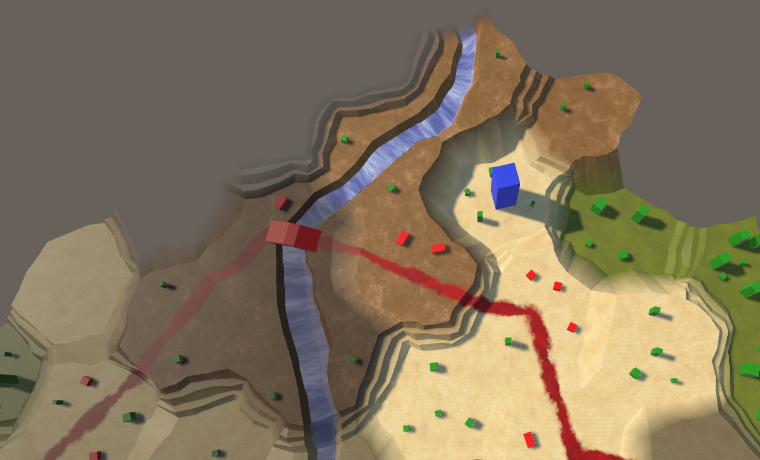
Many strategic games use the concept of fog of war. This means that the player’s vision is limited. He can only see what is close to his units or controlled area. Although we can see the relief, but we do not know what is happening there. Usually invisible relief is rendered darker. To do this, we need to track the visibility of the cell and render it accordingly.
The simplest way to change the appearance of hidden cells is to add a visibility indicator to the mesh data. However, we will have to launch a new triangulation of the relief as visibility changes. This is a bad decision, because during the game the visibility changes constantly.
Often, a rendering technique is used over the top of a semitransparent surface, which partially masks the cells invisible by the player. This method is suitable for relatively flat terrain in combination with a limited viewing angle. But since our relief can contain very varying heights and objects that can be viewed from different angles, for this we need a highly detailed mesh corresponding to the shape of the relief. Such a method would be more expensive than the simplest approach mentioned above.
Another approach is to transfer the data of cells to the shader separately from the relief mesh. This will allow us to perform triangulation only once. Cell data can be transferred using a texture. Changing the texture is a much simpler process than relief triangulation. In addition, the execution of several additional texture samples is faster than rendering a separate translucent layer.
We need a way to control the texture containing the cell data. Let's create a new
When creating or loading a new map, we need to create a new texture with the correct size. Therefore, we add to it an initialization method that creates a texture. We use texture in RGBA format without mip-textures and linear color space. We do not need to mix these cells, so we use point filtering (point filtering). In addition, data should not be minimized. Each pixel of the texture will contain the data of a single cell.
In fact, we do not need to create a new texture every time a new map is created. It is enough to change the size of the texture if it already exists. We will not even need to check if we already have the right size, because
Instead of using cell data one pixel at a time, we use a color buffer and apply data from all cells at a time. To do this, we will use the
The creation and initialization of these cells in the shader should deal with
When creating a new map,
Until now, when changing the properties of a cell, it was necessary to update one or several fragments, but now it may be necessary to update the data of cells. This means that the cells must have a link to the given cells in the shader. To do this, add a property to
In
Now we can force the cells to update their shader data. While we do not track the visibility, but we can use the shader data for something else. The cell relief type defines the texture used when rendering it. It does not affect the geometry of the cell, so we can store the index of the relief type in the cell data, not in the mesh data. This will allow us to get rid of the need for triangulation when changing the type of cell relief.
Add a
We also call it in
To change the cell data, we need to know the cell index. The easiest way to do this is to add the
This index is already in
Now
To apply the data to the texture and transfer it to the GPU, we need to call
To ensure that the data will be updated after creating a new map, we will enable the component after initialization.
Since we now store an index of the type of relief in these cells, we no longer need to include them in the triangulation process. But in order to use these cells, the shader must know which indexes to use. Therefore, it is necessary to store the cell indices in the mesh data, replacing the relief type indices. In addition, we still need the color channel of the mesh to mix cells when using these cells.
Remove outdated common fields
Perform a refactoring-renaming of the list of
Change
Perform the same grouping in
Remove all the methods
Do the same in the appropriate
At this stage, we get a lot of compiler errors in
Let's start by fixing
This method is called in several places. Let's go over them and make it so that the cell index is transmitted there, and not the type of relief.
Next
Let's change the calls of this method so that the cell index is passed to them. Also keep the consistency of variable names.
Now we turn to the methods of angles. These changes are simple, but they need to be made in a large amount of code. First in
Next in
Then in
And a little different in
The previous two methods use
The last method that requires changes is
In order for it to work, we need to specify that we use the cell data for the child element of the fragment's prefab relief.
The terrain uses data cells.
At this stage, the mesh contains cell indices instead of indices of relief types. Since the terrain shader still interprets them as terrain indices, we will see that the first cell is rendered with the first texture, and so on, until the last terrain texture is reached.

The use of cell indices as relief texture indices.
To use these cells, the terrain shader must have access to them. This can be implemented through the shader property. In this case,
After creating the cell texture, we will call the static
When using the shader property, Unity makes the size of the texture available to the shader through the variable textureName_TexelSize . This is a four-component rector containing values opposite to the width and height, as well as the width and height themselves. But when setting the texture to global, this is not the case. Therefore, we will do this on our own using
Create a new shader include file called HexCellData in the materials folder. Inside it we define variables for information about the texture and size of these cells. Also create a function to get the cell data for the given vertex mesh data.
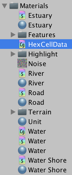
New include file.
Cell indices are stored in
The first step in creating the U coordinate is dividing the cell index by the width of the texture. We can do this by multiplying it by
The result will be a number in the form of ZU, where Z is the index of the string, and U is the U coordinate of the cell. We can extract the string by rounding the number down, and then subtract it from the number to get the U coordinate.
The V coordinate is found by dividing the line by the height of the texture.
Since we are sampling the texture, we need to use the coordinates at the centers of the pixels, and not at their edges. So we guarantee that the correct pixels are sampled. Therefore, after dividing by the size of the texture, we add ½.
This gives us the correct UV coordinates for the index of the first cell stored in the vertex data. But to the top we can have up to three different indices. Therefore, we will do so to
Now that we have all the necessary coordinates of these cells, we can sample
The fourth data component contains a relief type index, which we store directly as a byte. However, the GPU automatically converted it to a floating point value in the range of 0–1. To convert it back to the correct value, multiply it by 255. You can then return the data.
To use this functionality, we include HexCellData in the Terrain shader . Since I placed this shader in Materials / Terrain , I need to use the relative path ../HexCellData.cginc .
In the vertex program, we obtain cell data for all three cell indices stored in the vertex data. Then we assign
At this stage, the map again began to display the correct terrain. The big difference is that editing only relief types no longer leads to new triangulations. If during editing some other cell data is changed, the triangulation will be executed as usual.
unitypackage
Having created the basis of these cells, we can move on to maintaining visibility. To do this, use the shader, the cells themselves and the objects that define the visibility. Notice that the triangulation process knows absolutely nothing about this.
Let's start by telling the Terrain shader about visibility. It will receive visibility data from the vertex program and transmit it to the fragment program using the structure
To store the visibility, we use the first component of the data cells.
A visibility equal to 0 means that the cell is currently invisible. If it were visible, it would have a visibility value of 1. Therefore, we can darken the relief by multiplying the result
The cells are black.
Total darkness is a bust for temporarily invisible cells. So that we could still see the relief, we need to increase the index used for hidden cells. Let's move from 0–1 to ¼ – 1, which can be done using the function

Shaded cells.
For visibility to work, cells must track their visibility. But how does the cell determine if it is visible? We can do this by tracking the number of entities that see it. When someone starts to see a cell, he should report this cell. And when someone stops seeing a cell, he also has to notify her about it. The cell simply keeps track of the number of watchers, whatever these entities are. If the cell has a visibility value of at least 1, then it is visible, otherwise it is invisible. To implement this behavior, we add to the
Next, add to the
We will call this method with increasing and decreasing visibility, changing the value between 0 and 1.
Let's make sure the units can see the cell they occupy. This is implemented by calling
Troops can see where they are.
At last we used visibility! When added to a map, units make their cell visible. In addition, their scope is teleported as they move to their new location. But their field of view remains active when units are removed from the map. To fix this, we will reduce the visibility of their location when destroying units.
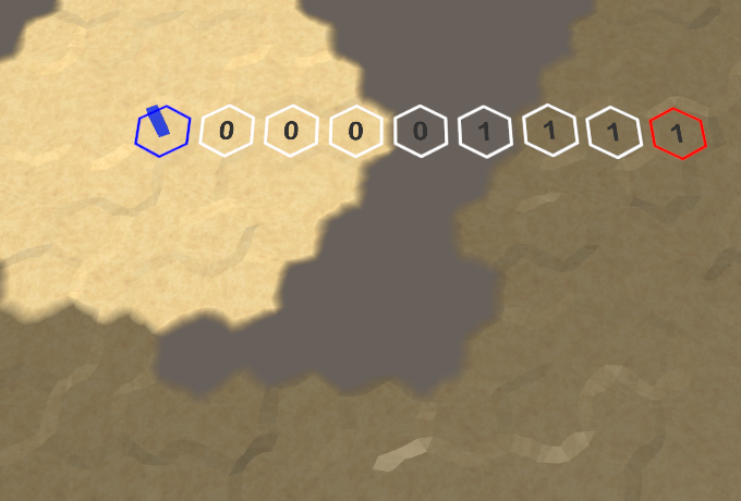
So far we only see the cell in which the squad is located, and this limits the possibilities. We at least need to see the neighboring cells. In the general case, units can see all cells within a certain distance, which depends on the unit.
Let's add to the
At each iteration, the current cell is added to the list. The end cell is no longer there, so the search will never end when it reaches this point. Also get rid of the logic of the moves and the cost of moving. Make it so that the properties
At each step, the distance simply increases by 1. If it exceeds the range, then this cell is skipped. And we do not need search heuristics, so we initialize it with a value of 0. That is, in fact, we returned to the Dijkstra algorithm.
Also add
To use these methods,
When a detachment is added to the grid, it will assign a grid to this property
For a start, there will be enough three-cell visibility range. To do this, add to the
Troops with a range that can overlap.
At the moment, the detachment's field of view after the command to move is immediately teleported to the end point. It would have looked better if the squad and its field of view moved together. The first step to this is that we will no longer set the property
Inside the coroutine
Visibility when moving.
All this works, except for the situation when a new order is given at the moment of movement of the detachment. This leads to teleportation, which should also apply to visibility. To accomplish this, we need to track when moving the current location of the squad.
We will update this location every time we hit a new cell while moving, until the squad gets to the final cell. After which it must be reset.
Now, after completing the turn in,
We also need to correct the visibility after the recompilation, which occurred during the movement of the detachment. If the intermediate location is still known, then reduce the visibility in it and increase the visibility at the end point, and then reset the intermediate location.
unitypackage
Although the color changes of the relief are based on visibility, roads and water are not affected. They look too bright for invisible cells. To apply visibility to roads and water, we need to add cell indexes and blend weights and their mesh data. Therefore, we will check the child elements of Use Cell Data for the Rivers , Roads , Water , Water Shore and Estuaries Prefab fragment.
We will start with the roads. The method is
Another simple method for creating roads is
We now turn to
It remains to add the required arguments to the methods in
Now the mesh data is correct, and we will go to the Road shader . It needs a vertex program and it must contain HexCellData .
Since we do not mix several materials, it will be enough for us to transfer one indicator of visibility to the fragment program.
A new vertex program is enough to receive the data of two cells. We immediately mix their visibility, set it up and add it to the output.
In the fragment program, we only need to add visibility to the color.
Roads with visibility.
It may seem that the visibility has already affected the water, but this is just the surface of the submerged relief. Let's start by applying visibility to open water. For this we need to change
We also need to add data cells to the fans of the triangles near the coast.
The Water shader needs to be changed in the same way as the Road shader , but it needs to combine the visibility of not two, but three cells.
Open water with visibility.
To support the coast, we need to change again
Add the cell data to the quad and the coast triangle. Also pass the indices when calling
Add the necessary parameter to
The shader WaterShore need to make the same changes as in the shader Water Water , mixing the appearance of the three cells.
The Estuary Scheider blends the visibility of two cells, just like the Road shader . He already has a vertex program, because we need him to transmit the UV coordinates of the rivers.
Coast and estuary with visibility.
The last water regions to work with are rivers. Add
We already have these cell indexes in
We will also add support for waterfall indexes that flow into deep water.
And, finally, change it
The River shader needs the same changes as the Road shader .

Rivers with visibility.
unitypackage
Now visibility works for the entire procedurally generated relief, but it does not affect the relief objects yet. Buildings, farms and trees are created from prefabs, not procedural geometry, so we cannot add cell indices and mix weights with their vertices. Since each of these objects belongs to only one cell, we need to determine which cell they are in. If we can do this, we will access the data of the corresponding cells and apply the visibility.
We can already convert the XZ positions of the world into cell indices. This transformation was used to edit the relief and control units. However, the corresponding code is non-trivial. It uses integer operations and requires logic to work with edges. For a shader, this is impractical to apply, so we can bake the main part of the logic into a texture and use it.
We already use a hexagonal-patterned texture to project a grid over the topography. This texture defines a 2 × 2 cell area. Therefore, it is easy to calculate in which area we are. After that, you can apply a texture containing the X and Z offsets to the cells in this area and use this data to calculate the cell in which we are.
Here is a similar texture. The offset by X is stored in its red channel, and the offset by Z is in the green channel. Since it covers a cell area of 2 × 2, we need offsets from 0 and 2. Such data cannot be stored in the color channel, so the offsets are reduced by half. We do not need clear edges of cells, so a small texture is enough.

The texture coordinates of the grid.
Add texture to the project. Set its Wrap Mode to the value of Repeat , as with the other mesh texture. We do not need any blending, so for Blend Mode we choose the value of Point . Also disable Compression so that the data is not distorted. Disable sRGB mode so that when rendering in linear mode no color space transformations are performed. And finally, we do not need mip-textures.
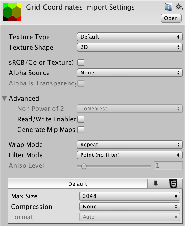
Texture import options.
Create a new shader Feature to add visibility support to objects. This is a simple surface shader with a vertex program. Add HexCellData and transfer the visibility index to the fragment program, and as usual we will take it into account in color. The difference here is that we cannot use
Change all materials of the objects so that they use the new shader, and assign them the texture of the grid coordinates.

Urban with grid texture.
To sample the texture of the grid coordinates in the vertex program, we will again need
As in the Terrain shader , we stretch the UV coordinates so that the texture has the correct aspect ratio corresponding to the grid of hexagons.
We can find out which part of the 2 × 2 cells we are in by taking the value of the UV coordinates rounded down. This forms the basis of the cell coordinates.
To find the coordinates of the cell in which we are, we add the offsets stored in the texture.
Since the grid part is 2 × 2 and the offsets are halved, we need to double the result to get the final coordinates.
Now we have the coordinates of the XZ grid of cells that need to be converted to the UV coordinates of the cells. This can be done simply by moving to the centers of the pixels, and then divided by the size of the textures. So let's add to the HexCellData include file a function for this, which will also be sampled.
Now we can use this function in the vertex shader program Feature .

Objects with visibility.
Finally, visibility affects the entire map, with the exception of units that are always visible. Since we determine the visibility of objects for each vertex, then for an object intersecting the border of the cell, the visibility of the cells being closed by it will be mixed. But objects are so small that they constantly remain inside their cells, even taking into account position distortions. However, some may be part of the vertices in another cell. Therefore, our approach is cheap, but imperfect. This is most noticeable in the case of walls, the visibility of which fluctuates between the appearances of neighboring cells.
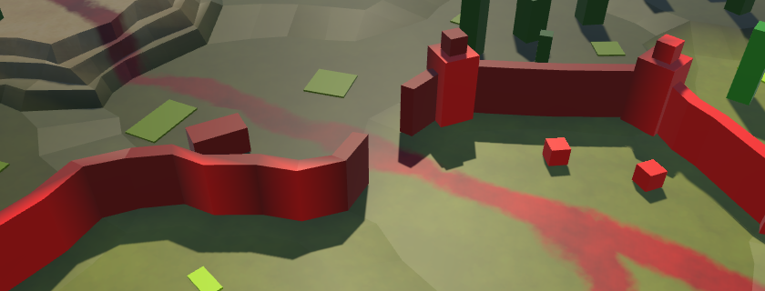
Walls with changing visibility.
Since wall segments are generated procedurally, we can add cell data to their mesh and use the approach we used for the terrain. Unfortunately, the towers are prefabs, so we will still have inconsistencies. In general, the existing approach looks quite good for the simple geometry we use. In the future, we will look at more detailed models and walls, so we will improve the method of mixing their visibility.
unitypackage
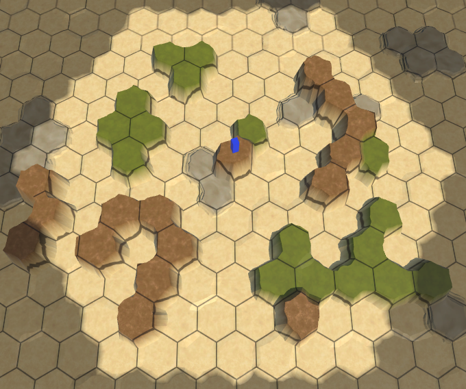
In the previous part, we added the fog of war, which we will now improve to implement a map exploration.
We are ready to explore the world.
The meaning of the study lies in the fact that the cells that are not yet seen are considered to be unknown, and therefore invisible. They should not be shaded, but generally not displayed. Therefore, before adding research support, we will turn on visibility in edit mode.
We can control whether shaders use visibility, using a keyword, as was done with a grid overlay. Let's use the HEX_MAP_EDIT_MODE keyword , which indicates the status of the edit mode. Since several shaders should know about this keyword, we will define it globally using static methods
When HEX_MAP_EDIT_MODE is defined, shaders will ignore visibility. This boils down to the fact that the cell visibility will always be considered equal to 1. Let's add to the beginning of the HexCellData include file a function to filter the cell data depending on the keyword.
Pass through this function the result of both functions
For everything to work, all relevant shaders must receive a multi_compile directive to create variants in case the keyword HEX_MAP_EDIT_MODE is defined. Add the appropriate line to the Estuary , Feature , River , Road , Terrain , Water and Water Shore shaders between the target directive and the first include directive.
Now, when you switch to map editing mode, the fog of war will disappear.
unitypackage
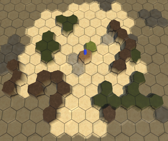
By default, cells should be considered unexplored. They become researched when a squad sees them. After that, they continue to be investigated if a detachment can see them.
To add support for tracking the status of the study, add it to the
The state of the study is determined by the cell itself. Therefore, this property should be set only
The first time, when the visibility of the cell becomes greater than zero, the cell begins to be considered investigated, and therefore the
As in the case of the visibility of the cells, we transfer their state of the study to the shaders through the shader data. In the end, it's just another type of visibility.
Now we can use shaders to visualize the state of the study cells. To make sure everything works as it should, we simply make the unexplored relief black. But first, in order to make the editing mode working, we change it
The Terrain Shader transfers the visibility data of all three possible cells to the fragment program. In the case of the study state, we combine them in the vertex program and transfer the single value to the fragment program. Add the
Now, in the vertex program, when we change the visibility index, we must explicitly access it
After that, we combine the study states and write the result in
The state of the study is now available in the fragment program via
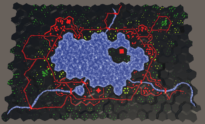
The unexplored relief is now black.
The relief of the unexplored cells is now black. But the objects, roads and water is not affected. However, this is enough to make sure that the study is working.
Now that we have added study support, we need to make sure that the state of the study is taken into account when saving and loading maps. Therefore, we need to increase the version of the map files to 3. To make these changes more convenient, let's add to this
We will use this constant when writing the file version in
As a final step,
And we will read it at the end
To preserve backward compatibility with old save files, we need to skip reading the save state if the file version is less than 3. Let's in this case, by default, the cells will have the status “unexamined”. To do this, we need to add
Now
Now when saving and loading maps, the state of cell exploration will be taken into account.
unitypackage
At the current stage, the unexplored cells are visually indicated by black relief. But in reality, we want these cells to be invisible, because they are unknown. We can make opaque geometry transparent so that it is not visible. However, the Unity surface shader framework was developed without this possibility. Instead of using true transparency, we change the shaders to match the background, which will also make them invisible.
Although the relief is black, we can still recognize it, because it still has specular lighting. To get rid of the lighting, we need to make it perfectly matte black. In order not to affect other surface properties, it is easiest to change the specular color to black. This is possible if you use a surface shader that works with specular, but now we use standard metallic. So let's start by switching the Terrain shader to specular.
Replace the color property _Metallic on property _Specular . By default, its color value should be (0.2, 0.2, 0.2). So we guarantee that it will match the appearance of the metallic version.
We will also change the corresponding shader variables. The color of the specular surface shaders is defined as
Change pragma surface surf from Standard to StandardSpecular . This will force Unity to generate shaders using specular.
Now the function
Now we can obscure the reflections by taking into account

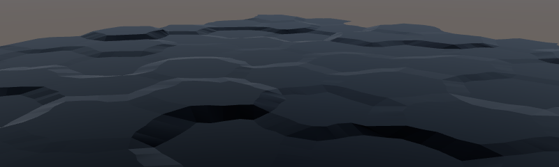
Uncharted relief without reflected light.
As you can see in the picture, the unexplored relief now looks dull black. However, when viewed at a tangent angle, the surfaces turn into a mirror, due to which the relief begins to reflect the surroundings, that is, the skybox.
The unexplored areas still reflect the environment.
To get rid of these reflections, we will consider the unexplored relief completely shaded. This is implemented by assigning a value to
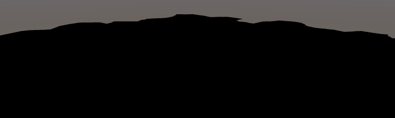
Investigated without reflections.
Now that the unexplored relief ignores all the lighting, you need to make it match the background. Since our camera is always looking from above, the background is always gray. To tell the Terrain shader which color to use, add the _BackgroundColor property , which is set to black by default.
To use this color, we will add it as an emissive light. This is
Since we use the default skybox, the visible background color is actually not the same. In general, the best color would be a little reddish gray. When setting the terrain material, you can use code 68615BFF for Hex Color .
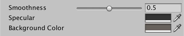
Relief material with gray background color.
In general, it works, although if you know where to look, you can see very weak silhouettes. So that the player could not see them, you can assign a uniform background color of 68615BFF to the camera instead of the skybox.

Camera with a uniform background color.
Now we can not find the differences between the background and unexplored cells. The high unexplored relief can still obscure the low relief studied at low camera angles. In addition, the unexplored parts still cast shadows on the investigated. But these minimal hints can be neglected.
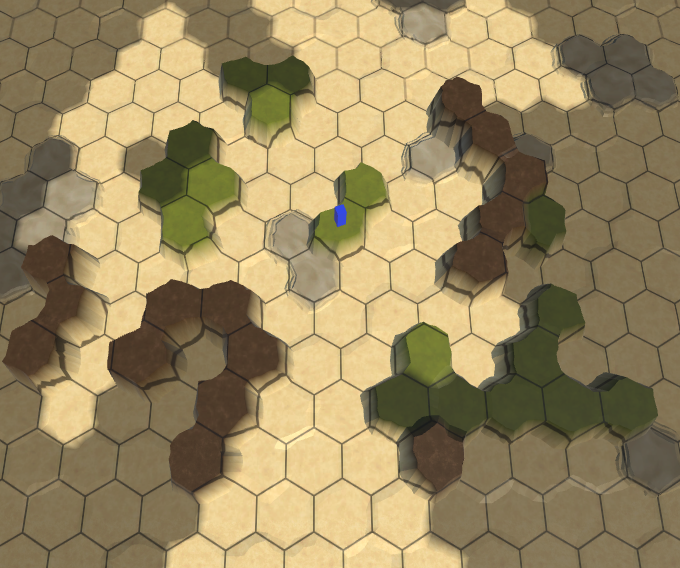
Unexplored cells are no longer visible.
Now we have hidden only the mesh of the relief. It does not act on the rest of the research.
While only the relief is hidden.
Let's now change the Feature shader , which is an opaque shader like Terrain . Turn it into a specular shader and add a background color to it. Let's start with the properties.
Further, pragma surface and variables, as before.
Change it
Modify
Hidden objects of relief.
Next up are the Water and Water Shore shaders . We start by converting them into specular shaders. However, they do not need the background color because they are transparent shaders.
After the conversion, we add to
Water and Water Shore perform in

Hidden water.
We still have shaders Estuary , River and Road . All three are transparent and combine the data of the two cells. Switch them all to specular, and then add them to the
Change the function of the Estuary and River
The Road Shader is a bit different because it uses an extra blend indicator.
Everything is hidden.
unitypackage
Although all unknown is hidden visually, while the state of the study is not taken into account when searching for the path. As a result, the detachments can be ordered to move to the unexplored cells and through them, magically determining which way to go. We need to force squads to avoid unexplored cells.
Navigate through unexplored cells.
Before we go into unexplored cells, let's redo the code to transfer the cost of moving from
Add to the
The method should return the cost of moving. The old code for skipping invalid moves used
Now we need to know when finding the way not only the speed, but also the selected squad. Change accordingly
Since we still need access to the squad’s speed, we’ll add to the
The
Now we will delete the
In order to avoid unexplored cells, it is enough for us to make it so that it
No more units will be able to fall on unexplored cells.
Since unexplored cells are no longer valid endpoints, teams will avoid them when moving to the endpoint. That is, unexplored areas act as barriers that lengthen the path or even make it impossible. We will have to bring the detachments closer to the unknown relief in order to first explore the area.
unitypackage
By adding support for exploring the map, we will improve the calculations and transitions of the scope.
To see further, climb higher.
The cell is either visible or invisible, because it is either in the field of view of the detachment, or not. Even if it seems that a detachment takes some time to move between cells, its field of view jumps from cell to cell instantly. As a result, the visibility of the surrounding cells changes dramatically. The movement of the detachment seems smooth, but changes in visibility are sudden.
Ideally, visibility should also change smoothly. Getting into the field of visibility, the cells should be illuminated gradually, and leaving it, gradually darken. Or maybe you prefer instant transitions? Let's add to the
Even when displaying smooth transitions, the true visibility data still remains binary, that is, the effect is only visual. This means that visibility transitions should deal with
At the moment we set the data of the cells in
It seems that visibility does not work anymore, because while we do nothing with the cells in the list.
Instead of instantly setting the corresponding values of 255 or 0, we will increase / decrease these values gradually. From the rate of change depends on the smoothness of the transition. It should not be very fast and not very slow. A good compromise between beautiful transitions and the convenience of the game is to change within one second. Let's set a constant for this to make it easier to change.
Now
In addition, we need to perform an update while there are transitional cells. Therefore, the code should be included as long as there is something in the list.
Also theoretically, very high frame rates are possible. In combination with a low transition speed, this can give us a delta of 0. To make the change, we will force the minimum of the delta to be 1.
Having received the delta, we can bypass in the cycle all transition cells and update their data. Suppose that we have a method for this
At some point, the cell transition should complete. Suppose the method returns information about whether the transition is still ongoing. When it stops going, we can remove the cell from the list. After this, we must execute the decrement of the iterator in order not to skip the cells.
The order of processing transition cells is not important. Therefore, it is not necessary for us to delete a cell at the current index, which would force
Now we have to create a method
At this stage, we have a cell that is in the process of transition or has already completed it. First, let's check the state of the cell study. If a cell is examined, but its G value is not yet equal to 255, then it is in the process of transition, therefore we will track it.
To perform the transition, we will add a delta cell to the G value. Arithmetic operations do not work with bytes, they are first converted to integer. Therefore, the sum will be in integer format, which needs to be converted to byte.
But before converting you need to make sure that the value does not exceed 255.
Next we need to do the same for visibility, which uses the value of R.
Since the cell can become invisible again, we need to check whether it is necessary to decrease the value of R. This happens in the case when the cell is invisible, but R is greater than zero.
Now
Transitions of visibility.
Transitions work, but there may be duplicate items in the list. This is obtained if the visibility state of the cell changes while it is still in the transition process. For example, when a cell is visible while a unit is moving, only for a short time.
As a result of the appearance of duplicate elements, the cell transition is updated several times per frame, which leads to accelerated transitions and extra work. We can prevent this by checking before adding a cell whether it is already in the list. However, searching the list for each call
For this to work, we need to reset the value of B after the completion of the cell transition.
Transitions without duplicates.
Visibility changes are now gradual, even when loading a map. This is illogical, because the map describes the state in which the cells are already visible, so the transition is irrelevant here. In addition, the execution of transitions for a set of visible cells of a large map may slow down the game after loading. Therefore, before loading cells and squads, let's switch to
So we redefine the initial setting of the instant transition mode, whatever it is. Perhaps it is already disabled, or made configuration option, so remember the original mode and will switch to it after the completion of the work.
unitypackage
For the time being we used a constant field of view equal to three for all units, but in reality it is more complicated. In general, we cannot see an object for two reasons: either we are hampered by some kind of obstacle, or the object is too small or far. In our game, we implement only the limitation of the scope.
We cannot see what is on the opposite side of the Earth, because the planet is obscuring our view. We can only see to the horizon. Since the planet can be approximately considered as a sphere, the higher the viewpoint, the more surface we can see, that is, the horizon depends on the height.
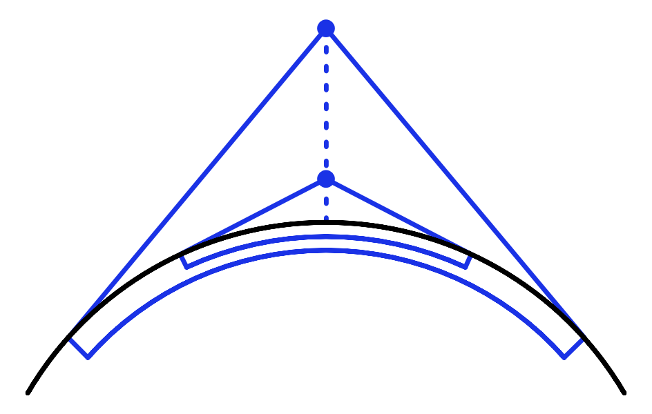
The horizon depends on the height of the viewpoint.
The limited scope of our units mimics the horizon effect created by the curvature of the Earth. The range of their review depends on the size of the planet and the scale of the map. At least this is the logical explanation. But the main reason for reducing the scope is the gameplay, a limitation called the fog of war. However, understanding the physics underlying the field of view, we can conclude that a high point of view should have strategic value, because it postpones the horizon and allows you to look beyond lower obstacles. But so far we have not implemented it.
To take altitude into account when determining the scope, we need to know altitude. This will be the usual height or water level, depending on whether the land cell or the water cell. Let's add for this to the
But if height affects the field of visibility, then when the cell's height changes, the situation with visibility can also change. Since the cell has blocked or now blocks the scope of several units, it is not so easy to determine what needs to be changed. This task cannot be solved by the cell itself, so let it report a change in the situation
The same applies to
Now we need to create a method
To reset the visibility values of all the cells, you need to have access to them, which is
Go to
Now we need to add to the
After clearing all visibility data,
To make it work, we will perform a refactoring-rename
Due to this, the visibility data will be reset and remain correct after changing the height of the cell view. But it is likely that we will change the rules for defining the scope and launch recompilation in Play mode. To make the scope of visibility change on its own, let's launch a reset
Now you can change the scope code and see the results while remaining in Play mode.
The calculation of the scope is determined
Use altitude as a scope.
Applying the viewing height as an area of view correctly works only when all other cells are at zero height. But if all cells have the same height as the viewpoint, then the field of view should be zero. In addition, cells with high heights should block the visibility of low cells behind them. So far, none of this has been implemented.
The scope is not obstructed.
The most correct way to determine the scope would be to test the emission of rays, but it would quickly become costly and could still produce strange results. We need a quick solution that creates fairly good results that do not have to be perfect. In addition, it is important that the rules for determining the scope are simple, intuitive and predictable for players.
Our solution will be the following: when determining the visibility of a cell, we will add the height of the view of the neighboring cell to the covered distance. In fact, it reduces the scope when we look at these cells, and if they are skipped, it will not allow us to reach the cells behind them.
High cells block the view.
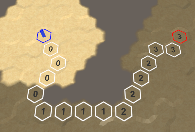
Now it seems that the high cells block the view to the low ones, however, sometimes the field of view penetrates through them, although it seems that this should not be. This happens because the search algorithm still finds the path to these cells, bypassing the blocking cells. As a result, it looks as if our field of view can go around obstacles. To avoid this, we need to ensure that only the shortest paths are taken into account when determining the visibility of the cell. This can be done by dropping paths that are longer than necessary.

We use only the shortest paths.
So we corrected most obviously erroneous cases. For nearby cells, this works well, because there are only the shortest paths to them. Farther cells have more options for the paths, so over long distances there may still be a bending around the visibility. This will not be a problem if the areas of visibility remain small, and the differences of neighboring heights are not too large.
And finally, instead of replacing the transmitted field of view, add to it the height of the review. The detachment's own field of view denotes its height, height of flight, or reconnaissance capabilities.
A full-field view at a low point of view.
That is, the final rules of visibility refer to the vision when moving along the shortest path to the field of view, taking into account the difference in the height of the cells relative to the point of view. When a cell is out of scope, it blocks all paths through it. As a result, high observational points, the view from which does not interfere with anything, become strategically valuable.
unitypackage
The last issue with visibility concerns the edges of the map. The relief ends abruptly and without transitions, because the cells on the edge have no neighbors.
Marked edge of the map.
Ideally, the visual display of unexplored areas and the edges of the map should be the same. We can achieve this by adding special cases in the triangulation of edges, when they have no neighbors, but this will require additional logic, and we will have to work with the missing cells. Therefore, this solution is not trivial. An alternative approach is to force the boundary cells of the map to be unexamined, even if they are within the scope of the detachment. This approach is much simpler, so let's use it. It also allows you to mark as unexamined and other cells, making it easier to achieve the creation of uneven edges of the map. In addition, the hidden cells on the edges allow you to create roads and rivers entering and outgoing from the map of rivers and roads, because their end points will be out of scope.Also using this solution, you can add incoming and outgoing units from the map.
To indicate that a cell can be examined, we add it to the
The cell can now be visible if it is examined, so we will change the property
The same applies to
Hide the edge of a rectangular map in the method
Now the maps are darkened around the edges, hiding behind them huge unexplored spaces. As a result, the size of the studied map area decreases in each dimension by two.
Uncharted card edge.
Finally, if a cell cannot be explored, then it should interfere with visibility. Change
unitypackage
This part of the tutorial will be the beginning of a series on procedural map generation.
This part is created in Unity 2017.1.0.

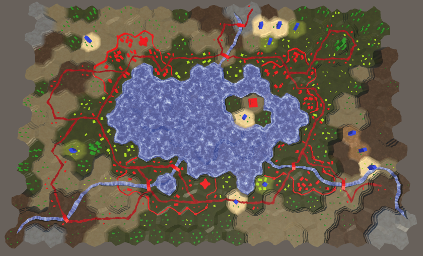
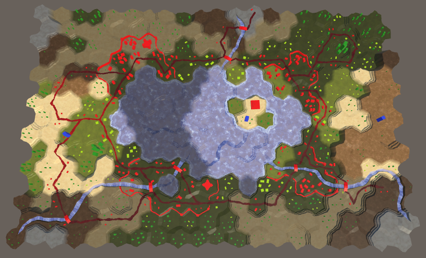
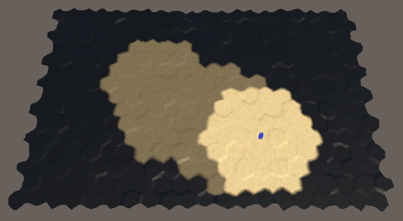
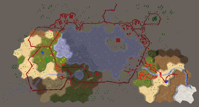
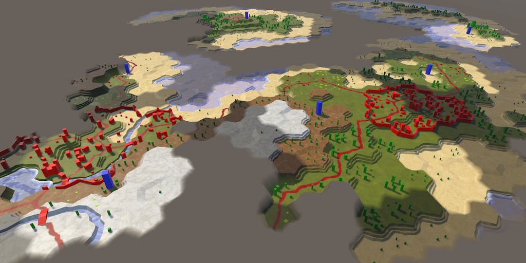
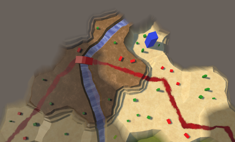
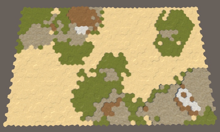
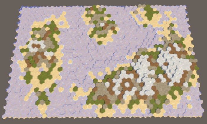
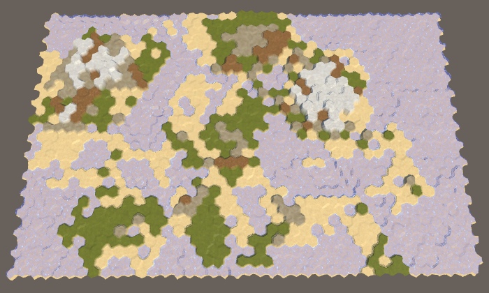
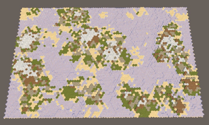
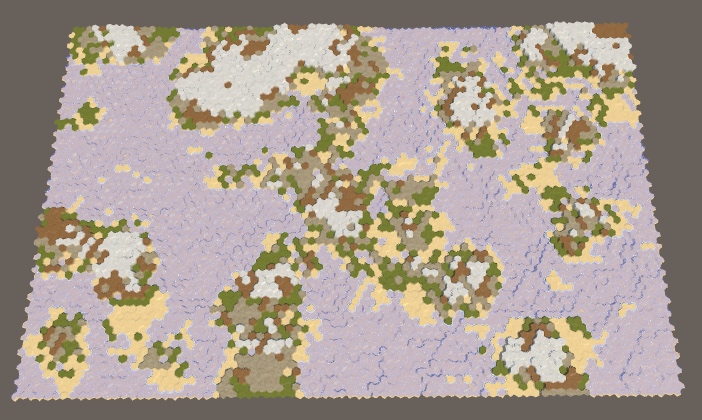
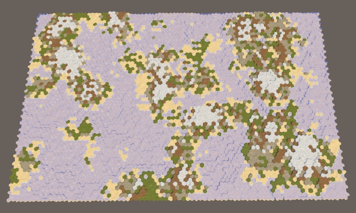
One of the many generated maps.
Although we can create any map, it takes a lot of time. It would be convenient if the application could help the designer, generating maps for him, which he can then change to his taste. You can take one more step and completely get rid of creating the design manually, completely transferring the responsibility of generating the finished card to the application. Thanks to this, it will be possible to play the game every time with a new card and each game session will be different. To make all this possible, we must create an algorithm for generating maps.
The type of generation algorithm required depends on the type of maps required. There is no one right approach, you always have to find a compromise between plausibility and playability.
In order for the card to be believable, it must appear to the player to be quite possible and real. This does not mean that the map should look like a part of our planet. It may be another planet or a completely different reality. But if it must denote the relief of the Earth, it must at least partially resemble it.
Playability is related to how the cards match the gameplay. Sometimes it comes into conflict with the plausibility. For example, although the mountain ranges may look beautiful, they at the same time severely restrict movement and survey of units. If this is undesirable, then you have to do without mountains, which will reduce the likelihood and limit the expressiveness of the game. Or we can save the mountains, but reduce their impact on the gameplay, which is also able to reduce the likelihood.
In addition, you need to consider feasibility. For example, you can create a very realistic land-like planet by simulating tectonic plates, erosion, rain, volcanic eruptions, the impact of meteorites and the moon, and so on. But the development of such a system will take a long time. In addition, the generation of such a planet may take a long time, and players will not want to wait a few minutes before starting a new game. That is, simulation is a powerful tool, but it has its price.
In games, tradeoffs between plausibility, playability and feasibility are often used. Sometimes these compromises are invisible and seem completely normal, and sometimes they look random, inconstant or chaotic, depending on the decisions made during the development process. This applies not only to the generation of maps, but when developing a procedural map generator, you need to treat this with particular attention. You can spend a lot of time creating an algorithm that generates beautiful cards that will be useless for the game you are creating.
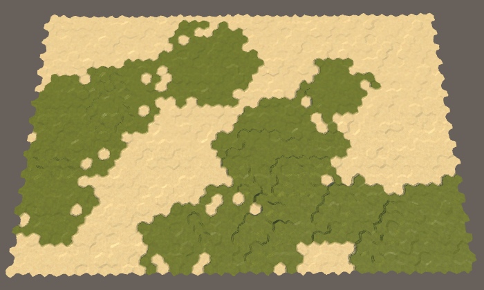
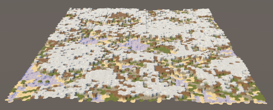
In this series of tutorials, we will create an earth-like relief. It should look interesting, with large variability and the lack of large homogeneous areas. The scale of the relief will be large, the maps will cover one or more continents, areas of the oceans, or even the whole planet. We need control over geography, including the land massifs, climate, the number of regions and uneven terrain. In this part we will lay the foundation for the creation of sushi.
We will focus on the map, and not on the gameplay, so it will be more convenient to launch the application in edit mode. Thanks to this, we can immediately see the cards. Therefore, we change it by
Since quite a lot of code is needed to generate procedural maps, we will not add it directly to
The generator needs a reference to the grid, so we will add a common field for it. In addition, we add a general method
Add an object with the component to the scene
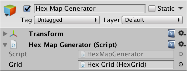
Map Generator Object
We will modify it

Menu new card with a switch.
Give the menu a link to the map generator. Then we make it, if necessary, call the

Connect to the generator.
In order for the generator to work, it needs access to the cells. We
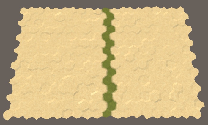
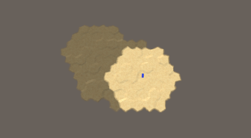
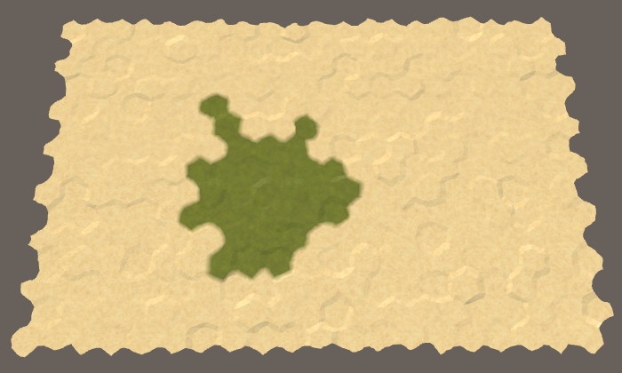
A column of grass on a small map.
unitypackage
When generating a map, we start completely without sushi. One can imagine that the whole world is flooded with one huge ocean. Land is created when part of the ocean floor is pushed up so that it rises above the water. We need to decide how much sushi should be created in such a way, where it will appear and what form it will have.
Let's start small - we will raise one piece of land above the water. Create a method for this
For the time being, we simply use the type of relief “grass” to denote raised land, while the original relief “sand” refers to the ocean. Let's force us
To get a random cell, add a method
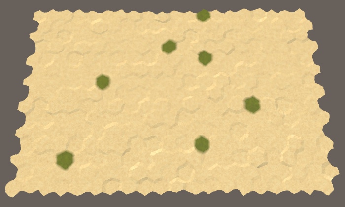
Seven random sushi cells.
Since in the end we may need a lot of random cells or cycle around all the cells several times, let's track the number of cells in the cell itself
So far, we turn seven random cells into land, and they can be anywhere. Most likely they do not form a single piece of land. In addition, we can select the same cells several times, so we will have a smaller volume of land. To solve both problems, without limitation, we will select only the first cell. After that, we need to select only those cells that are next to the ones selected earlier. These constraints are similar to the path finding constraints, so we use the same approach here.
Add a
We check that the priority queue exists before we need it.
After creating a new map, the search boundary for all cells is zero. But if we are going to look for cells in the process of generating a map, then we will increase their search boundary in this process. If we perform many search operations, they may be ahead of the search boundary phase recorded
Now I
After this, the search cycle will be mostly familiar to us. In addition, in order to continue the search until the border is empty, we need to stop when the fragment reaches the desired size, so we’ll track it. At each iteration, we will retrieve the next cell from the queue, set its relief type, increase its size, and then bypass the neighbors of this cell. All neighbors are simply added to the border if they have not been added yet. We do not need to make any changes or comparisons. After completion, you need to clear the border.
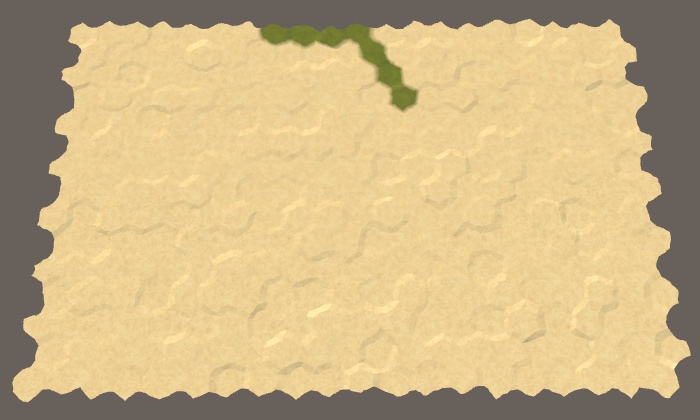
Line of cells.
We got a single piece of the right size. It will be smaller only if there are not enough cells. Due to the way the border is filled, the plot always consists of a line going to the north-west. It changes direction only when it reaches the edge of the map.
Land plots rarely resemble lines, and if they do, they are not always oriented in the same way. To change the shape of the plot, we need to change the priorities of the cells. The first random cell can be used as the center of the plot. Then the distance to all other cells will be relative to this point. So we will give a higher priority to cells that are closer to the center, thanks to which the plot will grow not as a line, but around the center.
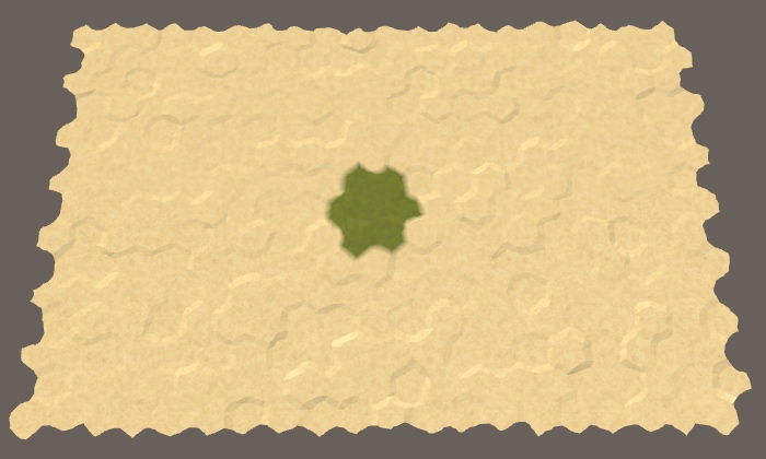
The accumulation of cells.
Indeed, now our seven cells are beautifully packed in a compact hexagonal area, if the central cell does not end up on the edge of the map. Let's try now to use the size of a plot of 30.
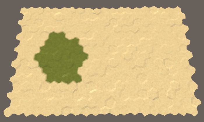
Sushi in 30 cells.
We again obtained the same shape, although it did not suffice to obtain a regular hexagon of cells. Since the radius of the plot is larger, it is more likely to be close to the edge of the map, which will force it to take another shape.
We do not want all areas to look the same, so we’ll slightly change the priorities of the cells. Every time we add a neighboring cell to the border, if the next number is
Distorted plot.
Increasing the cell search heuristics, we made it visit later than expected. At the same time, other cells that are one step further from the center will be visited earlier, unless they have also increased the heuristics. This means that if we increase the heuristics of all cells by one magnitude, this will not affect the map in any way. That is, threshold 1 will have no effect, as well as threshold 0. And threshold 0.8 will be equivalent to 0.2. That is, the probability of 0.5 makes the search process the most “trembling”.
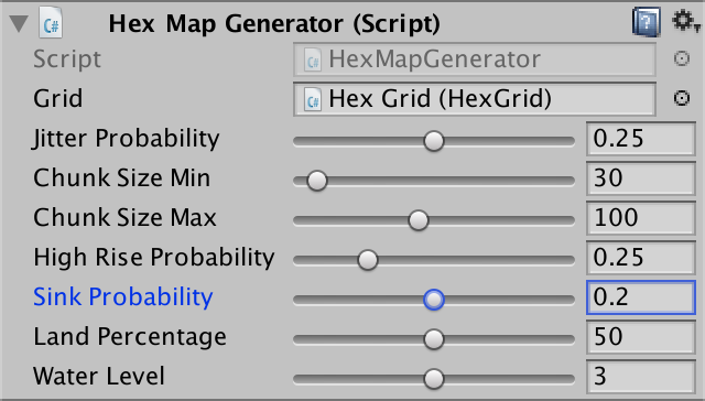
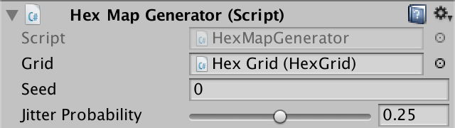
The appropriate amount of vibration depends on the type of relief you need, so let's make it customizable. Add to the generator a common float field
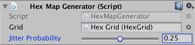
Probability of fluctuations
Now, to decide when the heuristics should be equal to 1, we use probability instead of a constant value.
We use heuristic values of 0 and 1. Although larger values can be used, this will greatly worsen the deformation of the sections, most likely turning them into a bunch of bands.
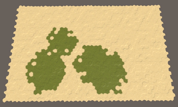
We will not be limited to the generation of one land plot. For example, put a call

Five plots of land.
Although now we are generating five plots of 30 cells each, but we do not necessarily get exactly 150 land cells. Since each section is created separately, they do not know about each other, so they can intersect. This is normal because it can create more interesting landscapes than just a set of isolated sites.
To increase the variability of land, we can also change the size of each section. Add two integer fields to control the minimum and maximum sizes of sections. Let us assign them a rather large interval, for example, 20–200. I will make the standard minimum equal to 30, and the standard maximum - 100.
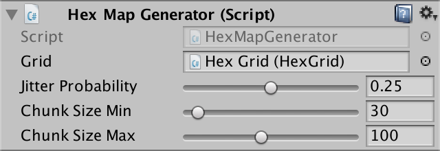
The interval sizes of the plots.
We use these fields to randomly determine the size of the area when calling
Five sites with random sizes on the middle map.
While we can not particularly control the amount of sushi generated. Although we can add the option for configuring the number of parcels, the dimensions of the parcels themselves are random and may slightly or strongly intersect. Therefore, the number of plots does not guarantee getting the required amount of sushi on the map. Let's add an option to directly control the percentage of land, expressed as an integer. Since 100% of land or water is not very interesting, we will limit it to an interval of 5–95, with a default value of 50.

Percent Sushi
To ensure the creation of the required amount of land, we just need to continue to raise the terrain until a sufficient amount is obtained. To do this, we need to control the process, which will complicate the generation of land. Therefore, let's replace the existing cycle of raising sites to call a new method
The amount should decrease each time the cell is removed from the border and turns into land. If after this the entire amount is spent, then we must stop searching and complete the area. In addition, it should be done only when the current cell is not land yet.
Now it

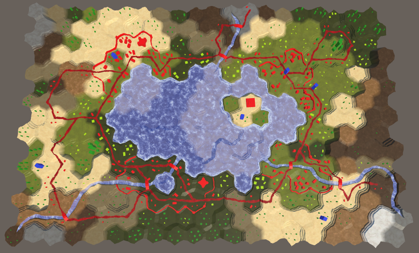
Exactly half of the map was dry.
unitypackage
Land is not just a flat plate bounded by the coastline. She has a varying height, containing hills, mountains, valleys, lakes, and so on. Large elevation differences exist due to the interaction of slowly moving tectonic plates. Although we will not pretend it, our land areas must somehow resemble such plates. The plots do not move, but can intersect. And we can use it.
Each parcel denotes a portion of land pushed from the bottom of the ocean. Therefore, let us constantly increase the height of the current cell in
Drying with heights.
We got heights, but they are difficult to see. You can make them more legible if you use your own type of relief for each level of height, like geographic layering. We will do this only to make the heights more noticeable, so you can simply use the height level as an index of the relief.
Instead of updating the cell type of the cell each time you change the height, let's create a separate method
We will call this method after creating sushi.
Now it
Stratification layers.
Let's explicitly indicate which cells are water or land by setting the water level for all cells to 1. Make it in
Now, to denote the layers of land, we can use all types of relief. All underwater cells will remain sand, as well as the lowest land cells. This can be done by subtracting the water level from the height and using the value as an index of the type of relief.

Drying and water.
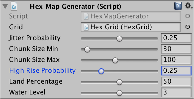
We are not limited to one water level. Let's make it customizable using a common field with an interval of 1–5 and a value of 3 by default. Use this level when initializing cells.
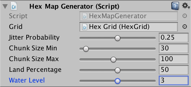
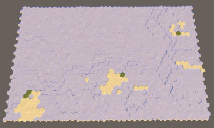
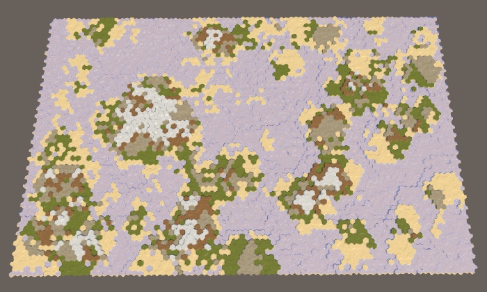
The water level is 3.
When the water level is 3, we have less land than we expected. This happens because it
Using higher water levels leads to. that cells do not become dry immediately. When the water level is 2, the first section will still remain under water. The ocean floor has risen, but it still remains under water. Land is formed only when crossing at least two sections. The higher the water level, the more sections must intersect to create sushi. Therefore, as the water level rises, the land becomes more chaotic. In addition, when more sites are needed, there is a higher probability that they will intersect on already existing land, which will cause mountains to occur more often and flat land less often, as in the case of using smaller sites.

Water levels are 2–5, land is always 50%.
unitypackage
While we were raising the sites up one level of height at a time, but we are not obliged to limit ourselves to this.
Although each section increases the height of its cells by one level, there may be breaks. This happens when they touch the edges of two sections. This may create isolated cliffs, but long cliff lines will be rare. We can increase the frequency of their appearance by increasing the height of the section by more than one step. But this should be done only for a certain proportion of sites. If all areas go high, it will be very difficult to move along the relief. So let's make this parameter customizable using a probability field with a default value of 0.25.
The probability of a strong rise of the cells.
Although we can use any increase in height for elevated areas, this quickly goes out of control. The height difference 2 already creates cliffs, so this is enough. Since you can skip a height equal to the level of the water, we need to change the way that the cell is turned into land. If it was below the water level, and now it is at the same level or higher, then we have created a new land cell.


The probabilities of a strong increase in height are 0.25, 0.50, 0.75 and 1.
Land does not always rise, sometimes it falls. When the land falls low enough, it is filled with water and it is lost. While we are not doing this. Since we are only pushing the areas up, the land usually looks like a set of fairly round areas that are mixed together. If we sometimes lower the plot down, we get more varying forms.
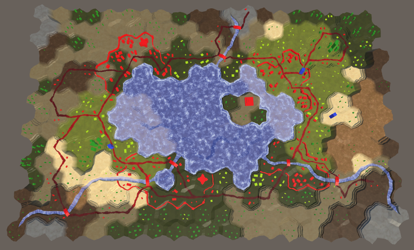
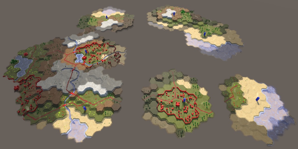
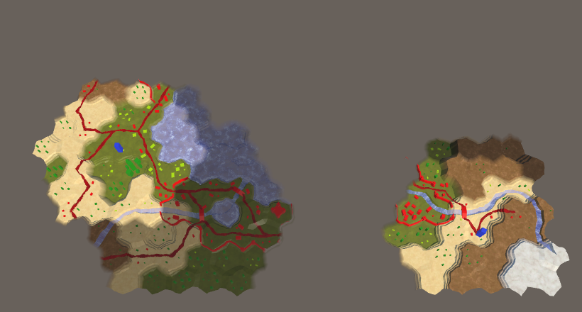
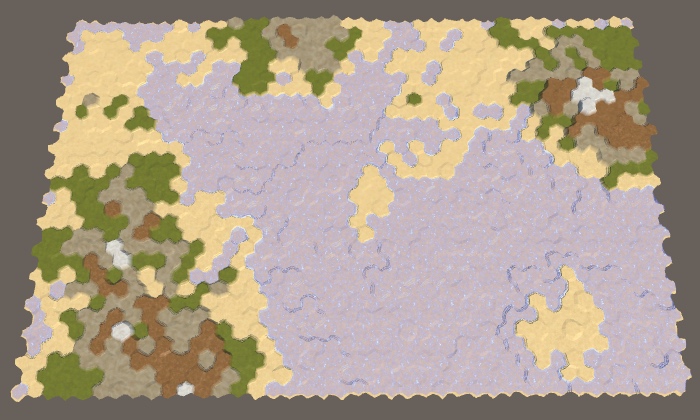
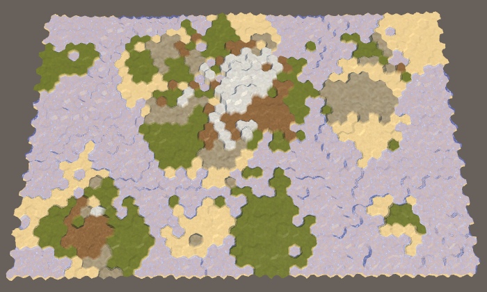
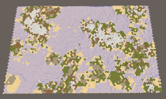
Large map without sunken sushi.
We can control the frequency of descending land using another probability field. Since the lowering can destroy the land, the probability of lowering should always be lower than the probability of raising. Otherwise, it may take a very long time to get the desired land percentage. So let's use the maximum probability of dropping 0.4 with a default value of 0.2.
The probability of lowering.
Lowering the plot is like lifting, with some differences. Therefore, duplicate the method
Now at each iteration inside

The probability of lowering 0.1, 0.2, 0.3 and 0.4.
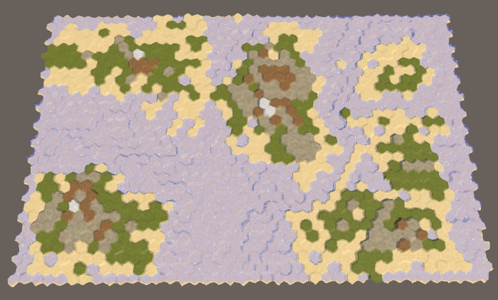
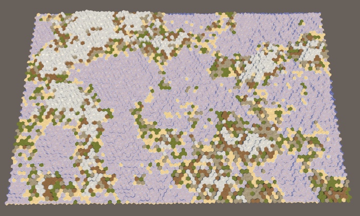
At the current stage, we can potentially impose on each other many sections, sometimes with several increases in height, some of which can fall and then rise again. At the same time, we can create very high and sometimes very low heights, especially when a high percentage of land is needed.

Huge heights at 90% land.
To limit height, let's add a custom minimum and maximum. A reasonable minimum will be somewhere between −4 and 0, and an acceptable maximum may be in the range of 6–10. Let the default values be −2 and 8. If you manually edit the map, they will be outside the allowed limit, so you can change the UI slider of the editor, or leave it as it is.
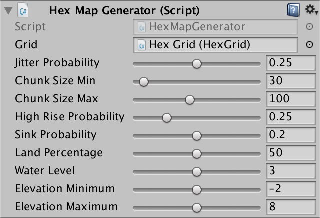
Minimum and maximum height.
Now
Let's do the same in
Limited height with 90% sushi.
At this stage, the save and load code cannot handle negative heights, because we store the height as byte. A negative number is converted when saved to a large positive. Therefore, when saving and loading the generated map, very high ones may appear in place of the original underwater cells.
We can add support for negative height by storing it as an integer, not byte. However, we still do not need to provide support for multiple levels of height. In addition, we can shift the stored value by adding 127. This will allow you to correctly maintain heights in the range −127–128 within one byte. Change
Since we have changed the way we save the map data, let's increase it
And finally, we change it
unitypackage
Now we can create a variety of maps. When generating each new result will be random. Using configuration options, we can control only the characteristics of the map, but not the most accurate form. But sometimes we need to recreate the exact same map again. For example, to share with a friend a beautiful card, or start again after manually editing it. In addition, it is useful in the development of the game, so let's add this feature.
To make the map generation process unpredictable, we use
Next we need to make available the seed used to generate the last map. This is done using a common integer field.
Display seed.
Now we need the seed value to initialize
Since after completion we restore the random state, then if we immediately generate another card, we will end up with the same seed value. In addition, we do not know how the initial random state was initialized. Therefore, although it can serve as an arbitrary starting point, we need something more to randomize it with each call.
There are various ways to initialize random number generators. In this case, you can simply combine several arbitrary values that vary in a wide range, that is, the probability of re-generating the same card will be low. For example, use the bottom 32 bits of the system time, expressed in cycles, plus the current application execution time. We combine these values using the bitwise exclusive OR operation so that the result is not very large.
The resulting number can be negative, which for the generally available value of the seed does not look very nice. We can make it strictly positive by using bitwise masking with a maximum integer value that zeroes the sign bit.
We still generate random maps, but now we can see which seed value was used for each of them. To recreate the same card again, we must order the generator to use the same seed value again, and not create a new one. We do this by adding a switch using a boolean field.
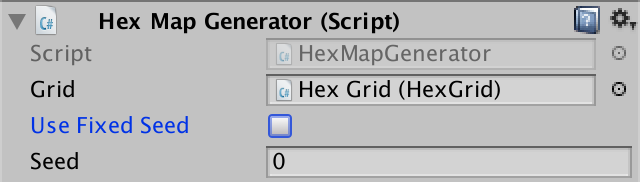
The option of using a constant seed.
If a permanent seed is selected, then we simply skip the new seed generation
Now we can copy the seed value of the map we like and save it somewhere to generate it in the future. Do not forget that we will get the same card only if we use exactly the same generator parameters, that is, the same card size, as well as all other configuration options. Even a small change in these probabilities can create a completely different map. Therefore, besides seed, we need to remember all the settings.
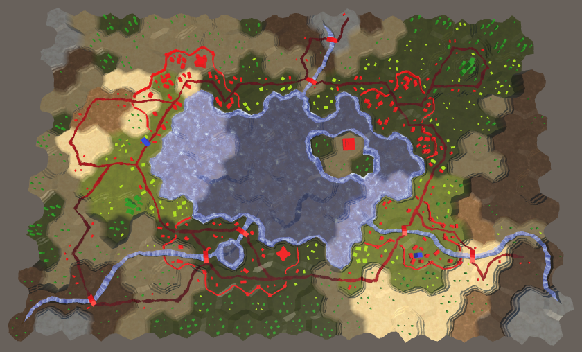
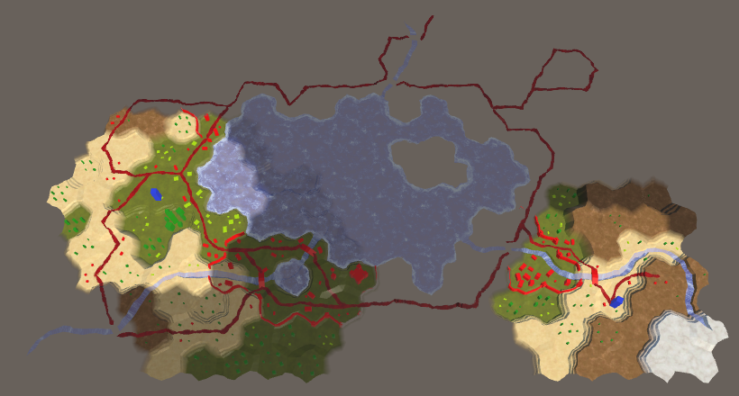
Large cards with values of seed 0 and 929396788, standard parameters.
unitypackage
Parts 4-7: bumps, rivers and roads
Parts 8-11: water, landforms and walls
')
Parts 12-15: saving and loading, textures, distances
Parts 16-19: Pathfinding, Player Squads, Animations
Parts 20-23: fog of war, map exploration, procedural generation
Parts 24-27: water cycle, erosion, biomes, cylindrical map
Part 20: Fog of War
- Store cell data in a texture.
- Change terrain types without triangulation.
- We trace visibility.
- We darken everything invisible.
In this section we will add to the map the effect of the fog of war.
Now the series will be created on Unity 2017.1.0.
Now we see that we can and cannot see.
Cell data in the shader
Many strategic games use the concept of fog of war. This means that the player’s vision is limited. He can only see what is close to his units or controlled area. Although we can see the relief, but we do not know what is happening there. Usually invisible relief is rendered darker. To do this, we need to track the visibility of the cell and render it accordingly.
The simplest way to change the appearance of hidden cells is to add a visibility indicator to the mesh data. However, we will have to launch a new triangulation of the relief as visibility changes. This is a bad decision, because during the game the visibility changes constantly.
Often, a rendering technique is used over the top of a semitransparent surface, which partially masks the cells invisible by the player. This method is suitable for relatively flat terrain in combination with a limited viewing angle. But since our relief can contain very varying heights and objects that can be viewed from different angles, for this we need a highly detailed mesh corresponding to the shape of the relief. Such a method would be more expensive than the simplest approach mentioned above.
Another approach is to transfer the data of cells to the shader separately from the relief mesh. This will allow us to perform triangulation only once. Cell data can be transferred using a texture. Changing the texture is a much simpler process than relief triangulation. In addition, the execution of several additional texture samples is faster than rendering a separate translucent layer.
What about using shader arrays?
You can also transfer cell data to a shader using an array of vectors. However, shader arrays have a size limit of thousands of bytes, and textures can contain millions of pixels. To support large maps, we will use textures.
Cell Data Management
We need a way to control the texture containing the cell data. Let's create a new
HexCellShaderData component that will do this. using UnityEngine; public class HexCellShaderData : MonoBehaviour { Texture2D cellTexture; } When creating or loading a new map, we need to create a new texture with the correct size. Therefore, we add to it an initialization method that creates a texture. We use texture in RGBA format without mip-textures and linear color space. We do not need to mix these cells, so we use point filtering (point filtering). In addition, data should not be minimized. Each pixel of the texture will contain the data of a single cell.
public void Initialize (int x, int z) { cellTexture = new Texture2D( x, z, TextureFormat.RGBA32, false, true ); cellTexture.filterMode = FilterMode.Point; cellTexture.wrapMode = TextureWrapMode.Clamp; } Should the size of the texture match the size of the map?
No, it just needs to have enough pixels to hold all the cells. If the map exactly matches the size of the map, then a non-power-of-two (NPOT) texture will most likely be created, and such a texture format is not the most efficient. Although we can customize the code to work with textures as large as a power of two, this is a minor optimization that complicates access to cell data.
In fact, we do not need to create a new texture every time a new map is created. It is enough to change the size of the texture if it already exists. We will not even need to check if we already have the right size, because
Texture2D.Resize is smart enough to do it for us. public void Initialize (int x, int z) { if (cellTexture) { cellTexture.Resize(x, z); } else { cellTexture = new Texture2D( cellCountX, cellCountZ, TextureFormat.RGBA32, false, true ); cellTexture.filterMode = FilterMode.Point; cellTexture.wrapMode = TextureWrapMode.Clamp; } } Instead of using cell data one pixel at a time, we use a color buffer and apply data from all cells at a time. To do this, we will use the
Color32 array. If necessary, we will create a new instance of the array at the end of Initialize . If we already have an array of the correct size. then we clear its contents. Texture2D cellTexture; Color32[] cellTextureData; public void Initialize () { … if (cellTextureData == null || cellTextureData.Length != x * z) { cellTextureData = new Color32[x * z]; } else { for (int i = 0; i < cellTextureData.Length; i++) { cellTextureData[i] = new Color32(0, 0, 0, 0); } } } What is Color32?
Standard uncompressed RGBA textures contain four byte pixels. Each of the four color channels receives byte, that is, they have 256 possible values. When using the Unity
The
Color structure, its floating point components in the interval 0–1 are converted to bytes in the interval 0–255. When sampling, the GPU performs the inverse transform.The
Color32 structure works directly with bytes, so they take up less space and do not require conversion, which increases the efficiency of their use. Since we store cell data instead of colors, it would be more logical to work directly with raw texture data, rather than with Color .The creation and initialization of these cells in the shader should deal with
HexGrid . Therefore, add the cellShaderData field to cellShaderData and create a component inside Awake . HexCellShaderData cellShaderData; void Awake () { HexMetrics.noiseSource = noiseSource; HexMetrics.InitializeHashGrid(seed); HexUnit.unitPrefab = unitPrefab; cellShaderData = gameObject.AddComponent<HexCellShaderData>(); CreateMap(cellCountX, cellCountZ); } When creating a new map,
cellShaderData should also be initiated. public bool CreateMap (int x, int z) { … cellCountX = x; cellCountZ = z; chunkCountX = cellCountX / HexMetrics.chunkSizeX; chunkCountZ = cellCountZ / HexMetrics.chunkSizeZ; cellShaderData.Initialize(cellCountX, cellCountZ); CreateChunks(); CreateCells(); return true; } Modifying Cell Data
Until now, when changing the properties of a cell, it was necessary to update one or several fragments, but now it may be necessary to update the data of cells. This means that the cells must have a link to the given cells in the shader. To do this, add a property to
HexCell . public HexCellShaderData ShaderData { get; set; } In
HexGrid.CreateCell assign this property to the shader data component. void CreateCell (int x, int z, int i) { … HexCell cell = cells[i] = Instantiate<HexCell>(cellPrefab); cell.transform.localPosition = position; cell.coordinates = HexCoordinates.FromOffsetCoordinates(x, z); cell.ShaderData = cellShaderData; … } Now we can force the cells to update their shader data. While we do not track the visibility, but we can use the shader data for something else. The cell relief type defines the texture used when rendering it. It does not affect the geometry of the cell, so we can store the index of the relief type in the cell data, not in the mesh data. This will allow us to get rid of the need for triangulation when changing the type of cell relief.
Add a
HexCellShaderData method to RefreshTerrain to simplify this task for a specific cell. Let's leave this method blank for now. public void RefreshTerrain (HexCell cell) { } HexCell.TerrainTypeIndex so that it HexCell.TerrainTypeIndex this method and does not order to update the fragments. public int TerrainTypeIndex { get { return terrainTypeIndex; } set { if (terrainTypeIndex != value) { terrainTypeIndex = value; // Refresh(); ShaderData.RefreshTerrain(this); } } } We also call it in
HexCell.Load after getting the cell relief type. public void Load (BinaryReader reader) { terrainTypeIndex = reader.ReadByte(); ShaderData.RefreshTerrain(this); elevation = reader.ReadByte(); RefreshPosition(); … } Cell index
To change the cell data, we need to know the cell index. The easiest way to do this is to add the
Index property to HexCell . It will designate the cell index in the list of map cells, which corresponds to its index in the given cells in the shader. public int Index { get; set; } This index is already in
HexGrid.CreateCell , so just assign it to the created cell. void CreateCell (int x, int z, int i) { … cell.coordinates = HexCoordinates.FromOffsetCoordinates(x, z); cell.Index = i; cell.ShaderData = cellShaderData; … } Now
HexCellShaderData.RefreshTerrain can use this index to set cell data. Let's keep the index of the relief type in the alpha component of its pixel, simply converting the type to byte. This will support up to 256 types of terrain, which will be quite enough for us. public void RefreshTerrain (HexCell cell) { cellTextureData[cell.Index].a = (byte)cell.TerrainTypeIndex; } To apply the data to the texture and transfer it to the GPU, we need to call
Texture2D.SetPixels32 , and then Texture2D.Apply . As in the case of fragments, we will postpone these operations on LateUpdate , so that you can perform them no more than once per frame, regardless of the number of changed cells. public void RefreshTerrain (HexCell cell) { cellTextureData[cell.Index].a = (byte)cell.TerrainTypeIndex; enabled = true; } void LateUpdate () { cellTexture.SetPixels32(cellTextureData); cellTexture.Apply(); enabled = false; } To ensure that the data will be updated after creating a new map, we will enable the component after initialization.
public void Initialize (int x, int z) { … enabled = true; } Cell Index Triangulation
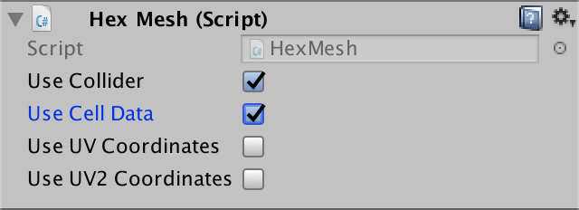
Since we now store an index of the type of relief in these cells, we no longer need to include them in the triangulation process. But in order to use these cells, the shader must know which indexes to use. Therefore, it is necessary to store the cell indices in the mesh data, replacing the relief type indices. In addition, we still need the color channel of the mesh to mix cells when using these cells.
Remove outdated common fields
useColors and useTerrainTypes . Let's replace them with one field useCellData . // public bool useCollider, useColors, useUVCoordinates, useUV2Coordinates; // public bool useTerrainTypes; public bool useCollider, useCellData, useUVCoordinates, useUV2Coordinates; Perform a refactoring-renaming of the list of
terrainTypes to cellIndices . Let's also refactor-rename colors to cellWeights — this name will be more appropriate. // [NonSerialized] List<Vector3> vertices, terrainTypes; // [NonSerialized] List<Color> colors; [NonSerialized] List<Vector3> vertices, cellIndices; [NonSerialized] List<Color> cellWeights; [NonSerialized] List<Vector2> uvs, uv2s; [NonSerialized] List<int> triangles; Change
Clear so that when using these cells, it gets two lists together, not separately. public void Clear () { hexMesh.Clear(); vertices = ListPool<Vector3>.Get(); if (useCellData) { cellWeights = ListPool<Color>.Get(); cellIndices = ListPool<Vector3>.Get(); } // if (useColors) { // colors = ListPool<Color>.Get(); // } if (useUVCoordinates) { uvs = ListPool<Vector2>.Get(); } if (useUV2Coordinates) { uv2s = ListPool<Vector2>.Get(); } // if (useTerrainTypes) { // terrainTypes = ListPool<Vector3>.Get(); // } triangles = ListPool<int>.Get(); } Perform the same grouping in
Apply . public void Apply () { hexMesh.SetVertices(vertices); ListPool<Vector3>.Add(vertices); if (useCellData) { hexMesh.SetColors(cellWeights); ListPool<Color>.Add(cellWeights); hexMesh.SetUVs(2, cellIndices); ListPool<Vector3>.Add(cellIndices); } // if (useColors) { // hexMesh.SetColors(colors); // ListPool<Color>.Add(colors); // } if (useUVCoordinates) { hexMesh.SetUVs(0, uvs); ListPool<Vector2>.Add(uvs); } if (useUV2Coordinates) { hexMesh.SetUVs(1, uv2s); ListPool<Vector2>.Add(uv2s); } // if (useTerrainTypes) { // hexMesh.SetUVs(2, terrainTypes); // ListPool<Vector3>.Add(terrainTypes); // } hexMesh.SetTriangles(triangles, 0); ListPool<int>.Add(triangles); hexMesh.RecalculateNormals(); if (useCollider) { meshCollider.sharedMesh = hexMesh; } } Remove all the methods
AddTriangleColor and AddTriangleTerrainTypes . Replace them with the corresponding methods AddTriangleCellData , which add indices and weights at a time. public void AddTriangleCellData ( Vector3 indices, Color weights1, Color weights2, Color weights3 ) { cellIndices.Add(indices); cellIndices.Add(indices); cellIndices.Add(indices); cellWeights.Add(weights1); cellWeights.Add(weights2); cellWeights.Add(weights3); } public void AddTriangleCellData (Vector3 indices, Color weights) { AddTriangleCellData(indices, weights, weights, weights); } Do the same in the appropriate
AddQuad method. public void AddQuadCellData ( Vector3 indices, Color weights1, Color weights2, Color weights3, Color weights4 ) { cellIndices.Add(indices); cellIndices.Add(indices); cellIndices.Add(indices); cellIndices.Add(indices); cellWeights.Add(weights1); cellWeights.Add(weights2); cellWeights.Add(weights3); cellWeights.Add(weights4); } public void AddQuadCellData ( Vector3 indices, Color weights1, Color weights2 ) { AddQuadCellData(indices, weights1, weights1, weights2, weights2); } public void AddQuadCellData (Vector3 indices, Color weights) { AddQuadCellData(indices, weights, weights, weights, weights); } HexGridChunk Refactoring
At this stage, we get a lot of compiler errors in
HexGridChunk that need to be HexGridChunk . But first, for the sake of consistency, refactor-rename static colors to weights. static Color weights1 = new Color(1f, 0f, 0f); static Color weights2 = new Color(0f, 1f, 0f); static Color weights3 = new Color(0f, 0f, 1f); Let's start by fixing
TriangulateEdgeFan . He used to need a type, but now he needs a cell index. AddTriangleColor and AddTriangleTerrainTypes code with the corresponding AddTriangleCellData code. void TriangulateEdgeFan (Vector3 center, EdgeVertices edge, float index) { terrain.AddTriangle(center, edge.v1, edge.v2); terrain.AddTriangle(center, edge.v2, edge.v3); terrain.AddTriangle(center, edge.v3, edge.v4); terrain.AddTriangle(center, edge.v4, edge.v5); Vector3 indices; indices.x = indices.y = indices.z = index; terrain.AddTriangleCellData(indices, weights1); terrain.AddTriangleCellData(indices, weights1); terrain.AddTriangleCellData(indices, weights1); terrain.AddTriangleCellData(indices, weights1); // terrain.AddTriangleColor(weights1); // terrain.AddTriangleColor(weights1); // terrain.AddTriangleColor(weights1); // terrain.AddTriangleColor(weights1); // Vector3 types; // types.x = types.y = types.z = type; // terrain.AddTriangleTerrainTypes(types); // terrain.AddTriangleTerrainTypes(types); // terrain.AddTriangleTerrainTypes(types); // terrain.AddTriangleTerrainTypes(types); } This method is called in several places. Let's go over them and make it so that the cell index is transmitted there, and not the type of relief.
TriangulateEdgeFan(center, e, cell.Index); Next
TriangulateEdgeStrip . Everything is a little more complicated here, but we use the same approach. Also refactor-rename the parameter names c1 and c2 to w1 and w2 . void TriangulateEdgeStrip ( EdgeVertices e1, Color w1, float index1, EdgeVertices e2, Color w2, float index2, bool hasRoad = false ) { terrain.AddQuad(e1.v1, e1.v2, e2.v1, e2.v2); terrain.AddQuad(e1.v2, e1.v3, e2.v2, e2.v3); terrain.AddQuad(e1.v3, e1.v4, e2.v3, e2.v4); terrain.AddQuad(e1.v4, e1.v5, e2.v4, e2.v5); Vector3 indices; indices.x = indices.z = index1; indices.y = index2; terrain.AddQuadCellData(indices, w1, w2); terrain.AddQuadCellData(indices, w1, w2); terrain.AddQuadCellData(indices, w1, w2); terrain.AddQuadCellData(indices, w1, w2); // terrain.AddQuadColor(c1, c2); // terrain.AddQuadColor(c1, c2); // terrain.AddQuadColor(c1, c2); // terrain.AddQuadColor(c1, c2); // Vector3 types; // types.x = types.z = type1; // types.y = type2; // terrain.AddQuadTerrainTypes(types); // terrain.AddQuadTerrainTypes(types); // terrain.AddQuadTerrainTypes(types); // terrain.AddQuadTerrainTypes(types); if (hasRoad) { TriangulateRoadSegment(e1.v2, e1.v3, e1.v4, e2.v2, e2.v3, e2.v4); } } Let's change the calls of this method so that the cell index is passed to them. Also keep the consistency of variable names.
TriangulateEdgeStrip( m, weights1, cell.Index, e, weights1, cell.Index ); … TriangulateEdgeStrip( e1, weights1, cell.Index, e2, weights2, neighbor.Index, hasRoad ); … void TriangulateEdgeTerraces ( EdgeVertices begin, HexCell beginCell, EdgeVertices end, HexCell endCell, bool hasRoad ) { EdgeVertices e2 = EdgeVertices.TerraceLerp(begin, end, 1); Color w2 = HexMetrics.TerraceLerp(weights1, weights2, 1); float i1 = beginCell.Index; float i2 = endCell.Index; TriangulateEdgeStrip(begin, weights1, i1, e2, w2, i2, hasRoad); for (int i = 2; i < HexMetrics.terraceSteps; i++) { EdgeVertices e1 = e2; Color w1 = w2; e2 = EdgeVertices.TerraceLerp(begin, end, i); w2 = HexMetrics.TerraceLerp(weights1, weights2, i); TriangulateEdgeStrip(e1, w1, i1, e2, w2, i2, hasRoad); } TriangulateEdgeStrip(e2, w2, i1, end, weights2, i2, hasRoad); } Now we turn to the methods of angles. These changes are simple, but they need to be made in a large amount of code. First in
TriangulateCorner . void TriangulateCorner ( Vector3 bottom, HexCell bottomCell, Vector3 left, HexCell leftCell, Vector3 right, HexCell rightCell ) { … else { terrain.AddTriangle(bottom, left, right); Vector3 indices; indices.x = bottomCell.Index; indices.y = leftCell.Index; indices.z = rightCell.Index; terrain.AddTriangleCellData(indices, weights1, weights2, weights3); // terrain.AddTriangleColor(weights1, weights2, weights3); // Vector3 types; // types.x = bottomCell.TerrainTypeIndex; // types.y = leftCell.TerrainTypeIndex; // types.z = rightCell.TerrainTypeIndex; // terrain.AddTriangleTerrainTypes(types); } features.AddWall(bottom, bottomCell, left, leftCell, right, rightCell); } Next in
TriangulateCornerTerraces . void TriangulateCornerTerraces ( Vector3 begin, HexCell beginCell, Vector3 left, HexCell leftCell, Vector3 right, HexCell rightCell ) { Vector3 v3 = HexMetrics.TerraceLerp(begin, left, 1); Vector3 v4 = HexMetrics.TerraceLerp(begin, right, 1); Color w3 = HexMetrics.TerraceLerp(weights1, weights2, 1); Color w4 = HexMetrics.TerraceLerp(weights1, weights3, 1); Vector3 indices; indices.x = beginCell.Index; indices.y = leftCell.Index; indices.z = rightCell.Index; terrain.AddTriangle(begin, v3, v4); terrain.AddTriangleCellData(indices, weights1, w3, w4); // terrain.AddTriangleColor(weights1, w3, w4); // terrain.AddTriangleTerrainTypes(indices); for (int i = 2; i < HexMetrics.terraceSteps; i++) { Vector3 v1 = v3; Vector3 v2 = v4; Color w1 = w3; Color w2 = w4; v3 = HexMetrics.TerraceLerp(begin, left, i); v4 = HexMetrics.TerraceLerp(begin, right, i); w3 = HexMetrics.TerraceLerp(weights1, weights2, i); w4 = HexMetrics.TerraceLerp(weights1, weights3, i); terrain.AddQuad(v1, v2, v3, v4); terrain.AddQuadCellData(indices, w1, w2, w3, w4); // terrain.AddQuadColor(w1, w2, w3, w4); // terrain.AddQuadTerrainTypes(indices); } terrain.AddQuad(v3, v4, left, right); terrain.AddQuadCellData(indices, w3, w4, weights2, weights3); // terrain.AddQuadColor(w3, w4, weights2, weights3); // terrain.AddQuadTerrainTypes(indices); } Then in
TriangulateCornerTerracesCliff . void TriangulateCornerTerracesCliff ( Vector3 begin, HexCell beginCell, Vector3 left, HexCell leftCell, Vector3 right, HexCell rightCell ) { float b = 1f / (rightCell.Elevation - beginCell.Elevation); if (b < 0) { b = -b; } Vector3 boundary = Vector3.Lerp( HexMetrics.Perturb(begin), HexMetrics.Perturb(right), b ); Color boundaryWeights = Color.Lerp(weights1, weights3, b); Vector3 indices; indices.x = beginCell.Index; indices.y = leftCell.Index; indices.z = rightCell.Index; TriangulateBoundaryTriangle( begin, weights1, left, weights2, boundary, boundaryWeights, indices ); if (leftCell.GetEdgeType(rightCell) == HexEdgeType.Slope) { TriangulateBoundaryTriangle( left, weights2, right, weights3, boundary, boundaryWeights, indices ); } else { terrain.AddTriangleUnperturbed( HexMetrics.Perturb(left), HexMetrics.Perturb(right), boundary ); terrain.AddTriangleCellData( indices, weights2, weights3, boundaryWeights ); // terrain.AddTriangleColor(weights2, weights3, boundaryColor); // terrain.AddTriangleTerrainTypes(indices); } } And a little different in
TriangulateCornerCliffTerraces . void TriangulateCornerCliffTerraces ( Vector3 begin, HexCell beginCell, Vector3 left, HexCell leftCell, Vector3 right, HexCell rightCell ) { float b = 1f / (leftCell.Elevation - beginCell.Elevation); if (b < 0) { b = -b; } Vector3 boundary = Vector3.Lerp( HexMetrics.Perturb(begin), HexMetrics.Perturb(left), b ); Color boundaryWeights = Color.Lerp(weights1, weights2, b); Vector3 indices; indices.x = beginCell.Index; indices.y = leftCell.Index; indices.z = rightCell.Index; TriangulateBoundaryTriangle( right, weights3, begin, weights1, boundary, boundaryWeights, indices ); if (leftCell.GetEdgeType(rightCell) == HexEdgeType.Slope) { TriangulateBoundaryTriangle( left, weights2, right, weights3, boundary, boundaryWeights, indices ); } else { terrain.AddTriangleUnperturbed( HexMetrics.Perturb(left), HexMetrics.Perturb(right), boundary ); terrain.AddTriangleCellData( indices, weights2, weights3, boundaryWeights ); // terrain.AddTriangleColor(weights2, weights3, boundaryWeights); // terrain.AddTriangleTerrainTypes(indices); } } The previous two methods use
TriangulateBoundaryTriangle , which also requires updating. void TriangulateBoundaryTriangle ( Vector3 begin, Color beginWeights, Vector3 left, Color leftWeights, Vector3 boundary, Color boundaryWeights, Vector3 indices ) { Vector3 v2 = HexMetrics.Perturb(HexMetrics.TerraceLerp(begin, left, 1)); Color w2 = HexMetrics.TerraceLerp(beginWeights, leftWeights, 1); terrain.AddTriangleUnperturbed(HexMetrics.Perturb(begin), v2, boundary); terrain.AddTriangleCellData(indices, beginWeights, w2, boundaryWeights); // terrain.AddTriangleColor(beginColor, c2, boundaryColor); // terrain.AddTriangleTerrainTypes(types); for (int i = 2; i < HexMetrics.terraceSteps; i++) { Vector3 v1 = v2; Color w1 = w2; v2 = HexMetrics.Perturb(HexMetrics.TerraceLerp(begin, left, i)); w2 = HexMetrics.TerraceLerp(beginWeights, leftWeights, i); terrain.AddTriangleUnperturbed(v1, v2, boundary); terrain.AddTriangleCellData(indices, w1, w2, boundaryWeights); // terrain.AddTriangleColor(c1, c2, boundaryColor); // terrain.AddTriangleTerrainTypes(types); } terrain.AddTriangleUnperturbed(v2, HexMetrics.Perturb(left), boundary); terrain.AddTriangleCellData(indices, w2, leftWeights, boundaryWeights); // terrain.AddTriangleColor(c2, leftColor, boundaryColor); // terrain.AddTriangleTerrainTypes(types); } The last method that requires changes is
TriangulateWithRiver . void TriangulateWithRiver ( HexDirection direction, HexCell cell, Vector3 center, EdgeVertices e ) { … terrain.AddTriangle(centerL, m.v1, m.v2); terrain.AddQuad(centerL, center, m.v2, m.v3); terrain.AddQuad(center, centerR, m.v3, m.v4); terrain.AddTriangle(centerR, m.v4, m.v5); Vector3 indices; indices.x = indices.y = indices.z = cell.Index; terrain.AddTriangleCellData(indices, weights1); terrain.AddQuadCellData(indices, weights1); terrain.AddQuadCellData(indices, weights1); terrain.AddTriangleCellData(indices, weights1); // terrain.AddTriangleColor(weights1); // terrain.AddQuadColor(weights1); // terrain.AddQuadColor(weights1); // terrain.AddTriangleColor(weights1); // Vector3 types; // types.x = types.y = types.z = cell.TerrainTypeIndex; // terrain.AddTriangleTerrainTypes(types); // terrain.AddQuadTerrainTypes(types); // terrain.AddQuadTerrainTypes(types); // terrain.AddTriangleTerrainTypes(types); … } In order for it to work, we need to specify that we use the cell data for the child element of the fragment's prefab relief.
The terrain uses data cells.
At this stage, the mesh contains cell indices instead of indices of relief types. Since the terrain shader still interprets them as terrain indices, we will see that the first cell is rendered with the first texture, and so on, until the last terrain texture is reached.
The use of cell indices as relief texture indices.
I can't get the refactored code to work. What am I doing wrong?
At one time, we changed a large amount of triangulation code, so there is a high probability of errors or oversights. If you cannot find the error, then try downloading the package from this section and extract the relevant files. You can import them into a separate project and compare them with your own code.
Transferring cell data to a shader
To use these cells, the terrain shader must have access to them. This can be implemented through the shader property. In this case,
HexCellShaderData is required to HexCellShaderData property of the relief material. Or we can make the texture of these cells globally visible for all shaders. This is convenient because we will need it in several shaders, so we will use this approach.After creating the cell texture, we will call the static
Shader.SetGlobalTexture method to make it globally visible as _HexCellData . public void Initialize (int x, int z) { … else { cellTexture = new Texture2D( x, z, TextureFormat.RGBA32, false, true ); cellTexture.filterMode = FilterMode.Point; cellTexture.wrapMode = TextureWrapMode.Clamp; Shader.SetGlobalTexture("_HexCellData", cellTexture); } … } When using the shader property, Unity makes the size of the texture available to the shader through the variable textureName_TexelSize . This is a four-component rector containing values opposite to the width and height, as well as the width and height themselves. But when setting the texture to global, this is not the case. Therefore, we will do this on our own using
Shader.SetGlobalVector after creating or changing the size of the texture. else { cellTexture = new Texture2D( x, z, TextureFormat.RGBA32, false, true ); cellTexture.filterMode = FilterMode.Point; cellTexture.wrapMode = TextureWrapMode.Clamp; Shader.SetGlobalTexture("_HexCellData", cellTexture); } Shader.SetGlobalVector( "_HexCellData_TexelSize", new Vector4(1f / x, 1f / z, x, z) ); Shader data access
Create a new shader include file called HexCellData in the materials folder. Inside it we define variables for information about the texture and size of these cells. Also create a function to get the cell data for the given vertex mesh data.
sampler2D _HexCellData; float4 _HexCellData_TexelSize; float4 GetCellData (appdata_full v) { } New include file.
Cell indices are stored in
v.texcoord2 , as was the case with terrain types. Let's start with the first index - v.texcoord2.x . Unfortunately, we cannot directly use the index to sample the cell data texture. We will have to convert it to UV coordinates.The first step in creating the U coordinate is dividing the cell index by the width of the texture. We can do this by multiplying it by
_HexCellData_TexelSize.x . float4 GetCellData (appdata_full v) { float2 uv; uv.x = v.texcoord2.x * _HexCellData_TexelSize.x; } The result will be a number in the form of ZU, where Z is the index of the string, and U is the U coordinate of the cell. We can extract the string by rounding the number down, and then subtract it from the number to get the U coordinate.
float4 GetCellData (appdata_full v) { float2 uv; uv.x = v.texcoord2.x * _HexCellData_TexelSize.x; float row = floor(uv.x); uv.x -= row; } The V coordinate is found by dividing the line by the height of the texture.
float4 GetCellData (appdata_full v) { float2 uv; uv.x = v.texcoord2.x * _HexCellData_TexelSize.x; float row = floor(uv.x); uv.x -= row; uv.y = row * _HexCellData_TexelSize.y; } Since we are sampling the texture, we need to use the coordinates at the centers of the pixels, and not at their edges. So we guarantee that the correct pixels are sampled. Therefore, after dividing by the size of the texture, we add ½.
float4 GetCellData (appdata_full v) { float2 uv; uv.x = (v.texcoord2.x + 0.5) * _HexCellData_TexelSize.x; float row = floor(uv.x); uv.x -= row; uv.y = (row + 0.5) * _HexCellData_TexelSize.y; } This gives us the correct UV coordinates for the index of the first cell stored in the vertex data. But to the top we can have up to three different indices. Therefore, we will do so to
GetCellDatawork for any index. Add an integer parameter to it index, which we will use to access the vector component with the cell index. float4 GetCellData (appdata_full v, int index) { float2 uv; uv.x = (v.texcoord2[index] + 0.5) * _HexCellData_TexelSize.x; float row = floor(uv.x); uv.x -= row; uv.y = (row + 0.5) * _HexCellData_TexelSize.y; } Now that we have all the necessary coordinates of these cells, we can sample
_HexCellData. Since we sample the texture in the vertex program, we need to explicitly tell the shader which mip texture to use. This can be done using a function tex2Dlodthat requires the coordinates of four textures. Since these cells do not have mip-textures, we will assign zero values to the superfluous coordinates. float4 GetCellData (appdata_full v, int index) { float2 uv; uv.x = (v.texcoord2[index] + 0.5) * _HexCellData_TexelSize.x; float row = floor(uv.x); uv.x -= row; uv.y = (row + 0.5) * _HexCellData_TexelSize.y; float4 data = tex2Dlod(_HexCellData, float4(uv, 0, 0)); } The fourth data component contains a relief type index, which we store directly as a byte. However, the GPU automatically converted it to a floating point value in the range of 0–1. To convert it back to the correct value, multiply it by 255. You can then return the data.
float4 data = tex2Dlod(_HexCellData, float4(uv, 0, 0)); data.w *= 255; return data; To use this functionality, we include HexCellData in the Terrain shader . Since I placed this shader in Materials / Terrain , I need to use the relative path ../HexCellData.cginc .
#include "../HexCellData.cginc" UNITY_DECLARE_TEX2DARRAY(_MainTex); In the vertex program, we obtain cell data for all three cell indices stored in the vertex data. Then we assign
data.terraintheir relief indices. void vert (inout appdata_full v, out Input data) { UNITY_INITIALIZE_OUTPUT(Input, data); // data.terrain = v.texcoord2.xyz; float4 cell0 = GetCellData(v, 0); float4 cell1 = GetCellData(v, 1); float4 cell2 = GetCellData(v, 2); data.terrain.x = cell0.w; data.terrain.y = cell1.w; data.terrain.z = cell2.w; } At this stage, the map again began to display the correct terrain. The big difference is that editing only relief types no longer leads to new triangulations. If during editing some other cell data is changed, the triangulation will be executed as usual.
unitypackage
Visibility
Having created the basis of these cells, we can move on to maintaining visibility. To do this, use the shader, the cells themselves and the objects that define the visibility. Notice that the triangulation process knows absolutely nothing about this.
Shader
Let's start by telling the Terrain shader about visibility. It will receive visibility data from the vertex program and transmit it to the fragment program using the structure
Input. Since we are transmitting three separate relief indices, we will also transmit three visibility values. struct Input { float4 color : COLOR; float3 worldPos; float3 terrain; float3 visibility; }; To store the visibility, we use the first component of the data cells.
void vert (inout appdata_full v, out Input data) { UNITY_INITIALIZE_OUTPUT(Input, data); float4 cell0 = GetCellData(v, 0); float4 cell1 = GetCellData(v, 1); float4 cell2 = GetCellData(v, 2); data.terrain.x = cell0.w; data.terrain.y = cell1.w; data.terrain.z = cell2.w; data.visibility.x = cell0.x; data.visibility.y = cell1.x; data.visibility.z = cell2.x; } A visibility equal to 0 means that the cell is currently invisible. If it were visible, it would have a visibility value of 1. Therefore, we can darken the relief by multiplying the result
GetTerrainColorby the corresponding vector of visibility. Thus, we individually modulate the relief color of each mixed cell. float4 GetTerrainColor (Input IN, int index) { float3 uvw = float3(IN.worldPos.xz * 0.02, IN.terrain[index]); float4 c = UNITY_SAMPLE_TEX2DARRAY(_MainTex, uvw); return c * (IN.color[index] * IN.visibility[index]); } The cells are black.
Can't we instead combine visibility in the vertex program instead?
, . . . , . , .
Total darkness is a bust for temporarily invisible cells. So that we could still see the relief, we need to increase the index used for hidden cells. Let's move from 0–1 to ¼ – 1, which can be done using the function
lerpat the end of the vertex program. void vert (inout appdata_full v, out Input data) { … data.visibility.x = cell0.x; data.visibility.y = cell1.x; data.visibility.z = cell2.x; data.visibility = lerp(0.25, 1, data.visibility); } Shaded cells.
Cell Visibility Tracking
For visibility to work, cells must track their visibility. But how does the cell determine if it is visible? We can do this by tracking the number of entities that see it. When someone starts to see a cell, he should report this cell. And when someone stops seeing a cell, he also has to notify her about it. The cell simply keeps track of the number of watchers, whatever these entities are. If the cell has a visibility value of at least 1, then it is visible, otherwise it is invisible. To implement this behavior, we add to the
HexCellvariable, two methods and a property. public bool IsVisible { get { return visibility > 0; } } … int visibility; … public void IncreaseVisibility () { visibility += 1; } public void DecreaseVisibility () { visibility -= 1; } Next, add to the
HexCellShaderDatamethod RefreshVisibilitythat does the same thing RefreshTerrainas for visibility only. Save the data in the R component of the cell data. Since we are working with bytes that are converted to values of 0–1, we use to denote visibility (byte)255. public void RefreshVisibility (HexCell cell) { cellTextureData[cell.Index].r = cell.IsVisible ? (byte)255 : (byte)0; enabled = true; } We will call this method with increasing and decreasing visibility, changing the value between 0 and 1.
public void IncreaseVisibility () { visibility += 1; if (visibility == 1) { ShaderData.RefreshVisibility(this); } } public void DecreaseVisibility () { visibility -= 1; if (visibility == 0) { ShaderData.RefreshVisibility(this); } } Creating a detachment scope
Let's make sure the units can see the cell they occupy. This is implemented by calling
IncreaseVisibilityfor a new squad location at the task HexUnit.Location. Also call for the old location (if it exists) DecreaseVisibility. public HexCell Location { get { return location; } set { if (location) { location.DecreaseVisibility(); location.Unit = null; } location = value; value.Unit = this; value.IncreaseVisibility(); transform.localPosition = value.Position; } } Troops can see where they are.
At last we used visibility! When added to a map, units make their cell visible. In addition, their scope is teleported as they move to their new location. But their field of view remains active when units are removed from the map. To fix this, we will reduce the visibility of their location when destroying units.
public void Die () { if (location) { location.DecreaseVisibility(); } location.Unit = null; Destroy(gameObject); } Visibility range
So far we only see the cell in which the squad is located, and this limits the possibilities. We at least need to see the neighboring cells. In the general case, units can see all cells within a certain distance, which depends on the unit.
Let's add to the
HexGridmethod for finding all the cells visible from a single cell, taking into account the distance. We can create this method by duplicating and modifying Search. Let's change its parameters and make it return a list of cells for which a list pool can be used.At each iteration, the current cell is added to the list. The end cell is no longer there, so the search will never end when it reaches this point. Also get rid of the logic of the moves and the cost of moving. Make it so that the properties
PathFromno longer asked, because we do not need them, and we do not want to interfere with the path on the grid.At each step, the distance simply increases by 1. If it exceeds the range, then this cell is skipped. And we do not need search heuristics, so we initialize it with a value of 0. That is, in fact, we returned to the Dijkstra algorithm.
List<HexCell> GetVisibleCells (HexCell fromCell, int range) { List<HexCell> visibleCells = ListPool<HexCell>.Get(); searchFrontierPhase += 2; if (searchFrontier == null) { searchFrontier = new HexCellPriorityQueue(); } else { searchFrontier.Clear(); } fromCell.SearchPhase = searchFrontierPhase; fromCell.Distance = 0; searchFrontier.Enqueue(fromCell); while (searchFrontier.Count > 0) { HexCell current = searchFrontier.Dequeue(); current.SearchPhase += 1; visibleCells.Add(current); // if (current == toCell) { // return true; // } // int currentTurn = (current.Distance - 1) / speed; for (HexDirection d = HexDirection.NE; d <= HexDirection.NW; d++) { HexCell neighbor = current.GetNeighbor(d); if ( neighbor == null || neighbor.SearchPhase > searchFrontierPhase ) { continue; } // … // int moveCost; // … int distance = current.Distance + 1; if (distance > range) { continue; } // int turn = (distance - 1) / speed; // if (turn > currentTurn) { // distance = turn * speed + moveCost; // } if (neighbor.SearchPhase < searchFrontierPhase) { neighbor.SearchPhase = searchFrontierPhase; neighbor.Distance = distance; // neighbor.PathFrom = current; neighbor.SearchHeuristic = 0; searchFrontier.Enqueue(neighbor); } else if (distance < neighbor.Distance) { int oldPriority = neighbor.SearchPriority; neighbor.Distance = distance; // neighbor.PathFrom = current; searchFrontier.Change(neighbor, oldPriority); } } } return visibleCells; } Unless for finding all the cells within the range, we can not use a simpler algorithm?
, , .
Also add
HexGridmethods IncreaseVisibilityand DecreaseVisibility. They get a cell and range, take a list of relevant cells and increase / decrease their visibility. Having finished with this, they must return the list back to its pool. public void IncreaseVisibility (HexCell fromCell, int range) { List<HexCell> cells = GetVisibleCells(fromCell, range); for (int i = 0; i < cells.Count; i++) { cells[i].IncreaseVisibility(); } ListPool<HexCell>.Add(cells); } public void DecreaseVisibility (HexCell fromCell, int range) { List<HexCell> cells = GetVisibleCells(fromCell, range); for (int i = 0; i < cells.Count; i++) { cells[i].DecreaseVisibility(); } ListPool<HexCell>.Add(cells); } To use these methods,
HexUnitrequires access to the grid, so add a property to it Grid. public HexGrid Grid { get; set; } When a detachment is added to the grid, it will assign a grid to this property
HexGrid.AddUnit. public void AddUnit (HexUnit unit, HexCell location, float orientation) { units.Add(unit); unit.Grid = this; unit.transform.SetParent(transform, false); unit.Location = location; unit.Orientation = orientation; } For a start, there will be enough three-cell visibility range. To do this, add to the
HexUnitconstant, which in the future can always turn into a variable. Then we will make the detachment call methods for the grid IncreaseVisibilityand DecreaseVisibility, passing on its own visual range, and not just move to this place. const int visionRange = 3; … public HexCell Location { get { return location; } set { if (location) { // location.DecreaseVisibility(); Grid.DecreaseVisibility(location, visionRange); location.Unit = null; } location = value; value.Unit = this; // value.IncreaseVisibility(); Grid.IncreaseVisibility(value, visionRange); transform.localPosition = value.Position; } } … public void Die () { if (location) { // location.DecreaseVisibility(); Grid.DecreaseVisibility(location, visionRange); } location.Unit = null; Destroy(gameObject); } Troops with a range that can overlap.
Visibility when moving
At the moment, the detachment's field of view after the command to move is immediately teleported to the end point. It would have looked better if the squad and its field of view moved together. The first step to this is that we will no longer set the property
Locationin HexUnit.Travel. Instead, we will directly change the field location, avoiding the property code. Therefore, we will manually clear the old location and configure the new location. Visibility will remain unchanged. public void Travel (List<HexCell> path) { // Location = path[path.Count - 1]; location.Unit = null; location = path[path.Count - 1]; location.Unit = this; pathToTravel = path; StopAllCoroutines(); StartCoroutine(TravelPath()); } Inside the coroutine
TravelPathwe will reduce the visibility of the first cell only after completion LookAt. After that, before moving to a new cell, we will increase the visibility from this cell. Having finished with this, we will again reduce the visibility from it. Finally, increase the visibility from the last cell. IEnumerator TravelPath () { Vector3 a, b, c = pathToTravel[0].Position; // transform.localPosition = c; yield return LookAt(pathToTravel[1].Position); Grid.DecreaseVisibility(pathToTravel[0], visionRange); float t = Time.deltaTime * travelSpeed; for (int i = 1; i < pathToTravel.Count; i++) { a = c; b = pathToTravel[i - 1].Position; c = (b + pathToTravel[i].Position) * 0.5f; Grid.IncreaseVisibility(pathToTravel[i], visionRange); for (; t < 1f; t += Time.deltaTime * travelSpeed) { … } Grid.DecreaseVisibility(pathToTravel[i], visionRange); t -= 1f; } a = c; b = location.Position; // We can simply use the destination here. c = b; Grid.IncreaseVisibility(location, visionRange); for (; t < 1f; t += Time.deltaTime * travelSpeed) { … } … } Visibility when moving.
All this works, except for the situation when a new order is given at the moment of movement of the detachment. This leads to teleportation, which should also apply to visibility. To accomplish this, we need to track when moving the current location of the squad.
HexCell location, currentTravelLocation; We will update this location every time we hit a new cell while moving, until the squad gets to the final cell. After which it must be reset.
IEnumerator TravelPath () { … for (int i = 1; i < pathToTravel.Count; i++) { currentTravelLocation = pathToTravel[i]; a = c; b = pathToTravel[i - 1].Position; c = (b + currentTravelLocation.Position) * 0.5f; Grid.IncreaseVisibility(pathToTravel[i], visionRange); for (; t < 1f; t += Time.deltaTime * travelSpeed) { transform.localPosition = Bezier.GetPoint(a, b, c, t); Vector3 d = Bezier.GetDerivative(a, b, c, t); dy = 0f; transform.localRotation = Quaternion.LookRotation(d); yield return null; } Grid.DecreaseVisibility(pathToTravel[i], visionRange); t -= 1f; } currentTravelLocation = null; … } Now, after completing the turn in,
TravelPathwe can check whether the old intermediate location of the path is known. If yes, then you need to reduce the visibility in this cell, and not at the beginning of the path. IEnumerator TravelPath () { Vector3 a, b, c = pathToTravel[0].Position; yield return LookAt(pathToTravel[1].Position); Grid.DecreaseVisibility( currentTravelLocation ? currentTravelLocation : pathToTravel[0], visionRange ); … } We also need to correct the visibility after the recompilation, which occurred during the movement of the detachment. If the intermediate location is still known, then reduce the visibility in it and increase the visibility at the end point, and then reset the intermediate location.
void OnEnable () { if (location) { transform.localPosition = location.Position; if (currentTravelLocation) { Grid.IncreaseVisibility(location, visionRange); Grid.DecreaseVisibility(currentTravelLocation, visionRange); currentTravelLocation = null; } } } unitypackage
Visibility of roads and water
Although the color changes of the relief are based on visibility, roads and water are not affected. They look too bright for invisible cells. To apply visibility to roads and water, we need to add cell indexes and blend weights and their mesh data. Therefore, we will check the child elements of Use Cell Data for the Rivers , Roads , Water , Water Shore and Estuaries Prefab fragment.
Roads
We will start with the roads. The method is
HexGridChunk.TriangulateRoadEdgeused to create a small part of the road in the center of the cell, so it needs one cell index. Add a parameter to it and generate cell data for the triangle. void TriangulateRoadEdge ( Vector3 center, Vector3 mL, Vector3 mR, float index ) { roads.AddTriangle(center, mL, mR); roads.AddTriangleUV( new Vector2(1f, 0f), new Vector2(0f, 0f), new Vector2(0f, 0f) ); Vector3 indices; indices.x = indices.y = indices.z = index; roads.AddTriangleCellData(indices, weights1); } Another simple method for creating roads is
TriangulateRoadSegment. It is used both inside and between the cells, so it should work with two different indices. For this, it is convenient to use the index vector parameter. Since road segments can be parts of ledges, weights must also be passed through parameters. void TriangulateRoadSegment ( Vector3 v1, Vector3 v2, Vector3 v3, Vector3 v4, Vector3 v5, Vector3 v6, Color w1, Color w2, Vector3 indices ) { roads.AddQuad(v1, v2, v4, v5); roads.AddQuad(v2, v3, v5, v6); roads.AddQuadUV(0f, 1f, 0f, 0f); roads.AddQuadUV(1f, 0f, 0f, 0f); roads.AddQuadCellData(indices, w1, w2); roads.AddQuadCellData(indices, w1, w2); } We now turn to
TriangulateRoadthat which creates the roads inside the cells. It also needs an index parameter. He passes this data to the methods he calls for roads, and adds them to the triangles he creates himself. void TriangulateRoad ( Vector3 center, Vector3 mL, Vector3 mR, EdgeVertices e, bool hasRoadThroughCellEdge, float index ) { if (hasRoadThroughCellEdge) { Vector3 indices; indices.x = indices.y = indices.z = index; Vector3 mC = Vector3.Lerp(mL, mR, 0.5f); TriangulateRoadSegment( mL, mC, mR, e.v2, e.v3, e.v4, weights1, weights1, indices ); roads.AddTriangle(center, mL, mC); roads.AddTriangle(center, mC, mR); roads.AddTriangleUV( new Vector2(1f, 0f), new Vector2(0f, 0f), new Vector2(1f, 0f) ); roads.AddTriangleUV( new Vector2(1f, 0f), new Vector2(1f, 0f), new Vector2(0f, 0f) ); roads.AddTriangleCellData(indices, weights1); roads.AddTriangleCellData(indices, weights1); } else { TriangulateRoadEdge(center, mL, mR, index); } } It remains to add the required arguments to the methods in
TriangulateRoad, TriangulateRoadEdgeand TriangulateRoadSegmentto correct all compiler errors. void TriangulateWithoutRiver ( HexDirection direction, HexCell cell, Vector3 center, EdgeVertices e ) { TriangulateEdgeFan(center, e, cell.Index); if (cell.HasRoads) { Vector2 interpolators = GetRoadInterpolators(direction, cell); TriangulateRoad( center, Vector3.Lerp(center, e.v1, interpolators.x), Vector3.Lerp(center, e.v5, interpolators.y), e, cell.HasRoadThroughEdge(direction), cell.Index ); } } … void TriangulateRoadAdjacentToRiver ( HexDirection direction, HexCell cell, Vector3 center, EdgeVertices e ) { … TriangulateRoad(roadCenter, mL, mR, e, hasRoadThroughEdge, cell.Index); if (previousHasRiver) { TriangulateRoadEdge(roadCenter, center, mL, cell.Index); } if (nextHasRiver) { TriangulateRoadEdge(roadCenter, mR, center, cell.Index); } } … void TriangulateEdgeStrip ( … ) { … if (hasRoad) { TriangulateRoadSegment( e1.v2, e1.v3, e1.v4, e2.v2, e2.v3, e2.v4, w1, w2, indices ); } } Now the mesh data is correct, and we will go to the Road shader . It needs a vertex program and it must contain HexCellData .
#pragma surface surf Standard fullforwardshadows decal:blend vertex:vert #pragma target 3.0 #include "HexCellData.cginc" Since we do not mix several materials, it will be enough for us to transfer one indicator of visibility to the fragment program.
struct Input { float2 uv_MainTex; float3 worldPos; float visibility; }; A new vertex program is enough to receive the data of two cells. We immediately mix their visibility, set it up and add it to the output.
void vert (inout appdata_full v, out Input data) { UNITY_INITIALIZE_OUTPUT(Input, data); float4 cell0 = GetCellData(v, 0); float4 cell1 = GetCellData(v, 1); data.visibility = cell0.x * v.color.x + cell1.x * v.color.y; data.visibility = lerp(0.25, 1, data.visibility); } In the fragment program, we only need to add visibility to the color.
void surf (Input IN, inout SurfaceOutputStandard o) { float4 noise = tex2D(_MainTex, IN.worldPos.xz * 0.025); fixed4 c = _Color * ((noise.y * 0.75 + 0.25) * IN.visibility); … } Roads with visibility.
Open water
It may seem that the visibility has already affected the water, but this is just the surface of the submerged relief. Let's start by applying visibility to open water. For this we need to change
HexGridChunk.TriangulateOpenWater. void TriangulateOpenWater ( HexDirection direction, HexCell cell, HexCell neighbor, Vector3 center ) { … water.AddTriangle(center, c1, c2); Vector3 indices; indices.x = indices.y = indices.z = cell.Index; water.AddTriangleCellData(indices, weights1); if (direction <= HexDirection.SE && neighbor != null) { … water.AddQuad(c1, c2, e1, e2); indices.y = neighbor.Index; water.AddQuadCellData(indices, weights1, weights2); if (direction <= HexDirection.E) { … water.AddTriangle( c2, e2, c2 + HexMetrics.GetWaterBridge(direction.Next()) ); indices.z = nextNeighbor.Index; water.AddTriangleCellData( indices, weights1, weights2, weights3 ); } } } We also need to add data cells to the fans of the triangles near the coast.
void TriangulateWaterShore ( HexDirection direction, HexCell cell, HexCell neighbor, Vector3 center ) { … water.AddTriangle(center, e1.v1, e1.v2); water.AddTriangle(center, e1.v2, e1.v3); water.AddTriangle(center, e1.v3, e1.v4); water.AddTriangle(center, e1.v4, e1.v5); Vector3 indices; indices.x = indices.y = indices.z = cell.Index; water.AddTriangleCellData(indices, weights1); water.AddTriangleCellData(indices, weights1); water.AddTriangleCellData(indices, weights1); water.AddTriangleCellData(indices, weights1); … } The Water shader needs to be changed in the same way as the Road shader , but it needs to combine the visibility of not two, but three cells.
#pragma surface surf Standard alpha vertex:vert #pragma target 3.0 #include "Water.cginc" #include "HexCellData.cginc" sampler2D _MainTex; struct Input { float2 uv_MainTex; float3 worldPos; float visibility; }; … void vert (inout appdata_full v, out Input data) { UNITY_INITIALIZE_OUTPUT(Input, data); float4 cell0 = GetCellData(v, 0); float4 cell1 = GetCellData(v, 1); float4 cell2 = GetCellData(v, 2); data.visibility = cell0.x * v.color.x + cell1.x * v.color.y + cell2.x * v.color.z; data.visibility = lerp(0.25, 1, data.visibility); } void surf (Input IN, inout SurfaceOutputStandard o) { float waves = Waves(IN.worldPos.xz, _MainTex); fixed4 c = saturate(_Color + waves); o.Albedo = c.rgb * IN.visibility; … } Open water with visibility.
Coasts and estuaries
To support the coast, we need to change again
HexGridChunk.TriangulateWaterShore. We have already created a vector of indices, but used only one cell index for open water. The coasts also need a neighbor index, so we’ll change the code. Vector3 indices; // indices.x = indices.y = indices.z = cell.Index; indices.x = indices.z = cell.Index; indices.y = neighbor.Index; Add the cell data to the quad and the coast triangle. Also pass the indices when calling
TriangulateEstuary. if (cell.HasRiverThroughEdge(direction)) { TriangulateEstuary( e1, e2, cell.IncomingRiver == direction, indices ); } else { … waterShore.AddQuadUV(0f, 0f, 0f, 1f); waterShore.AddQuadCellData(indices, weights1, weights2); waterShore.AddQuadCellData(indices, weights1, weights2); waterShore.AddQuadCellData(indices, weights1, weights2); waterShore.AddQuadCellData(indices, weights1, weights2); } HexCell nextNeighbor = cell.GetNeighbor(direction.Next()); if (nextNeighbor != null) { … waterShore.AddTriangleUV( … ); indices.z = nextNeighbor.Index; waterShore.AddTriangleCellData( indices, weights1, weights2, weights3 ); } Add the necessary parameter to
TriangulateEstuaryand work on the data cells for the coast and the mouth. Do not forget that the mouths are made of trapezoid with two triangles of the coast on each side. Let the weights be transmitted in the correct order. void TriangulateEstuary ( EdgeVertices e1, EdgeVertices e2, bool incomingRiver, Vector3 indices ) { waterShore.AddTriangle(e2.v1, e1.v2, e1.v1); waterShore.AddTriangle(e2.v5, e1.v5, e1.v4); waterShore.AddTriangleUV( new Vector2(0f, 1f), new Vector2(0f, 0f), new Vector2(0f, 0f) ); waterShore.AddTriangleUV( new Vector2(0f, 1f), new Vector2(0f, 0f), new Vector2(0f, 0f) ); waterShore.AddTriangleCellData(indices, weights2, weights1, weights1); waterShore.AddTriangleCellData(indices, weights2, weights1, weights1); estuaries.AddQuad(e2.v1, e1.v2, e2.v2, e1.v3); estuaries.AddTriangle(e1.v3, e2.v2, e2.v4); estuaries.AddQuad(e1.v3, e1.v4, e2.v4, e2.v5); estuaries.AddQuadUV( new Vector2(0f, 1f), new Vector2(0f, 0f), new Vector2(1f, 1f), new Vector2(0f, 0f) ); estuaries.AddTriangleUV( new Vector2(0f, 0f), new Vector2(1f, 1f), new Vector2(1f, 1f) ); estuaries.AddQuadUV( new Vector2(0f, 0f), new Vector2(0f, 0f), new Vector2(1f, 1f), new Vector2(0f, 1f) ); estuaries.AddQuadCellData( indices, weights2, weights1, weights2, weights1 ); estuaries.AddTriangleCellData(indices, weights1, weights2, weights2); estuaries.AddQuadCellData(indices, weights1, weights2); … } The shader WaterShore need to make the same changes as in the shader Water Water , mixing the appearance of the three cells.
#pragma surface surf Standard alpha vertex:vert #pragma target 3.0 #include "Water.cginc" #include "HexCellData.cginc" sampler2D _MainTex; struct Input { float2 uv_MainTex; float3 worldPos; float visibility; }; … void vert (inout appdata_full v, out Input data) { UNITY_INITIALIZE_OUTPUT(Input, data); float4 cell0 = GetCellData(v, 0); float4 cell1 = GetCellData(v, 1); float4 cell2 = GetCellData(v, 2); data.visibility = cell0.x * v.color.x + cell1.x * v.color.y + cell2.x * v.color.z; data.visibility = lerp(0.25, 1, data.visibility); } void surf (Input IN, inout SurfaceOutputStandard o) { … fixed4 c = saturate(_Color + max(foam, waves)); o.Albedo = c.rgb * IN.visibility; … } The Estuary Scheider blends the visibility of two cells, just like the Road shader . He already has a vertex program, because we need him to transmit the UV coordinates of the rivers.
#include "Water.cginc" #include "HexCellData.cginc" sampler2D _MainTex; struct Input { float2 uv_MainTex; float2 riverUV; float3 worldPos; float visibility; }; half _Glossiness; half _Metallic; fixed4 _Color; void vert (inout appdata_full v, out Input o) { UNITY_INITIALIZE_OUTPUT(Input, o); o.riverUV = v.texcoord1.xy; float4 cell0 = GetCellData(v, 0); float4 cell1 = GetCellData(v, 1); o.visibility = cell0.x * v.color.x + cell1.x * v.color.y; o.visibility = lerp(0.25, 1, o.visibility); } void surf (Input IN, inout SurfaceOutputStandard o) { … fixed4 c = saturate(_Color + water); o.Albedo = c.rgb * IN.visibility; … } Coast and estuary with visibility.
Rivers
The last water regions to work with are rivers. Add
HexGridChunk.TriangulateRiverQuadthe vector indices to the parameter and add it to the mesh so that it can maintain the visibility of the two cells. void TriangulateRiverQuad ( Vector3 v1, Vector3 v2, Vector3 v3, Vector3 v4, float y, float v, bool reversed, Vector3 indices ) { TriangulateRiverQuad(v1, v2, v3, v4, y, y, v, reversed, indices); } void TriangulateRiverQuad ( Vector3 v1, Vector3 v2, Vector3 v3, Vector3 v4, float y1, float y2, float v, bool reversed, Vector3 indices ) { … rivers.AddQuadCellData(indices, weights1, weights2); } TriangulateWithRiverBeginOrEndcreates end points of rivers with a quad and a triangle in the center of the cell. Add for this the necessary data cells. void TriangulateWithRiverBeginOrEnd ( HexDirection direction, HexCell cell, Vector3 center, EdgeVertices e ) { … if (!cell.IsUnderwater) { bool reversed = cell.HasIncomingRiver; Vector3 indices; indices.x = indices.y = indices.z = cell.Index; TriangulateRiverQuad( m.v2, m.v4, e.v2, e.v4, cell.RiverSurfaceY, 0.6f, reversed, indices ); center.y = m.v2.y = m.v4.y = cell.RiverSurfaceY; rivers.AddTriangle(center, m.v2, m.v4); … rivers.AddTriangleCellData(indices, weights1); } } We already have these cell indexes in
TriangulateWithRiver, so we'll just pass them on the call TriangulateRiverQuad. void TriangulateWithRiver ( HexDirection direction, HexCell cell, Vector3 center, EdgeVertices e ) { … if (!cell.IsUnderwater) { bool reversed = cell.IncomingRiver == direction; TriangulateRiverQuad( centerL, centerR, m.v2, m.v4, cell.RiverSurfaceY, 0.4f, reversed, indices ); TriangulateRiverQuad( m.v2, m.v4, e.v2, e.v4, cell.RiverSurfaceY, 0.6f, reversed, indices ); } } We will also add support for waterfall indexes that flow into deep water.
void TriangulateWaterfallInWater ( Vector3 v1, Vector3 v2, Vector3 v3, Vector3 v4, float y1, float y2, float waterY, Vector3 indices ) { … rivers.AddQuadCellData(indices, weights1, weights2); } And, finally, change it
TriangulateConnectionso that it passes the necessary indices to the methods of rivers and waterfalls. void TriangulateConnection ( HexDirection direction, HexCell cell, EdgeVertices e1 ) { … if (hasRiver) { e2.v3.y = neighbor.StreamBedY; Vector3 indices; indices.x = indices.z = cell.Index; indices.y = neighbor.Index; if (!cell.IsUnderwater) { if (!neighbor.IsUnderwater) { TriangulateRiverQuad( e1.v2, e1.v4, e2.v2, e2.v4, cell.RiverSurfaceY, neighbor.RiverSurfaceY, 0.8f, cell.HasIncomingRiver && cell.IncomingRiver == direction, indices ); } else if (cell.Elevation > neighbor.WaterLevel) { TriangulateWaterfallInWater( e1.v2, e1.v4, e2.v2, e2.v4, cell.RiverSurfaceY, neighbor.RiverSurfaceY, neighbor.WaterSurfaceY, indices ); } } else if ( !neighbor.IsUnderwater && neighbor.Elevation > cell.WaterLevel ) { TriangulateWaterfallInWater( e2.v4, e2.v2, e1.v4, e1.v2, neighbor.RiverSurfaceY, cell.RiverSurfaceY, cell.WaterSurfaceY, indices ); } } … } The River shader needs the same changes as the Road shader .
#pragma surface surf Standard alpha vertex:vert #pragma target 3.0 #include "Water.cginc" #include "HexCellData.cginc" sampler2D _MainTex; struct Input { float2 uv_MainTex; float visibility; }; … void vert (inout appdata_full v, out Input data) { UNITY_INITIALIZE_OUTPUT(Input, data); float4 cell0 = GetCellData(v, 0); float4 cell1 = GetCellData(v, 1); data.visibility = cell0.x * v.color.x + cell1.x * v.color.y; data.visibility = lerp(0.25, 1, data.visibility); } void surf (Input IN, inout SurfaceOutputStandard o) { float river = River(IN.uv_MainTex, _MainTex); fixed4 c = saturate(_Color + river); o.Albedo = c.rgb * IN.visibility; … } Rivers with visibility.
unitypackage
Objects and visibility
Now visibility works for the entire procedurally generated relief, but it does not affect the relief objects yet. Buildings, farms and trees are created from prefabs, not procedural geometry, so we cannot add cell indices and mix weights with their vertices. Since each of these objects belongs to only one cell, we need to determine which cell they are in. If we can do this, we will access the data of the corresponding cells and apply the visibility.
We can already convert the XZ positions of the world into cell indices. This transformation was used to edit the relief and control units. However, the corresponding code is non-trivial. It uses integer operations and requires logic to work with edges. For a shader, this is impractical to apply, so we can bake the main part of the logic into a texture and use it.
We already use a hexagonal-patterned texture to project a grid over the topography. This texture defines a 2 × 2 cell area. Therefore, it is easy to calculate in which area we are. After that, you can apply a texture containing the X and Z offsets to the cells in this area and use this data to calculate the cell in which we are.
Here is a similar texture. The offset by X is stored in its red channel, and the offset by Z is in the green channel. Since it covers a cell area of 2 × 2, we need offsets from 0 and 2. Such data cannot be stored in the color channel, so the offsets are reduced by half. We do not need clear edges of cells, so a small texture is enough.
The texture coordinates of the grid.
Add texture to the project. Set its Wrap Mode to the value of Repeat , as with the other mesh texture. We do not need any blending, so for Blend Mode we choose the value of Point . Also disable Compression so that the data is not distorted. Disable sRGB mode so that when rendering in linear mode no color space transformations are performed. And finally, we do not need mip-textures.
Texture import options.
Object Shader with Visibility
Create a new shader Feature to add visibility support to objects. This is a simple surface shader with a vertex program. Add HexCellData and transfer the visibility index to the fragment program, and as usual we will take it into account in color. The difference here is that we cannot use
GetCellData, because the required data meshes do not exist. Instead, we have a position in the world. But for now let's keep the visibility equal to 1. Shader "Custom/Feature" { Properties { _Color ("Color", Color) = (1,1,1,1) _MainTex ("Albedo (RGB)", 2D) = "white" {} _Glossiness ("Smoothness", Range(0,1)) = 0.5 _Metallic ("Metallic", Range(0,1)) = 0.0 [NoTilingOffset] _GridCoordinates ("Grid Coordinates", 2D) = "white" {} } SubShader { Tags { "RenderType"="Opaque" } LOD 200 CGPROGRAM #pragma surface surf Standard fullforwardshadows vertex:vert #pragma target 3.0 #include "../HexCellData.cginc" sampler2D _MainTex, _GridCoordinates; half _Glossiness; half _Metallic; fixed4 _Color; struct Input { float2 uv_MainTex; float visibility; }; void vert (inout appdata_full v, out Input data) { UNITY_INITIALIZE_OUTPUT(Input, data); float3 pos = mul(unity_ObjectToWorld, v.vertex); data.visibility = 1; } void surf (Input IN, inout SurfaceOutputStandard o) { fixed4 c = tex2D (_MainTex, IN.uv_MainTex) * _Color; o.Albedo = c.rgb * IN.visibility; o.Metallic = _Metallic; o.Smoothness = _Glossiness; o.Alpha = ca; } ENDCG } FallBack "Diffuse" } Change all materials of the objects so that they use the new shader, and assign them the texture of the grid coordinates.
Urban with grid texture.
Access to cell data
To sample the texture of the grid coordinates in the vertex program, we will again need
tex2Dloda four-component vector of texture coordinates. The first two coordinates are the position of the XZ world. The other two are still zero. void vert (inout appdata_full v, out Input data) { UNITY_INITIALIZE_OUTPUT(Input, data); float3 pos = mul(unity_ObjectToWorld, v.vertex); float4 gridUV = float4(pos.xz, 0, 0); data.visibility = 1; } As in the Terrain shader , we stretch the UV coordinates so that the texture has the correct aspect ratio corresponding to the grid of hexagons.
float4 gridUV = float4(pos.xz, 0, 0); gridUV.x *= 1 / (4 * 8.66025404); gridUV.y *= 1 / (2 * 15.0); We can find out which part of the 2 × 2 cells we are in by taking the value of the UV coordinates rounded down. This forms the basis of the cell coordinates.
float4 gridUV = float4(pos.xz, 0, 0); gridUV.x *= 1 / (4 * 8.66025404); gridUV.y *= 1 / (2 * 15.0); float2 cellDataCoordinates = floor(gridUV.xy); To find the coordinates of the cell in which we are, we add the offsets stored in the texture.
float2 cellDataCoordinates = floor(gridUV.xy) + tex2Dlod(_GridCoordinates, gridUV).rg; Since the grid part is 2 × 2 and the offsets are halved, we need to double the result to get the final coordinates.
float2 cellDataCoordinates = floor(gridUV.xy) + tex2Dlod(_GridCoordinates, gridUV).rg; cellDataCoordinates *= 2; Now we have the coordinates of the XZ grid of cells that need to be converted to the UV coordinates of the cells. This can be done simply by moving to the centers of the pixels, and then divided by the size of the textures. So let's add to the HexCellData include file a function for this, which will also be sampled.
float4 GetCellData (float2 cellDataCoordinates) { float2 uv = cellDataCoordinates + 0.5; uv.x *= _HexCellData_TexelSize.x; uv.y *= _HexCellData_TexelSize.y; return tex2Dlod(_HexCellData, float4(uv, 0, 0)); } Now we can use this function in the vertex shader program Feature .
cellDataCoordinates *= 2; data.visibility = GetCellData(cellDataCoordinates).x; data.visibility = lerp(0.25, 1, data.visibility); Objects with visibility.
Finally, visibility affects the entire map, with the exception of units that are always visible. Since we determine the visibility of objects for each vertex, then for an object intersecting the border of the cell, the visibility of the cells being closed by it will be mixed. But objects are so small that they constantly remain inside their cells, even taking into account position distortions. However, some may be part of the vertices in another cell. Therefore, our approach is cheap, but imperfect. This is most noticeable in the case of walls, the visibility of which fluctuates between the appearances of neighboring cells.
Walls with changing visibility.
Since wall segments are generated procedurally, we can add cell data to their mesh and use the approach we used for the terrain. Unfortunately, the towers are prefabs, so we will still have inconsistencies. In general, the existing approach looks quite good for the simple geometry we use. In the future, we will look at more detailed models and walls, so we will improve the method of mixing their visibility.
unitypackage
Part 21: study maps
- Display everything while editing.
- We trace the investigated cells.
- Hide what is still unknown.
- Force squads to avoid unexplored areas.
In the previous part, we added the fog of war, which we will now improve to implement a map exploration.
We are ready to explore the world.
Display the entire map in edit mode
The meaning of the study lies in the fact that the cells that are not yet seen are considered to be unknown, and therefore invisible. They should not be shaded, but generally not displayed. Therefore, before adding research support, we will turn on visibility in edit mode.
Toggle visibility
We can control whether shaders use visibility, using a keyword, as was done with a grid overlay. Let's use the HEX_MAP_EDIT_MODE keyword , which indicates the status of the edit mode. Since several shaders should know about this keyword, we will define it globally using static methods
Shader.EnableKeyWordand Shader.DisableKeyword. We will call the corresponding method in HexGameUI.SetEditModewhen changing the editing mode. public void SetEditMode (bool toggle) { enabled = !toggle; grid.ShowUI(!toggle); grid.ClearPath(); if (toggle) { Shader.EnableKeyword("HEX_MAP_EDIT_MODE"); } else { Shader.DisableKeyword("HEX_MAP_EDIT_MODE"); } } Editing mode shaders
When HEX_MAP_EDIT_MODE is defined, shaders will ignore visibility. This boils down to the fact that the cell visibility will always be considered equal to 1. Let's add to the beginning of the HexCellData include file a function to filter the cell data depending on the keyword.
sampler2D _HexCellData; float4 _HexCellData_TexelSize; float4 FilterCellData (float4 data) { #if defined(HEX_MAP_EDIT_MODE) data.x = 1; #endif return data; } Pass through this function the result of both functions
GetCellDatabefore returning it. float4 GetCellData (appdata_full v, int index) { … return FilterCellData(data); } float4 GetCellData (float2 cellDataCoordinates) { … return FilterCellData(tex2Dlod(_HexCellData, float4(uv, 0, 0))); } For everything to work, all relevant shaders must receive a multi_compile directive to create variants in case the keyword HEX_MAP_EDIT_MODE is defined. Add the appropriate line to the Estuary , Feature , River , Road , Terrain , Water and Water Shore shaders between the target directive and the first include directive.
#pragma multi_compile _ HEX_MAP_EDIT_MODE Now, when you switch to map editing mode, the fog of war will disappear.
unitypackage
Cell study
By default, cells should be considered unexplored. They become researched when a squad sees them. After that, they continue to be investigated if a detachment can see them.
Tracking study status
To add support for tracking the status of the study, add it to the
HexCellshared property IsExplored. public bool IsExplored { get; set; } The state of the study is determined by the cell itself. Therefore, this property should be set only
HexCell. To add such a restriction, we make the setter private. public bool IsExplored { get; private set; } The first time, when the visibility of the cell becomes greater than zero, the cell begins to be considered investigated, and therefore the
IsExploredvalue must be assigned true. In fact, it will be sufficient for us to simply mark the cell as examined, when the visibility increases to 1. This must be done before the call RefreshVisibility. public void IncreaseVisibility () { visibility += 1; if (visibility == 1) { IsExplored = true; ShaderData.RefreshVisibility(this); } } Passing Study Status to Shaders
As in the case of the visibility of the cells, we transfer their state of the study to the shaders through the shader data. In the end, it's just another type of visibility.
HexCellShaderData.RefreshVisibilitystores visibility state in channel R data. Let's keep the study state in channel G data. public void RefreshVisibility (HexCell cell) { int index = cell.Index; cellTextureData[index].r = cell.IsVisible ? (byte)255 : (byte)0; cellTextureData[index].g = cell.IsExplored ? (byte)255 : (byte)0; enabled = true; } Black unexplored relief
Now we can use shaders to visualize the state of the study cells. To make sure everything works as it should, we simply make the unexplored relief black. But first, in order to make the editing mode working, we change it
FilterCellDataso that it filters out the research data. float4 FilterCellData (float4 data) { #if defined(HEX_MAP_EDIT_MODE) data.xy = 1; #endif return data; } The Terrain Shader transfers the visibility data of all three possible cells to the fragment program. In the case of the study state, we combine them in the vertex program and transfer the single value to the fragment program. Add the
visibilityfourth component to the input data so that we have a place for it. struct Input { float4 color : COLOR; float3 worldPos; float3 terrain; float4 visibility; }; Now, in the vertex program, when we change the visibility index, we must explicitly access it
data.visibility.xyz. void vert (inout appdata_full v, out Input data) { … data.visibility.xyz = lerp(0.25, 1, data.visibility.xyz); } After that, we combine the study states and write the result in
data.visibility.w. This is done in the same way as combining visibility in other shaders, but using the Y data component of the cells. data.visibility.xyz = lerp(0.25, 1, data.visibility.xyz); data.visibility.w = cell0.y * v.color.x + cell1.y * v.color.y + cell2.y * v.color.z; The state of the study is now available in the fragment program via
IN.visibility.w. We take it into account in the calculation of albedo. void surf (Input IN, inout SurfaceOutputStandard o) { … float explored = IN.visibility.w; o.Albedo = c.rgb * grid * _Color * explored; o.Metallic = _Metallic; o.Smoothness = _Glossiness; o.Alpha = ca; } The unexplored relief is now black.
The relief of the unexplored cells is now black. But the objects, roads and water is not affected. However, this is enough to make sure that the study is working.
Save and Load Study Status
Now that we have added study support, we need to make sure that the state of the study is taken into account when saving and loading maps. Therefore, we need to increase the version of the map files to 3. To make these changes more convenient, let's add to this
SaveLoadMenuconstant. const int mapFileVersion = 3; We will use this constant when writing the file version in
Saveand when checking the file support in Load. void Save (string path) { using ( BinaryWriter writer = new BinaryWriter(File.Open(path, FileMode.Create)) ) { writer.Write(mapFileVersion); hexGrid.Save(writer); } } void Load (string path) { if (!File.Exists(path)) { Debug.LogError("File does not exist " + path); return; } using (BinaryReader reader = new BinaryReader(File.OpenRead(path))) { int header = reader.ReadInt32(); if (header <= mapFileVersion) { hexGrid.Load(reader, header); HexMapCamera.ValidatePosition(); } else { Debug.LogWarning("Unknown map format " + header); } } } As a final step,
HexCell.Savewe will record the state of the study. public void Save (BinaryWriter writer) { … writer.Write(IsExplored); } And we will read it at the end
Load. After that we will call RefreshVisibilityin case the state of the research differs from the previous one. public void Load (BinaryReader reader) { … IsExplored = reader.ReadBoolean(); ShaderData.RefreshVisibility(this); } To preserve backward compatibility with old save files, we need to skip reading the save state if the file version is less than 3. Let's in this case, by default, the cells will have the status “unexamined”. To do this, we need to add
Loadheader data as a parameter . public void Load (BinaryReader reader, int header) { … IsExplored = header >= 3 ? reader.ReadBoolean() : false; ShaderData.RefreshVisibility(this); } Now
HexGrid.Loadwill have to transfer to the HexCell.Loadheader data. public void Load (BinaryReader reader, int header) { … for (int i = 0; i < cells.Length; i++) { cells[i].Load(reader, header); } … } Now when saving and loading maps, the state of cell exploration will be taken into account.
unitypackage
Hide unknown cells
At the current stage, the unexplored cells are visually indicated by black relief. But in reality, we want these cells to be invisible, because they are unknown. We can make opaque geometry transparent so that it is not visible. However, the Unity surface shader framework was developed without this possibility. Instead of using true transparency, we change the shaders to match the background, which will also make them invisible.
Making the relief truly black
Although the relief is black, we can still recognize it, because it still has specular lighting. To get rid of the lighting, we need to make it perfectly matte black. In order not to affect other surface properties, it is easiest to change the specular color to black. This is possible if you use a surface shader that works with specular, but now we use standard metallic. So let's start by switching the Terrain shader to specular.
Replace the color property _Metallic on property _Specular . By default, its color value should be (0.2, 0.2, 0.2). So we guarantee that it will match the appearance of the metallic version.
Properties { _Color ("Color", Color) = (1,1,1,1) _MainTex ("Terrain Texture Array", 2DArray) = "white" {} _GridTex ("Grid Texture", 2D) = "white" {} _Glossiness ("Smoothness", Range(0,1)) = 0.5 // _Metallic ("Metallic", Range(0,1)) = 0.0 _Specular ("Specular", Color) = (0.2, 0.2, 0.2) } We will also change the corresponding shader variables. The color of the specular surface shaders is defined as
fixed3, so let's use it. half _Glossiness; // half _Metallic; fixed3 _Specular; fixed4 _Color; Change pragma surface surf from Standard to StandardSpecular . This will force Unity to generate shaders using specular.
#pragma surface surf StandardSpecular fullforwardshadows vertex:vert Now the function
surfneeds the second parameter to have a type SurfaceOutputStandardSpecular. In addition, you now need to assign a value not o.Metallic, but o.Specular. void surf (Input IN, inout SurfaceOutputStandardSpecular o) { … float explored = IN.visibility.w; o.Albedo = c.rgb * grid * _Color * explored; // o.Metallic = _Metallic; o.Specular = _Specular; o.Smoothness = _Glossiness; o.Alpha = ca; } Now we can obscure the reflections by taking into account
exploredthe color specular. o.Specular = _Specular * explored; Uncharted relief without reflected light.
As you can see in the picture, the unexplored relief now looks dull black. However, when viewed at a tangent angle, the surfaces turn into a mirror, due to which the relief begins to reflect the surroundings, that is, the skybox.
Why do surfaces become mirrors?
. . Rendering .
The unexplored areas still reflect the environment.
To get rid of these reflections, we will consider the unexplored relief completely shaded. This is implemented by assigning a value to
exploredthe occlusion parameter, which we use as a reflection mask. float explored = IN.visibility.w; o.Albedo = c.rgb * grid * _Color * explored; o.Specular = _Specular * explored; o.Smoothness = _Glossiness; o.Occlusion = explored; o.Alpha = ca; Investigated without reflections.
Matching background
Now that the unexplored relief ignores all the lighting, you need to make it match the background. Since our camera is always looking from above, the background is always gray. To tell the Terrain shader which color to use, add the _BackgroundColor property , which is set to black by default.
Properties { … _BackgroundColor ("Background Color", Color) = (0,0,0) } … half _Glossiness; fixed3 _Specular; fixed4 _Color; half3 _BackgroundColor; To use this color, we will add it as an emissive light. This is
o.Emissiondone by assigning a background color value multiplied by one minus explored. o.Occlusion = explored; o.Emission = _BackgroundColor * (1 - explored); Since we use the default skybox, the visible background color is actually not the same. In general, the best color would be a little reddish gray. When setting the terrain material, you can use code 68615BFF for Hex Color .
Relief material with gray background color.
In general, it works, although if you know where to look, you can see very weak silhouettes. So that the player could not see them, you can assign a uniform background color of 68615BFF to the camera instead of the skybox.
Camera with a uniform background color.
Why not remove the skybox?
, , environmental lighting . , .
Now we can not find the differences between the background and unexplored cells. The high unexplored relief can still obscure the low relief studied at low camera angles. In addition, the unexplored parts still cast shadows on the investigated. But these minimal hints can be neglected.
Unexplored cells are no longer visible.
What if you don't use a uniform background color?
, , . . , . , , , UV- .
Hiding objects of relief
Now we have hidden only the mesh of the relief. It does not act on the rest of the research.
While only the relief is hidden.
Let's now change the Feature shader , which is an opaque shader like Terrain . Turn it into a specular shader and add a background color to it. Let's start with the properties.
Properties { _Color ("Color", Color) = (1,1,1,1) _MainTex ("Albedo (RGB)", 2D) = "white" {} _Glossiness ("Smoothness", Range(0,1)) = 0.5 // _Metallic ("Metallic", Range(0,1)) = 0.0 _Specular ("Specular", Color) = (0.2, 0.2, 0.2) _BackgroundColor ("Background Color", Color) = (0,0,0) [NoScaleOffset] _GridCoordinates ("Grid Coordinates", 2D) = "white" {} } Further, pragma surface and variables, as before.
#pragma surface surf StandardSpecular fullforwardshadows vertex:vert … half _Glossiness; // half _Metallic; fixed3 _Specular; fixed4 _Color; half3 _BackgroundColor; visibilityalso need another component. Since Feature combines the visibility for each vertex, it only needed one float value. Now we need two. struct Input { float2 uv_MainTex; float2 visibility; }; Change it
vertso that it explicitly uses visibility data data.visibility.x, and then assign the data.visibility.yvalue of the study data. void vert (inout appdata_full v, out Input data) { … float4 cellData = GetCellData(cellDataCoordinates); data.visibility.x = cellData.x; data.visibility.x = lerp(0.25, 1, data.visibility.x); data.visibility.y = cellData.y; } Modify
surfto use new data, like Terrain . void surf (Input IN, inout SurfaceOutputStandardSpecular o) { fixed4 c = tex2D (_MainTex, IN.uv_MainTex) * _Color; float explored = IN.visibility.y; o.Albedo = c.rgb * (IN.visibility.x * explored); // o.Metallic = _Metallic; o.Specular = _Specular * explored; o.Smoothness = _Glossiness; o.Occlusion = explored; o.Emission = _BackgroundColor * (1 - explored); o.Alpha = ca; } Hidden objects of relief.
We hide water
Next up are the Water and Water Shore shaders . We start by converting them into specular shaders. However, they do not need the background color because they are transparent shaders.
After the conversion, we add to
visibilityone more component and modify it accordingly vert. Both shaders combine these three cells. struct Input { … float2 visibility; }; … void vert (inout appdata_full v, out Input data) { … data.visibility.x = cell0.x * v.color.x + cell1.x * v.color.y + cell2.x * v.color.z; data.visibility.x = lerp(0.25, 1, data.visibility.x); data.visibility.y = cell0.y * v.color.x + cell1.y * v.color.y + cell2.y * v.color.z; } Water and Water Shore perform in
surfdifferent operations, but set their surface properties in the same way. Since they are transparent, we will take into account explorein the alpha channel, but we will not set the emission. void surf (Input IN, inout SurfaceOutputStandardSpecular o) { … float explored = IN.visibility.y; o.Albedo = c.rgb * IN.visibility.x; o.Specular = _Specular * explored; o.Smoothness = _Glossiness; o.Occlusion = explored; o.Alpha = ca * explored; } Hidden water.
Hide estuaries, rivers and roads
We still have shaders Estuary , River and Road . All three are transparent and combine the data of the two cells. Switch them all to specular, and then add them to the
visibilitystudy data. struct Input { … float2 visibility; }; … void vert (inout appdata_full v, out Input data) { … data.visibility.x = cell0.x * v.color.x + cell1.x * v.color.y; data.visibility.x = lerp(0.25, 1, data.visibility.x); data.visibility.y = cell0.y * v.color.x + cell1.y * v.color.y; } Change the function of the Estuary and River
surf shaders to use the new data. Both need to make the same changes. void surf (Input IN, inout SurfaceOutputStandardSpecular o) { … float explored = IN.visibility.y; fixed4 c = saturate(_Color + water); o.Albedo = c.rgb * IN.visibility.x; o.Specular = _Specular * explored; o.Smoothness = _Glossiness; o.Occlusion = explored; o.Alpha = ca * explored; } The Road Shader is a bit different because it uses an extra blend indicator.
void surf (Input IN, inout SurfaceOutputStandardSpecular o) { float4 noise = tex2D(_MainTex, IN.worldPos.xz * 0.025); fixed4 c = _Color * ((noise.y * 0.75 + 0.25) * IN.visibility.x); float blend = IN.uv_MainTex.x; blend *= noise.x + 0.5; blend = smoothstep(0.4, 0.7, blend); float explored = IN.visibility.y; o.Albedo = c.rgb; o.Specular = _Specular * explored; o.Smoothness = _Glossiness; o.Occlusion = explored; o.Alpha = blend * explored; } Everything is hidden.
unitypackage
Avoiding Unexplored Cells
Although all unknown is hidden visually, while the state of the study is not taken into account when searching for the path. As a result, the detachments can be ordered to move to the unexplored cells and through them, magically determining which way to go. We need to force squads to avoid unexplored cells.
Navigate through unexplored cells.
Troops determine the cost of moving
Before we go into unexplored cells, let's redo the code to transfer the cost of moving from
HexGridto HexUnit. This will simplify the support of units with different rules of movement.Add to the
HexUnitgeneral method GetMoveCostto determine the cost of moving. He needs to know which cells are moving between, as well as the direction. Copy the corresponding code of costs of moving from HexGrid.Searchto this method and change the variable names. public int GetMoveCost ( HexCell fromCell, HexCell toCell, HexDirection direction) { HexEdgeType edgeType = fromCell.GetEdgeType(toCell); if (edgeType == HexEdgeType.Cliff) { continue; } int moveCost; if (fromCell.HasRoadThroughEdge(direction)) { moveCost = 1; } else if (fromCell.Walled != toCell.Walled) { continue; } else { moveCost = edgeType == HexEdgeType.Flat ? 5 : 10; moveCost += toCell.UrbanLevel + toCell.FarmLevel + toCell.PlantLevel; } } The method should return the cost of moving. The old code for skipping invalid moves used
continue, but here this approach will not work. If movement is not possible, then we will return the negative costs of moving. public int GetMoveCost ( HexCell fromCell, HexCell toCell, HexDirection direction) { HexEdgeType edgeType = fromCell.GetEdgeType(toCell); if (edgeType == HexEdgeType.Cliff) { return -1; } int moveCost; if (fromCell.HasRoadThroughEdge(direction)) { moveCost = 1; } else if (fromCell.Walled != toCell.Walled) { return -1; } else { moveCost = edgeType == HexEdgeType.Flat ? 5 : 10; moveCost += toCell.UrbanLevel + toCell.FarmLevel + toCell.PlantLevel; } return moveCost; } Now we need to know when finding the way not only the speed, but also the selected squad. Change accordingly
HexGameUI.DoPathFinding. void DoPathfinding () { if (UpdateCurrentCell()) { if (currentCell && selectedUnit.IsValidDestination(currentCell)) { grid.FindPath(selectedUnit.Location, currentCell, selectedUnit); } else { grid.ClearPath(); } } } Since we still need access to the squad’s speed, we’ll add to the
HexUnitproperty Speed. While it will return a constant value of 24. public int Speed { get { return 24; } } The
HexGridchange FindPath, and Searchso that they can work with our new approach. public void FindPath (HexCell fromCell, HexCell toCell, HexUnit unit) { ClearPath(); currentPathFrom = fromCell; currentPathTo = toCell; currentPathExists = Search(fromCell, toCell, unit); ShowPath(unit.Speed); } bool Search (HexCell fromCell, HexCell toCell, HexUnit unit) { int speed = unit.Speed; … } Now we will delete the
Searchold code, which determined whether it is possible to move to the next cell and what are the costs of moving. Instead, we will call HexUnit.IsValidDestinationand HexUnit.GetMoveCost. We will skip the cell if the cost of movement turns out to be negative. for (HexDirection d = HexDirection.NE; d <= HexDirection.NW; d++) { HexCell neighbor = current.GetNeighbor(d); if ( neighbor == null || neighbor.SearchPhase > searchFrontierPhase ) { continue; } // if (neighbor.IsUnderwater || neighbor.Unit) { // continue; // } // HexEdgeType edgeType = current.GetEdgeType(neighbor); // if (edgeType == HexEdgeType.Cliff) { // continue; // } // int moveCost; // if (current.HasRoadThroughEdge(d)) { // moveCost = 1; // } // else if (current.Walled != neighbor.Walled) { // continue; // } // else { // moveCost = edgeType == HexEdgeType.Flat ? 5 : 10; // moveCost += neighbor.UrbanLevel + neighbor.FarmLevel + // neighbor.PlantLevel; // } if (!unit.IsValidDestination(neighbor)) { continue; } int moveCost = unit.GetMoveCost(current, neighbor, d); if (moveCost < 0) { continue; } int distance = current.Distance + moveCost; int turn = (distance - 1) / speed; if (turn > currentTurn) { distance = turn * speed + moveCost; } … } Bypassing unexplored areas
In order to avoid unexplored cells, it is enough for us to make it so that it
HexUnit.IsValidDestinationchecks whether the cell is examined. public bool IsValidDestination (HexCell cell) { return cell.IsExplored && !cell.IsUnderwater && !cell.Unit; } No more units will be able to fall on unexplored cells.
Since unexplored cells are no longer valid endpoints, teams will avoid them when moving to the endpoint. That is, unexplored areas act as barriers that lengthen the path or even make it impossible. We will have to bring the detachments closer to the unknown relief in order to first explore the area.
What if a shorter path appears during the move?
. , . .
, , . , .
, , . , .
unitypackage
Part 22: improved visibility
- Smoothly change the visibility.
- Use the height of the cell to determine the scope.
- Hide the edge of the map.
By adding support for exploring the map, we will improve the calculations and transitions of the scope.
To see further, climb higher.
Visibility Transitions
The cell is either visible or invisible, because it is either in the field of view of the detachment, or not. Even if it seems that a detachment takes some time to move between cells, its field of view jumps from cell to cell instantly. As a result, the visibility of the surrounding cells changes dramatically. The movement of the detachment seems smooth, but changes in visibility are sudden.
Ideally, visibility should also change smoothly. Getting into the field of visibility, the cells should be illuminated gradually, and leaving it, gradually darken. Or maybe you prefer instant transitions? Let's add to the
HexCellShaderDataproperty that switches instant transitions. By default, the transitions will be smooth. public bool ImmediateMode { get; set; } Transition Cell Tracking
Even when displaying smooth transitions, the true visibility data still remains binary, that is, the effect is only visual. This means that visibility transitions should deal with
HexCellShaderData. Give him the list of cells in which the transition is performed. Let's make it so that with each initialization it is empty. using System.Collections.Generic; using UnityEngine; public class HexCellShaderData : MonoBehaviour { Texture2D cellTexture; Color32[] cellTextureData; List<HexCell> transitioningCells = new List<HexCell>(); public bool ImmediateMode { get; set; } public void Initialize (int x, int z) { … transitioningCells.Clear(); enabled = true; } … } At the moment we set the data of the cells in
RefreshVisibilitydirectly. This is still correct for instant transition mode, but when it is disabled, we have to add a cell to the list of transition cells. public void RefreshVisibility (HexCell cell) { int index = cell.Index; if (ImmediateMode) { cellTextureData[index].r = cell.IsVisible ? (byte)255 : (byte)0; cellTextureData[index].g = cell.IsExplored ? (byte)255 : (byte)0; } else { transitioningCells.Add(cell); } enabled = true; } It seems that visibility does not work anymore, because while we do nothing with the cells in the list.
Bypass transient cells in a loop
Instead of instantly setting the corresponding values of 255 or 0, we will increase / decrease these values gradually. From the rate of change depends on the smoothness of the transition. It should not be very fast and not very slow. A good compromise between beautiful transitions and the convenience of the game is to change within one second. Let's set a constant for this to make it easier to change.
const float transitionSpeed = 255f; Now
LateUpdatewe can define the delta applied to the values. To do this, multiply the time delta by the speed. It must be an integer value, because we do not know how big it can be. A sharp drop in the frame rate can make the delta greater than 255.In addition, we need to perform an update while there are transitional cells. Therefore, the code should be included as long as there is something in the list.
void LateUpdate () { int delta = (int)(Time.deltaTime * transitionSpeed); cellTexture.SetPixels32(cellTextureData); cellTexture.Apply(); enabled = transitioningCells.Count > 0; } Also theoretically, very high frame rates are possible. In combination with a low transition speed, this can give us a delta of 0. To make the change, we will force the minimum of the delta to be 1.
int delta = (int)(Time.deltaTime * transitionSpeed); if (delta == 0) { delta = 1; } Having received the delta, we can bypass in the cycle all transition cells and update their data. Suppose that we have a method for this
UpdateCellData, the parameters of which are the corresponding cell and delta. int delta = (int)(Time.deltaTime * transitionSpeed); if (delta == 0) { delta = 1; } for (int i = 0; i < transitioningCells.Count; i++) { UpdateCellData(transitioningCells[i], delta); } At some point, the cell transition should complete. Suppose the method returns information about whether the transition is still ongoing. When it stops going, we can remove the cell from the list. After this, we must execute the decrement of the iterator in order not to skip the cells.
for (int i = 0; i < transitioningCells.Count; i++) { if (!UpdateCellData(transitioningCells[i], delta)) { transitioningCells.RemoveAt(i--); } } The order of processing transition cells is not important. Therefore, it is not necessary for us to delete a cell at the current index, which would force
RemoveAtall cells to move after it. Instead, we move the last cell to the current index, and then delete the last one. if (!UpdateCellData(transitioningCells[i], delta)) { transitioningCells[i--] = transitioningCells[transitioningCells.Count - 1]; transitioningCells.RemoveAt(transitioningCells.Count - 1); } Now we have to create a method
UpdateCellData. To do his job, he will need an index and data cells, so let's start by getting them. It must also determine whether to continue updating the cell. By default, we will assume that it is not necessary. After completion of the work, it is necessary to apply the changed data and return the status “update continues”. bool UpdateCellData (HexCell cell, int delta) { int index = cell.Index; Color32 data = cellTextureData[index]; bool stillUpdating = false; cellTextureData[index] = data; return stillUpdating; } Cell update
At this stage, we have a cell that is in the process of transition or has already completed it. First, let's check the state of the cell study. If a cell is examined, but its G value is not yet equal to 255, then it is in the process of transition, therefore we will track it.
bool stillUpdating = false; if (cell.IsExplored && data.g < 255) { stillUpdating = true; } cellTextureData[index] = data; To perform the transition, we will add a delta cell to the G value. Arithmetic operations do not work with bytes, they are first converted to integer. Therefore, the sum will be in integer format, which needs to be converted to byte.
if (cell.IsExplored && data.g < 255) { stillUpdating = true; int t = data.g + delta; data.g = (byte)t; } But before converting you need to make sure that the value does not exceed 255.
int t = data.g + delta; data.g = t >= 255 ? (byte)255 : (byte)t; Next we need to do the same for visibility, which uses the value of R.
if (cell.IsExplored && data.g < 255) { … } if (cell.IsVisible && data.r < 255) { stillUpdating = true; int t = data.r + delta; data.r = t >= 255 ? (byte)255 : (byte)t; } Since the cell can become invisible again, we need to check whether it is necessary to decrease the value of R. This happens in the case when the cell is invisible, but R is greater than zero.
if (cell.IsVisible) { if (data.r < 255) { stillUpdating = true; int t = data.r + delta; data.r = t >= 255 ? (byte)255 : (byte)t; } } else if (data.r > 0) { stillUpdating = true; int t = data.r - delta; data.r = t < 0 ? (byte)0 : (byte)t; } Now
UpdateCellDataready and visibility transitions are performed correctly.Transitions of visibility.
Protection against duplicate transition elements
Transitions work, but there may be duplicate items in the list. This is obtained if the visibility state of the cell changes while it is still in the transition process. For example, when a cell is visible while a unit is moving, only for a short time.
As a result of the appearance of duplicate elements, the cell transition is updated several times per frame, which leads to accelerated transitions and extra work. We can prevent this by checking before adding a cell whether it is already in the list. However, searching the list for each call
RefreshVisibilitycostly, especially when the transition of a set of cells. Instead, let's use another yet unused channel to indicate whether a cell is in the process of transition, for example, value B. When adding a cell to the list, we will assign it a value of 255, and add to the list only those cells whose value is not 255. public void RefreshVisibility (HexCell cell) { int index = cell.Index; if (ImmediateMode) { cellTextureData[index].r = cell.IsVisible ? (byte)255 : (byte)0; cellTextureData[index].g = cell.IsExplored ? (byte)255 : (byte)0; } else if (cellTextureData[index].b != 255) { cellTextureData[index].b = 255; transitioningCells.Add(cell); } enabled = true; } For this to work, we need to reset the value of B after the completion of the cell transition.
bool UpdateCellData (HexCell cell, int delta) { … if (!stillUpdating) { data.b = 0; } cellTextureData[index] = data; return stillUpdating; } Transitions without duplicates.
Instant loading visibility
Visibility changes are now gradual, even when loading a map. This is illogical, because the map describes the state in which the cells are already visible, so the transition is irrelevant here. In addition, the execution of transitions for a set of visible cells of a large map may slow down the game after loading. Therefore, before loading cells and squads, let's switch to
HexGrid.Loadinstant transition mode. public void Load (BinaryReader reader, int header) { … cellShaderData.ImmediateMode = true; for (int i = 0; i < cells.Length; i++) { cells[i].Load(reader, header); } … } So we redefine the initial setting of the instant transition mode, whatever it is. Perhaps it is already disabled, or made configuration option, so remember the original mode and will switch to it after the completion of the work.
public void Load (BinaryReader reader, int header) { … bool originalImmediateMode = cellShaderData.ImmediateMode; cellShaderData.ImmediateMode = true; … cellShaderData.ImmediateMode = originalImmediateMode; } unitypackage
Field of view depending on height
For the time being we used a constant field of view equal to three for all units, but in reality it is more complicated. In general, we cannot see an object for two reasons: either we are hampered by some kind of obstacle, or the object is too small or far. In our game, we implement only the limitation of the scope.
We cannot see what is on the opposite side of the Earth, because the planet is obscuring our view. We can only see to the horizon. Since the planet can be approximately considered as a sphere, the higher the viewpoint, the more surface we can see, that is, the horizon depends on the height.
The horizon depends on the height of the viewpoint.
The limited scope of our units mimics the horizon effect created by the curvature of the Earth. The range of their review depends on the size of the planet and the scale of the map. At least this is the logical explanation. But the main reason for reducing the scope is the gameplay, a limitation called the fog of war. However, understanding the physics underlying the field of view, we can conclude that a high point of view should have strategic value, because it postpones the horizon and allows you to look beyond lower obstacles. But so far we have not implemented it.
Height for review
To take altitude into account when determining the scope, we need to know altitude. This will be the usual height or water level, depending on whether the land cell or the water cell. Let's add for this to the
HexCellproperty. public int ViewElevation { get { return elevation >= waterLevel ? elevation : waterLevel; } } But if height affects the field of visibility, then when the cell's height changes, the situation with visibility can also change. Since the cell has blocked or now blocks the scope of several units, it is not so easy to determine what needs to be changed. This task cannot be solved by the cell itself, so let it report a change in the situation
HexCellShaderData. Suppose u HexCellShaderDatahave a method for this ViewElevationChanged. We will call it when setting HexCell.Elevation, if necessary. public int Elevation { get { return elevation; } set { if (elevation == value) { return; } int originalViewElevation = ViewElevation; elevation = value; if (ViewElevation != originalViewElevation) { ShaderData.ViewElevationChanged(); } … } } The same applies to
WaterLevel. public int WaterLevel { get { return waterLevel; } set { if (waterLevel == value) { return; } int originalViewElevation = ViewElevation; waterLevel = value; if (ViewElevation != originalViewElevation) { ShaderData.ViewElevationChanged(); } ValidateRivers(); Refresh(); } } Drop visibility
Now we need to create a method
HexCellShaderData.ViewElevationChanged. Determining the change in the overall visibility situation is a difficult task, especially when changing several cells simultaneously. Therefore, we will not invent any tricks, but simply plan to reset the visibility of all the cells. Add a boolean field to see if it needs to be done. Inside the method we will simply assign it a true and include the component. Regardless of the number of simultaneously changing cells, this will result in a single reset of values. bool needsVisibilityReset; … public void ViewElevationChanged () { needsVisibilityReset = true; enabled = true; } To reset the visibility values of all the cells, you need to have access to them, which is
HexCellShaderDatanot available. So let's delegate this responsibility HexGrid. For this you need to add a HexCellShaderDataproperty that allows you to reference the grid. Then we can use it in LateUpdateto request a reset. public HexGrid Grid { get; set; } … void LateUpdate () { if (needsVisibilityReset) { needsVisibilityReset = false; Grid.ResetVisibility(); } … } Go to
HexGrid: set the reference to the grid in HexGrid.Awakeafter creating the shader data. void Awake () { HexMetrics.noiseSource = noiseSource; HexMetrics.InitializeHashGrid(seed); HexUnit.unitPrefab = unitPrefab; cellShaderData = gameObject.AddComponent<HexCellShaderData>(); cellShaderData.Grid = this; CreateMap(cellCountX, cellCountZ); } HexGridshould also get a method ResetVisibilityto reset all cells. Just make it loop around all the cells and delegate the execution to itself. public void ResetVisibility () { for (int i = 0; i < cells.Length; i++) { cells[i].ResetVisibility(); } } Now we need to add to the
HexCellmethod ResetVisibilty. It will simply zero out the visibility and launch the visibility update. This should be done when the visibility of the cell is greater than zero. public void ResetVisibility () { if (visibility > 0) { visibility = 0; ShaderData.RefreshVisibility(this); } } After clearing all visibility data,
HexGrid.ResetVisibilityhe must again apply visibility to all units, for which he needs to know the scope of each unit. Suppose you can get it using the property VisionRange. public void ResetVisibility () { for (int i = 0; i < cells.Length; i++) { cells[i].ResetVisibility(); } for (int i = 0; i < units.Count; i++) { HexUnit unit = units[i]; IncreaseVisibility(unit.Location, unit.VisionRange); } } To make it work, we will perform a refactoring-rename
HexUnit.visionRangeto HexUnit.VisionRangeand turn it into a property. For now it will receive a constant value of 3, but this will change in the future. public int VisionRange { get { return 3; } } Due to this, the visibility data will be reset and remain correct after changing the height of the cell view. But it is likely that we will change the rules for defining the scope and launch recompilation in Play mode. To make the scope of visibility change on its own, let's launch a reset
HexGrid.OnEnablewhen recompilation is detected. void OnEnable () { if (!HexMetrics.noiseSource) { … ResetVisibility(); } } Now you can change the scope code and see the results while remaining in Play mode.
Expand horizon
The calculation of the scope is determined
HexGrid.GetVisibleCells. In order for the field of view to be affected by height, we can simply use the height of the view fromCell, temporarily overriding the transmitted area. So we can easily check if it works. List<HexCell> GetVisibleCells (HexCell fromCell, int range) { … range = fromCell.ViewElevation; fromCell.SearchPhase = searchFrontierPhase; fromCell.Distance = 0; searchFrontier.Enqueue(fromCell); … } Use altitude as a scope.
Obstruction visibility
Applying the viewing height as an area of view correctly works only when all other cells are at zero height. But if all cells have the same height as the viewpoint, then the field of view should be zero. In addition, cells with high heights should block the visibility of low cells behind them. So far, none of this has been implemented.
The scope is not obstructed.
The most correct way to determine the scope would be to test the emission of rays, but it would quickly become costly and could still produce strange results. We need a quick solution that creates fairly good results that do not have to be perfect. In addition, it is important that the rules for determining the scope are simple, intuitive and predictable for players.
Our solution will be the following: when determining the visibility of a cell, we will add the height of the view of the neighboring cell to the covered distance. In fact, it reduces the scope when we look at these cells, and if they are skipped, it will not allow us to reach the cells behind them.
int distance = current.Distance + 1; if (distance + neighbor.ViewElevation > range) { continue; } High cells block the view.
Shouldn't we see tall cells in the distance?
, , , . , .
Do not look behind the corners
Now it seems that the high cells block the view to the low ones, however, sometimes the field of view penetrates through them, although it seems that this should not be. This happens because the search algorithm still finds the path to these cells, bypassing the blocking cells. As a result, it looks as if our field of view can go around obstacles. To avoid this, we need to ensure that only the shortest paths are taken into account when determining the visibility of the cell. This can be done by dropping paths that are longer than necessary.
HexCoordinates fromCoordinates = fromCell.coordinates; while (searchFrontier.Count > 0) { … for (HexDirection d = HexDirection.NE; d <= HexDirection.NW; d++) { … int distance = current.Distance + 1; if (distance + neighbor.ViewElevation > range || distance > fromCoordinates.DistanceTo(neighbor.coordinates) ) { continue; } … } } We use only the shortest paths.
So we corrected most obviously erroneous cases. For nearby cells, this works well, because there are only the shortest paths to them. Farther cells have more options for the paths, so over long distances there may still be a bending around the visibility. This will not be a problem if the areas of visibility remain small, and the differences of neighboring heights are not too large.
And finally, instead of replacing the transmitted field of view, add to it the height of the review. The detachment's own field of view denotes its height, height of flight, or reconnaissance capabilities.
range += fromCell.ViewElevation; A full-field view at a low point of view.
That is, the final rules of visibility refer to the vision when moving along the shortest path to the field of view, taking into account the difference in the height of the cells relative to the point of view. When a cell is out of scope, it blocks all paths through it. As a result, high observational points, the view from which does not interfere with anything, become strategically valuable.
What about obstructing the visibility of objects?
, , . , , . .
unitypackage
Cells that cannot be explored
The last issue with visibility concerns the edges of the map. The relief ends abruptly and without transitions, because the cells on the edge have no neighbors.
Marked edge of the map.
Ideally, the visual display of unexplored areas and the edges of the map should be the same. We can achieve this by adding special cases in the triangulation of edges, when they have no neighbors, but this will require additional logic, and we will have to work with the missing cells. Therefore, this solution is not trivial. An alternative approach is to force the boundary cells of the map to be unexamined, even if they are within the scope of the detachment. This approach is much simpler, so let's use it. It also allows you to mark as unexamined and other cells, making it easier to achieve the creation of uneven edges of the map. In addition, the hidden cells on the edges allow you to create roads and rivers entering and outgoing from the map of rivers and roads, because their end points will be out of scope.Also using this solution, you can add incoming and outgoing units from the map.
Mark cells as investigated
To indicate that a cell can be examined, we add it to the
HexCellproperty Explorable. public bool Explorable { get; set; } The cell can now be visible if it is examined, so we will change the property
IsVisibleto take this into account. public bool IsVisible { get { return visibility > 0 && Explorable; } } The same applies to
IsExplored. However, for this we investigated the standard property. We need to convert it to an explicit property in order to be able to change the logic of its getter. public bool IsExplored { get { return explored && Explorable; } private set { explored = value; } } … bool explored; Hide the edge of the map
Hide the edge of a rectangular map in the method
HexGrid.CreateCell. Cells that are not on the edge are examined, all others are unexplored. void CreateCell (int x, int z, int i) { … HexCell cell = cells[i] = Instantiate<HexCell>(cellPrefab); cell.transform.localPosition = position; cell.coordinates = HexCoordinates.FromOffsetCoordinates(x, z); cell.Index = i; cell.ShaderData = cellShaderData; cell.Explorable = x > 0 && z > 0 && x < cellCountX - 1 && z < cellCountZ - 1; … } Now the maps are darkened around the edges, hiding behind them huge unexplored spaces. As a result, the size of the studied map area decreases in each dimension by two.
Uncharted card edge.
Is it possible to make the exploratory state editable?
, , . .
Unexplored cells obstruct visibility
Finally, if a cell cannot be explored, then it should interfere with visibility. Change
HexGrid.GetVisibleCellsto accommodate this. if ( neighbor == null || neighbor.SearchPhase > searchFrontierPhase || !neighbor.Explorable ) { continue; } unitypackage
Part 23: generating land
- We fill in new maps with generated landscapes.
- Raise areas of land above the water, some are flooded.
- We control the amount of land created, its height and irregularity.
- Add support for various configuration options for creating variable maps.
- Make it so that you can generate the same map again.
This part of the tutorial will be the beginning of a series on procedural map generation.
This part is created in Unity 2017.1.0.
One of the many generated maps.
Card generation
Although we can create any map, it takes a lot of time. It would be convenient if the application could help the designer, generating maps for him, which he can then change to his taste. You can take one more step and completely get rid of creating the design manually, completely transferring the responsibility of generating the finished card to the application. Thanks to this, it will be possible to play the game every time with a new card and each game session will be different. To make all this possible, we must create an algorithm for generating maps.
The type of generation algorithm required depends on the type of maps required. There is no one right approach, you always have to find a compromise between plausibility and playability.
In order for the card to be believable, it must appear to the player to be quite possible and real. This does not mean that the map should look like a part of our planet. It may be another planet or a completely different reality. But if it must denote the relief of the Earth, it must at least partially resemble it.
Playability is related to how the cards match the gameplay. Sometimes it comes into conflict with the plausibility. For example, although the mountain ranges may look beautiful, they at the same time severely restrict movement and survey of units. If this is undesirable, then you have to do without mountains, which will reduce the likelihood and limit the expressiveness of the game. Or we can save the mountains, but reduce their impact on the gameplay, which is also able to reduce the likelihood.
In addition, you need to consider feasibility. For example, you can create a very realistic land-like planet by simulating tectonic plates, erosion, rain, volcanic eruptions, the impact of meteorites and the moon, and so on. But the development of such a system will take a long time. In addition, the generation of such a planet may take a long time, and players will not want to wait a few minutes before starting a new game. That is, simulation is a powerful tool, but it has its price.
In games, tradeoffs between plausibility, playability and feasibility are often used. Sometimes these compromises are invisible and seem completely normal, and sometimes they look random, inconstant or chaotic, depending on the decisions made during the development process. This applies not only to the generation of maps, but when developing a procedural map generator, you need to treat this with particular attention. You can spend a lot of time creating an algorithm that generates beautiful cards that will be useless for the game you are creating.
In this series of tutorials, we will create an earth-like relief. It should look interesting, with large variability and the lack of large homogeneous areas. The scale of the relief will be large, the maps will cover one or more continents, areas of the oceans, or even the whole planet. We need control over geography, including the land massifs, climate, the number of regions and uneven terrain. In this part we will lay the foundation for the creation of sushi.
Getting started in edit mode
We will focus on the map, and not on the gameplay, so it will be more convenient to launch the application in edit mode. Thanks to this, we can immediately see the cards. Therefore, we change it by
HexMapEditor.Awakesetting the edit mode to true and turning on the shader keyword of this mode. void Awake () { terrainMaterial.DisableKeyword("GRID_ON"); Shader.EnableKeyword("HEX_MAP_EDIT_MODE"); SetEditMode(true); } Card generator
Since quite a lot of code is needed to generate procedural maps, we will not add it directly to
HexGrid. Instead, we will create a new component HexMapGenerator, but we will HexGridnot know about it. This will simplify the transition to another algorithm, if we need it.The generator needs a reference to the grid, so we will add a common field for it. In addition, we add a general method
GenerateMapthat will work on the algorithm. Give it the dimensions of the map as parameters, and then force it to use them to create a new blank map. using System.Collections.Generic; using UnityEngine; public class HexMapGenerator : MonoBehaviour { public HexGrid grid; public void GenerateMap (int x, int z) { grid.CreateMap(x, z); } } Add an object with the component to the scene
HexMapGeneratorand connect it to the grid.Map Generator Object
Change menu new card
We will modify it
NewMapMenuso that it can generate maps, not just create empty ones. We will manage its functionality through a boolean field generateMaps, which by default matters true. Let's create a common method for specifying this field, as we did for switching options HexMapEditor. Add a corresponding switch to the menu and connect it with the method. bool generateMaps = true; public void ToggleMapGeneration (bool toggle) { generateMaps = toggle; } Menu new card with a switch.
Give the menu a link to the map generator. Then we make it, if necessary, call the
GenerateMapgenerator method , and not just perform CreateMapgrids. public HexMapGenerator mapGenerator; … void CreateMap (int x, int z) { if (generateMaps) { mapGenerator.GenerateMap(x, z); } else { hexGrid.CreateMap(x, z); } HexMapCamera.ValidatePosition(); Close(); } Connect to the generator.
Cell access
In order for the generator to work, it needs access to the cells. We
HexGridalready have general methods GetCellthat require either a position vector, or hexagon coordinates. The generator does not need to work with either one or the other, so we will add two convenient methods HexGrid.GetCellthat will work with the offset coordinates or the cell index. public HexCell GetCell (int xOffset, int zOffset) { return cells[xOffset + zOffset * cellCountX]; } public HexCell GetCell (int cellIndex) { return cells[cellIndex]; } HexMapGeneratorCan now receive cells directly. For example, after creating a new map, using the coordinates of displacements, it can specify grass as the relief of the middle column of cells. public void GenerateMap (int x, int z) { grid.CreateMap(x, z); for (int i = 0; i < z; i++) { grid.GetCell(x / 2, i).TerrainTypeIndex = 1; } } A column of grass on a small map.
unitypackage
Sushi making
When generating a map, we start completely without sushi. One can imagine that the whole world is flooded with one huge ocean. Land is created when part of the ocean floor is pushed up so that it rises above the water. We need to decide how much sushi should be created in such a way, where it will appear and what form it will have.
Raise the relief
Let's start small - we will raise one piece of land above the water. Create a method for this
RaiseTerrainwith a parameter to control the size of the area. Call this method in GenerateMap, replacing the previous test code. Let's start with a small plot of land consisting of seven cells. public void GenerateMap (int x, int z) { grid.CreateMap(x, z); // for (int i = 0; i < z; i++) { // grid.GetCell(x / 2, i).TerrainTypeIndex = 1; // } RaiseTerrain(7); } void RaiseTerrain (int chunkSize) {} For the time being, we simply use the type of relief “grass” to denote raised land, while the original relief “sand” refers to the ocean. Let's force us
RaiseTerrainto take a random cell and change the type of its relief until we get the right amount of land.To get a random cell, add a method
GetRandomCellthat determines a random cell index and gets the corresponding cell from the grid. void RaiseTerrain (int chunkSize) { for (int i = 0; i < chunkSize; i++) { GetRandomCell().TerrainTypeIndex = 1; } } HexCell GetRandomCell () { return grid.GetCell(Random.Range(0, grid.cellCountX * grid.cellCountZ)); } Seven random sushi cells.
Since in the end we may need a lot of random cells or cycle around all the cells several times, let's track the number of cells in the cell itself
HexMapGenerator. int cellCount; public void GenerateMap (int x, int z) { cellCount = x * z; … } … HexCell GetRandomCell () { return grid.GetCell(Random.Range(0, cellCount)); } Creating one site
So far, we turn seven random cells into land, and they can be anywhere. Most likely they do not form a single piece of land. In addition, we can select the same cells several times, so we will have a smaller volume of land. To solve both problems, without limitation, we will select only the first cell. After that, we need to select only those cells that are next to the ones selected earlier. These constraints are similar to the path finding constraints, so we use the same approach here.
Add a
HexMapGeneratorproperty of your own and a search border phase counter, as it was in HexGrid. HexCellPriorityQueue searchFrontier; int searchFrontierPhase; We check that the priority queue exists before we need it.
public void GenerateMap (int x, int z) { cellCount = x * z; grid.CreateMap(x, z); if (searchFrontier == null) { searchFrontier = new HexCellPriorityQueue(); } RaiseTerrain(7); } After creating a new map, the search boundary for all cells is zero. But if we are going to look for cells in the process of generating a map, then we will increase their search boundary in this process. If we perform many search operations, they may be ahead of the search boundary phase recorded
HexGrid. This may disrupt the search for a unit path. To avoid this, at the end of the card generation process, we will reset the search phase of all cells to zero. RaiseTerrain(7); for (int i = 0; i < cellCount; i++) { grid.GetCell(i).SearchPhase = 0; } Now I
RaiseTerrainhave to search for the corresponding cells, and not select them by chance. This process is very similar to the search method in HexGrid. However, we will not visit the cells more than once, so it will be enough for us to increase the phase of the search boundary by 1 instead of 2. Then we initialize the border with the first cell, which is chosen randomly. As usual, in addition to setting its search phase, we assign a zero value to its distance and heuristics. void RaiseTerrain (int chunkSize) { // for (int i = 0; i < chunkSize; i++) { // GetRandomCell().TerrainTypeIndex = 1; // } searchFrontierPhase += 1; HexCell firstCell = GetRandomCell(); firstCell.SearchPhase = searchFrontierPhase; firstCell.Distance = 0; firstCell.SearchHeuristic = 0; searchFrontier.Enqueue(firstCell); } After this, the search cycle will be mostly familiar to us. In addition, in order to continue the search until the border is empty, we need to stop when the fragment reaches the desired size, so we’ll track it. At each iteration, we will retrieve the next cell from the queue, set its relief type, increase its size, and then bypass the neighbors of this cell. All neighbors are simply added to the border if they have not been added yet. We do not need to make any changes or comparisons. After completion, you need to clear the border.
searchFrontier.Enqueue(firstCell); int size = 0; while (size < chunkSize && searchFrontier.Count > 0) { HexCell current = searchFrontier.Dequeue(); current.TerrainTypeIndex = 1; size += 1; for (HexDirection d = HexDirection.NE; d <= HexDirection.NW; d++) { HexCell neighbor = current.GetNeighbor(d); if (neighbor && neighbor.SearchPhase < searchFrontierPhase) { neighbor.SearchPhase = searchFrontierPhase; neighbor.Distance = 0; neighbor.SearchHeuristic = 0; searchFrontier.Enqueue(neighbor); } } } searchFrontier.Clear(); Line of cells.
We got a single piece of the right size. It will be smaller only if there are not enough cells. Due to the way the border is filled, the plot always consists of a line going to the north-west. It changes direction only when it reaches the edge of the map.
Connect the cells
Land plots rarely resemble lines, and if they do, they are not always oriented in the same way. To change the shape of the plot, we need to change the priorities of the cells. The first random cell can be used as the center of the plot. Then the distance to all other cells will be relative to this point. So we will give a higher priority to cells that are closer to the center, thanks to which the plot will grow not as a line, but around the center.
searchFrontier.Enqueue(firstCell); HexCoordinates center = firstCell.coordinates; int size = 0; while (size < chunkSize && searchFrontier.Count > 0) { HexCell current = searchFrontier.Dequeue(); current.TerrainTypeIndex = 1; size += 1; for (HexDirection d = HexDirection.NE; d <= HexDirection.NW; d++) { HexCell neighbor = current.GetNeighbor(d); if (neighbor && neighbor.SearchPhase < searchFrontierPhase) { neighbor.SearchPhase = searchFrontierPhase; neighbor.Distance = neighbor.coordinates.DistanceTo(center); neighbor.SearchHeuristic = 0; searchFrontier.Enqueue(neighbor); } } } The accumulation of cells.
Indeed, now our seven cells are beautifully packed in a compact hexagonal area, if the central cell does not end up on the edge of the map. Let's try now to use the size of a plot of 30.
RaiseTerrain(30); Sushi in 30 cells.
We again obtained the same shape, although it did not suffice to obtain a regular hexagon of cells. Since the radius of the plot is larger, it is more likely to be close to the edge of the map, which will force it to take another shape.
Randomized landform
We do not want all areas to look the same, so we’ll slightly change the priorities of the cells. Every time we add a neighboring cell to the border, if the next number is
Random.valueless than a certain threshold value, then the heuristic of this cell becomes not 0, but 1. Let's use the value 0.5 as the threshold, that is, it is most likely to affect half the cells. neighbor.Distance = neighbor.coordinates.DistanceTo(center); neighbor.SearchHeuristic = Random.value < 0.5f ? 1: 0; searchFrontier.Enqueue(neighbor); Distorted plot.
Increasing the cell search heuristics, we made it visit later than expected. At the same time, other cells that are one step further from the center will be visited earlier, unless they have also increased the heuristics. This means that if we increase the heuristics of all cells by one magnitude, this will not affect the map in any way. That is, threshold 1 will have no effect, as well as threshold 0. And threshold 0.8 will be equivalent to 0.2. That is, the probability of 0.5 makes the search process the most “trembling”.
The appropriate amount of vibration depends on the type of relief you need, so let's make it customizable. Add to the generator a common float field
jitterProbabilitywith the attributeRangelimited in the range of 0–0.5. We give it a default value equal to the average of this interval, that is, 0.25. This will allow us to customize the generator in the Unity inspector window. [Range(0f, 0.5f)] public float jitterProbability = 0.25f; Probability of fluctuations
Can you make it customizable in the game UI?
, . UI, . , UI. , . , .
Now, to decide when the heuristics should be equal to 1, we use probability instead of a constant value.
neighbor.SearchHeuristic = Random.value < jitterProbability ? 1: 0; We use heuristic values of 0 and 1. Although larger values can be used, this will greatly worsen the deformation of the sections, most likely turning them into a bunch of bands.
Raise several areas of land
We will not be limited to the generation of one land plot. For example, put a call
RaiseTerraininside a loop to get five plots. for (int i = 0; i < 5; i++) { RaiseTerrain(30); } Five plots of land.
Although now we are generating five plots of 30 cells each, but we do not necessarily get exactly 150 land cells. Since each section is created separately, they do not know about each other, so they can intersect. This is normal because it can create more interesting landscapes than just a set of isolated sites.
To increase the variability of land, we can also change the size of each section. Add two integer fields to control the minimum and maximum sizes of sections. Let us assign them a rather large interval, for example, 20–200. I will make the standard minimum equal to 30, and the standard maximum - 100.
[Range(20, 200)] public int chunkSizeMin = 30; [Range(20, 200)] public int chunkSizeMax = 100; The interval sizes of the plots.
We use these fields to randomly determine the size of the area when calling
RaiseTerrain. RaiseTerrain(Random.Range(chunkSizeMin, chunkSizeMax + 1)); Five sites with random sizes on the middle map.
Create enough sushi
While we can not particularly control the amount of sushi generated. Although we can add the option for configuring the number of parcels, the dimensions of the parcels themselves are random and may slightly or strongly intersect. Therefore, the number of plots does not guarantee getting the required amount of sushi on the map. Let's add an option to directly control the percentage of land, expressed as an integer. Since 100% of land or water is not very interesting, we will limit it to an interval of 5–95, with a default value of 50.
[Range(5, 95)] public int landPercentage = 50; Percent Sushi
To ensure the creation of the required amount of land, we just need to continue to raise the terrain until a sufficient amount is obtained. To do this, we need to control the process, which will complicate the generation of land. Therefore, let's replace the existing cycle of raising sites to call a new method
CreateLand. The first thing this method does is to calculate the number of cells that should become dry. This amount will be our total sushi cell. public void GenerateMap (int x, int z) { … // for (int i = 0; i < 5; i++) { // RaiseTerrain(Random.Range(chunkSizeMin, chunkSizeMax + 1)); // } CreateLand(); for (int i = 0; i < cellCount; i++) { grid.GetCell(i).SearchPhase = 0; } } void CreateLand () { int landBudget = Mathf.RoundToInt(cellCount * landPercentage * 0.01f); } CreateLandwill call RaiseTerrainuntil we have spent the entire amount of cells. In order not to exceed the amount, we change it RaiseTerrainso that it receives the amount as an additional parameter. After completing the work, he must return the remaining amount. // void RaiseTerrain (int chunkSize) { int RaiseTerrain (int chunkSize, int budget) { … return budget; } The amount should decrease each time the cell is removed from the border and turns into land. If after this the entire amount is spent, then we must stop searching and complete the area. In addition, it should be done only when the current cell is not land yet.
while (size < chunkSize && searchFrontier.Count > 0) { HexCell current = searchFrontier.Dequeue(); if (current.TerrainTypeIndex == 0) { current.TerrainTypeIndex = 1; if (--budget == 0) { break; } } size += 1; … } Now it
CreateLandcan raise land until it spends the entire amount of cells. void CreateLand () { int landBudget = Mathf.RoundToInt(cellCount * landPercentage * 0.01f); while (landBudget > 0) { landBudget = RaiseTerrain( Random.Range(chunkSizeMin, chunkSizeMax + 1), landBudget ); } } Exactly half of the map was dry.
unitypackage
We take into account the height
Land is not just a flat plate bounded by the coastline. She has a varying height, containing hills, mountains, valleys, lakes, and so on. Large elevation differences exist due to the interaction of slowly moving tectonic plates. Although we will not pretend it, our land areas must somehow resemble such plates. The plots do not move, but can intersect. And we can use it.
Pushes land up
Each parcel denotes a portion of land pushed from the bottom of the ocean. Therefore, let us constantly increase the height of the current cell in
RaiseTerrainand see what happens. HexCell current = searchFrontier.Dequeue(); current.Elevation += 1; if (current.TerrainTypeIndex == 0) { … } Drying with heights.
We got heights, but they are difficult to see. You can make them more legible if you use your own type of relief for each level of height, like geographic layering. We will do this only to make the heights more noticeable, so you can simply use the height level as an index of the relief.
What happens if the height exceeds the number of terrain types?
. , .
Instead of updating the cell type of the cell each time you change the height, let's create a separate method
SetTerrainTypeto specify all types of the relief only once. void SetTerrainType () { for (int i = 0; i < cellCount; i++) { HexCell cell = grid.GetCell(i); cell.TerrainTypeIndex = cell.Elevation; } } We will call this method after creating sushi.
public void GenerateMap (int x, int z) { … CreateLand(); SetTerrainType(); … } Now it
RaiseTerraincan not deal with the type of relief, and focus on the heights. To do this, change its logic. If the new height of the current cell is 1, then it has just become dry, so the sum of the cells has decreased, which may lead to the completion of the growth of the section. HexCell current = searchFrontier.Dequeue(); current.Elevation += 1; if (current.Elevation == 1 && --budget == 0) { break; } // if (current.TerrainTypeIndex == 0) { // current.TerrainTypeIndex = 1; // if (--budget == 0) { // break; // } // } Stratification layers.
Add water
Let's explicitly indicate which cells are water or land by setting the water level for all cells to 1. Make it in
GenerateMapbefore creating sushi. public void GenerateMap (int x, int z) { cellCount = x * z; grid.CreateMap(x, z); if (searchFrontier == null) { searchFrontier = new HexCellPriorityQueue(); } for (int i = 0; i < cellCount; i++) { grid.GetCell(i).WaterLevel = 1; } CreateLand(); … } Now, to denote the layers of land, we can use all types of relief. All underwater cells will remain sand, as well as the lowest land cells. This can be done by subtracting the water level from the height and using the value as an index of the type of relief.
void SetTerrainType () { for (int i = 0; i < cellCount; i++) { HexCell cell = grid.GetCell(i); if (!cell.IsUnderwater) { cell.TerrainTypeIndex = cell.Elevation - cell.WaterLevel; } } } Drying and water.
Raise the water level
We are not limited to one water level. Let's make it customizable using a common field with an interval of 1–5 and a value of 3 by default. Use this level when initializing cells.
[Range(1, 5)] public int waterLevel = 3; … public void GenerateMap (int x, int z) { … for (int i = 0; i < cellCount; i++) { grid.GetCell(i).WaterLevel = waterLevel; } … } The water level is 3.
When the water level is 3, we have less land than we expected. This happens because it
RaiseTerrainstill believes that the water level is 1. Let's fix it. HexCell current = searchFrontier.Dequeue(); current.Elevation += 1; if (current.Elevation == waterLevel && --budget == 0) { break; } Using higher water levels leads to. that cells do not become dry immediately. When the water level is 2, the first section will still remain under water. The ocean floor has risen, but it still remains under water. Land is formed only when crossing at least two sections. The higher the water level, the more sections must intersect to create sushi. Therefore, as the water level rises, the land becomes more chaotic. In addition, when more sites are needed, there is a higher probability that they will intersect on already existing land, which will cause mountains to occur more often and flat land less often, as in the case of using smaller sites.
Water levels are 2–5, land is always 50%.
unitypackage
Vertical movement
While we were raising the sites up one level of height at a time, but we are not obliged to limit ourselves to this.
Raised high areas
Although each section increases the height of its cells by one level, there may be breaks. This happens when they touch the edges of two sections. This may create isolated cliffs, but long cliff lines will be rare. We can increase the frequency of their appearance by increasing the height of the section by more than one step. But this should be done only for a certain proportion of sites. If all areas go high, it will be very difficult to move along the relief. So let's make this parameter customizable using a probability field with a default value of 0.25.
[Range(0f, 1f)] public float highRiseProbability = 0.25f; The probability of a strong rise of the cells.
Although we can use any increase in height for elevated areas, this quickly goes out of control. The height difference 2 already creates cliffs, so this is enough. Since you can skip a height equal to the level of the water, we need to change the way that the cell is turned into land. If it was below the water level, and now it is at the same level or higher, then we have created a new land cell.
int rise = Random.value < highRiseProbability ? 2 : 1; int size = 0; while (size < chunkSize && searchFrontier.Count > 0) { HexCell current = searchFrontier.Dequeue(); int originalElevation = current.Elevation; current.Elevation = originalElevation + rise; if ( originalElevation < waterLevel && current.Elevation >= waterLevel && --budget == 0 ) { break; } size += 1; … } The probabilities of a strong increase in height are 0.25, 0.50, 0.75 and 1.
Omit land
Land does not always rise, sometimes it falls. When the land falls low enough, it is filled with water and it is lost. While we are not doing this. Since we are only pushing the areas up, the land usually looks like a set of fairly round areas that are mixed together. If we sometimes lower the plot down, we get more varying forms.
Large map without sunken sushi.
We can control the frequency of descending land using another probability field. Since the lowering can destroy the land, the probability of lowering should always be lower than the probability of raising. Otherwise, it may take a very long time to get the desired land percentage. So let's use the maximum probability of dropping 0.4 with a default value of 0.2.
[Range(0f, 0.4f)] public float sinkProbability = 0.2f; The probability of lowering.
Lowering the plot is like lifting, with some differences. Therefore, duplicate the method
RaiseTerrainand change its name to SinkTerrain. Instead of determining the magnitude of the lift, we need the magnitude of the lowering, which can use the same logic. At the same time, comparisons to check whether we passed through the surface of the water, you need to turn. In addition, when lowering the relief, we are not limited to the sum of the cells. Instead, each lost land cell returns the amount spent on it, so we increase it and continue to work. int SinkTerrain (int chunkSize, int budget) { … int sink = Random.value < highRiseProbability ? 2 : 1; int size = 0; while (size < chunkSize && searchFrontier.Count > 0) { HexCell current = searchFrontier.Dequeue(); int originalElevation = current.Elevation; current.Elevation = originalElevation - sink; if ( originalElevation >= waterLevel && current.Elevation < waterLevel // && --budget == 0 ) { // break; budget += 1; } size += 1; … } searchFrontier.Clear(); return budget; } Now at each iteration inside
CreateLandwe must either lower or raise the land, depending on the probability of lowering. void CreateLand () { int landBudget = Mathf.RoundToInt(cellCount * landPercentage * 0.01f); while (landBudget > 0) { int chunkSize = Random.Range(chunkSizeMin, chunkSizeMax - 1); if (Random.value < sinkProbability) { landBudget = SinkTerrain(chunkSize, landBudget); } else { landBudget = RaiseTerrain(chunkSize, landBudget); } } } The probability of lowering 0.1, 0.2, 0.3 and 0.4.
We limit the height
At the current stage, we can potentially impose on each other many sections, sometimes with several increases in height, some of which can fall and then rise again. At the same time, we can create very high and sometimes very low heights, especially when a high percentage of land is needed.
Huge heights at 90% land.
To limit height, let's add a custom minimum and maximum. A reasonable minimum will be somewhere between −4 and 0, and an acceptable maximum may be in the range of 6–10. Let the default values be −2 and 8. If you manually edit the map, they will be outside the allowed limit, so you can change the UI slider of the editor, or leave it as it is.
[Range(-4, 0)] public int elevationMinimum = -2; [Range(6, 10)] public int elevationMaximum = 8; Minimum and maximum height.
Now
RaiseTerrainwe must make sure that the height does not exceed the permissible maximum. This can be done by checking if the current cells are too high. If so, then we skip them without changing the height or adding their neighbors. This will lead to the fact that land areas will avoid areas that have reached a maximum height, and grow around them. HexCell current = searchFrontier.Dequeue(); int originalElevation = current.Elevation; int newElevation = originalElevation + rise; if (newElevation > elevationMaximum) { continue; } current.Elevation = newElevation; if ( originalElevation < waterLevel && newElevation >= waterLevel && --budget == 0 ) { break; } size += 1; Let's do the same in
SinkTerrain, but for the minimum height. HexCell current = searchFrontier.Dequeue(); int originalElevation = current.Elevation; int newElevation = current.Elevation - sink; if (newElevation < elevationMinimum) { continue; } current.Elevation = newElevation; if ( originalElevation >= waterLevel && newElevation < waterLevel ) { budget += 1; } size += 1; Limited height with 90% sushi.
Saving negative height
At this stage, the save and load code cannot handle negative heights, because we store the height as byte. A negative number is converted when saved to a large positive. Therefore, when saving and loading the generated map, very high ones may appear in place of the original underwater cells.
We can add support for negative height by storing it as an integer, not byte. However, we still do not need to provide support for multiple levels of height. In addition, we can shift the stored value by adding 127. This will allow you to correctly maintain heights in the range −127–128 within one byte. Change
HexCell.Saveaccordingly. public void Save (BinaryWriter writer) { writer.Write((byte)terrainTypeIndex); writer.Write((byte)(elevation + 127)); … } Since we have changed the way we save the map data, let's increase it
SaveLoadMenu.mapFileVersionto 4. const int mapFileVersion = 4; And finally, we change it
HexCell.Loadso that it subtracts 127 from the heights loaded from version 4 files. public void Load (BinaryReader reader, int header) { terrainTypeIndex = reader.ReadByte(); ShaderData.RefreshTerrain(this); elevation = reader.ReadByte(); if (header >= 4) { elevation -= 127; } … } unitypackage
Recreation of the same card
Now we can create a variety of maps. When generating each new result will be random. Using configuration options, we can control only the characteristics of the map, but not the most accurate form. But sometimes we need to recreate the exact same map again. For example, to share with a friend a beautiful card, or start again after manually editing it. In addition, it is useful in the development of the game, so let's add this feature.
Using Seed
To make the map generation process unpredictable, we use
Random.Rangeand Random.value. To get the same pseudo-random number sequence again, you need to use the same seed value. We have already applied a similar approach before, in HexMetrics.InitializeHashGrid. It first saves the current state of the number generator initialized with a certain seed value, and then restores its original state. The same approach we can use for HexMapGenerator.GenerateMap. Again, we can memorize the old state and restore it upon completion, so as not to interfere with anything else that uses Random. public void GenerateMap (int x, int z) { Random.State originalRandomState = Random.state; … Random.state = originalRandomState; } Next we need to make available the seed used to generate the last map. This is done using a common integer field.
public int seed; Display seed.
Now we need the seed value to initialize
Random. To create random maps, you need to use a random seed. The simplest approach is to use an arbitrary seed to generate Random.Range. So that it does not affect the initial random state, we need to do this after saving it. public void GenerateMap (int x, int z) { Random.State originalRandomState = Random.state; seed = Random.Range(0, int.MaxValue); Random.InitState(seed); … } Since after completion we restore the random state, then if we immediately generate another card, we will end up with the same seed value. In addition, we do not know how the initial random state was initialized. Therefore, although it can serve as an arbitrary starting point, we need something more to randomize it with each call.
There are various ways to initialize random number generators. In this case, you can simply combine several arbitrary values that vary in a wide range, that is, the probability of re-generating the same card will be low. For example, use the bottom 32 bits of the system time, expressed in cycles, plus the current application execution time. We combine these values using the bitwise exclusive OR operation so that the result is not very large.
seed = Random.Range(0, int.MaxValue); seed ^= (int)System.DateTime.Now.Ticks; seed ^= (int)Time.unscaledTime; Random.InitState(seed); The resulting number can be negative, which for the generally available value of the seed does not look very nice. We can make it strictly positive by using bitwise masking with a maximum integer value that zeroes the sign bit.
seed ^= (int)Time.unscaledTime; seed &= int.MaxValue; Random.InitState(seed); Reuse Seed
We still generate random maps, but now we can see which seed value was used for each of them. To recreate the same card again, we must order the generator to use the same seed value again, and not create a new one. We do this by adding a switch using a boolean field.
public bool useFixedSeed; The option of using a constant seed.
If a permanent seed is selected, then we simply skip the new seed generation
GenerateMap. If we do not change the seed field manually, then the same map will be generated again. Random.State originalRandomState = Random.state; if (!useFixedSeed) { seed = Random.Range(0, int.MaxValue); seed ^= (int)System.DateTime.Now.Ticks; seed ^= (int)Time.time; seed &= int.MaxValue; } Random.InitState(seed); Now we can copy the seed value of the map we like and save it somewhere to generate it in the future. Do not forget that we will get the same card only if we use exactly the same generator parameters, that is, the same card size, as well as all other configuration options. Even a small change in these probabilities can create a completely different map. Therefore, besides seed, we need to remember all the settings.
Large cards with values of seed 0 and 929396788, standard parameters.
unitypackage
Source: https://habr.com/ru/post/427003/
All Articles