EHCI in Russian

Introduction
All welcome. Today I want to share my experience and yet, in my opinion, I can clearly explain about this, at first glance, simple standard for a USB 2.0 host controller.
Initially, you can imagine that the USB 2.0 port is just 4 pins, two of which simply transfer data (Like, for example, the COM port), but in fact everything is wrong, and even quite the opposite. In principle, the USB controller does not allow us to transfer data through a normal COM port. EHCI is a rather intricate standard that allows you to ensure reliable and fast data transfer from the software to the device itself, and in the opposite direction.
')
Perhaps this article is useful to you if, for example, you do not have sufficient skills in writing drivers and reading the documentation for the hardware. A simple example: if you want to write your own OS for a mini-PC, so that some kind of Windows or another Linux distribution will not load hardware, and you will use all its power solely for your own purposes.
What is EHCI
Well, let's get started. EHCI - Enhanced Host Controller Interface, is designed to transfer data and control requests to USB-devices, and in the other direction, and in 99% of cases - is a link between any software and a physical device. EHCI works as a PCI device, and accordingly uses MMIO (Memory-Mapped-IO) to control the controller (yes, I know that some PCI devices use ports, but then I summarized everything). The documentation from Intel describes only the principle of operation, and there are no hints at all of the algorithms written at least in pseudo-code. EHCI has 2 types of MMIO registers: Capability and Operational. The former serve to obtain the characteristics of the controller, while the latter serve to control it. Actually, I will attach the very essence of the connection between the software and the EHCI controller:

Each EHCI controller has several ports, each of which can be connected to any USB-devices. Also, please note that EHCI is an improved version of UHCI, which was also developed by Intel several years earlier. For backward compatibility, any UHCI / OHCI controller that has a version lower than the EHCI will be a companion to the EHCI. For example, you have a USB keyboard (most of the keyboards of the year have been like that until now), which works on USB 1.1 (note that the maximum speed of USB 1.1 is 12 megabits per second, and FullSpeed USB 2.0 has bandwidth as much as 480 Mb / s), and you have a computer with a USB 2.0 port, when the keyboard is connected to the computer, the EHCI host controller no matter how it works with USB 1.1. This model is shown in the following diagram:
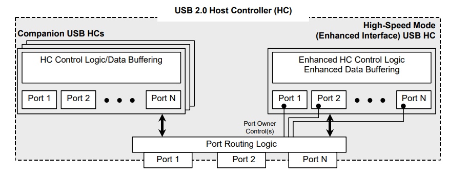
Also for the future I want to immediately warn that your driver may not work correctly because of such a ridiculous situation: you initialized the UHCI, and then the EHCI, added two identical devices, put the Port Owner Control bits in the port register, and then UHCI stopped working, because the EHCI automatically pulls the port to itself, and the port on the UHCI stops responding, this situation must be monitored.
Also, let's take a look at a diagram showing the EHCI architecture itself:
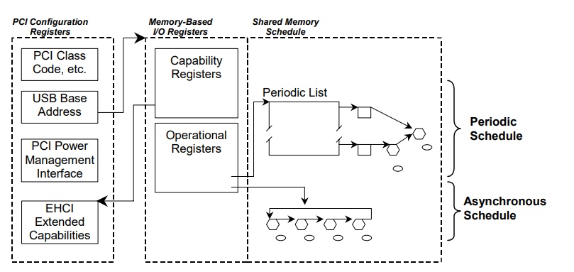
On the right is written about the queue - about them later.
EHCI controller registers
To begin with, I would like to clarify once again that through these registers you will control your device, therefore they are very important - and without them, EHCI programming is impossible.
First you need to get the address of the MMIO, which is issued to this controller, at the offset + 0x10 will be the address of our long-awaited registers. There is one thing: first, the Capability registers go, and only after them - the Operational, so at offset 0 (from the previous address, which we received at offset 0x10 relative to the start of the EMI of our EHCI MMI) there is one byte - the length of the Capability registers.
Capability registers
At offset 2, the HCIVERSION register is located - the revision number of this HC, which occupies 2 bytes and contains the BCD version of the revision (what BCD can be learned from Wikipedia).
At offset +4 lies the HCSPARAMS register, its size is 2 words, it contains the structural parameters of the device and its bits show the following:
- Bit 16 - Port Indicators - Available LEDs for connected USB devices.
- Bits 15:12 is the number of the companion controller that is assigned to this controller
- Bits 11: 8 - the number of ports in the companion controller
- Bit 7 - Port Routing Rules - shows how these ports are tied to companion ports
- Bit 4 - Port Power Control - shows whether it is necessary to turn on the power for each port, 0 - power is automatically supplied
- Bits 3: 0 - the number of ports in this controller.
- At offset +8, the HCCPARAMS register is located — it shows the compatibility parameters, its bits mean the following:
- Bit 2 - the availability of the asynchronous queue
- Bit 1 - periodic (sequential) queue availability
- Bit 0 - 64-bit compatibility
Operation registers
At offset 0, the USBCMD register is the command register of the controller, its bits mean the following:
- Bits 23:16 - Interrupt Threshold Control - shows how many micro-frames will be used per regular frame. The more, the faster, but if more than 8 - then the micro-frames will be processed with the same speed as for 8.
- Bit 6 - interrupt after each transaction in the asynchronous queue,
- Bit 5 - is the asynchronous queue used,
- Bit 4 - use sequential queue,
- Bits 3: 2 - FrameList'a size (about this - further). 0 means 1024 elements, 1 - 512, 2 - 256, 3 - reserved
- Bit 1 — Set to perform a host controller reset.
- Bit 0 - Run / Stop
Next, by offset +4, the register is USBSTS - the statute of the host controller,
- Bit 15 indicates whether an asynchronous queue is being used.
- Bit 14 indicates whether a sequential queue is being used,
- Bit 13 — Indicates an empty asynchronous queue is detected,
- Bit 12 is set to 1, if an error occurs while processing a transaction, then the host controller will stop all queues.
- Bit 4 is set to 1, if a serious error occurs, the host controller stops all queues.
- Bit 3 FrameList (Register) Rollover - set to 1 when the host controller has processed the entire frameList.
- Bit 1 - USB Error Interrupt - generate an error interrupt?
- Bit 0 - USB Interrupt - set after successful transaction processing, if IOC was set in TD
Not tired? You can pour yourself a strong tea and bring livers, we are still at the very beginning!
At offset +8 is a register USBINTR - register enable interrupts
In order not to write for a long time, and even more so, you don’t have to read for a long time, the bit values of this register can be viewed in the specification, a link to it will be left below. Here I just write down 0, because I absolutely have no desire to write handlers, interrupt interrupts, etc., so I think this is almost absolutely pointless.
At offset +12 (0x0C) lies the FRINDEX register, which simply contains the current frame number, and I want to note that the last 4 bits indicate the micro frame number, and in the older 28 bits the frame number (the value is not necessarily smaller than frameList “But if you need an index, it's better to take it with a mask of 0x3FF (or 0x1FF, etc.).
The CTRLDSSEGMENT register is at offset + 0x10, it shows the host controller the upper 32 bits of the frame sheet address.
The PERIODICLISTBASE register has an offset of + 0x14, in which you can put the lower 32 bits of the frame sheet, note that the address must be aligned to the size of the memory page (4096).
The ASYNCLISTADDR register has an offset + 0x18, in it you can put the address of the asynchronous queue, note that it must be aligned at the 32-byte boundary, while it must be in the first four gigabytes of physical memory.
The CONFIGFLAG register indicates whether the device is configured. You must set the bit 0 after the device is configured, it has an offset + 0x40.
We turn to the port registers. Each port has its own command-status register, each port register is located at + 0x44 + offset (PortNumber - 1) * 4 , its bits mean the following:
- Bit 12 - port power, 1 - power is supplied, 0 - no.
- Bit 8 - Port Rest - is set to reset the device.
- Bit 3 - Port Enable / Disable Change - is set when the port is turned on.
- Bit 2 - Port Enabled / Not Enabled.
- Bit 1 - Change the connection status, put in 1, for example, if you connected or disconnected the USB device.
- Bit 0 - connection status, 1 - connected, 0 - no.
We now turn to the juice.
Transmission and query structures
The organization structure for processing requests includes queue and transfer descriptors (TDs).
At the moment we will consider only 3 structures.
Sequential list
The consecutive (Periodic, Pereodic) list is arranged as follows:
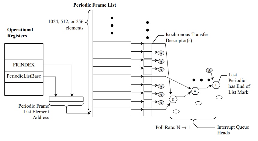
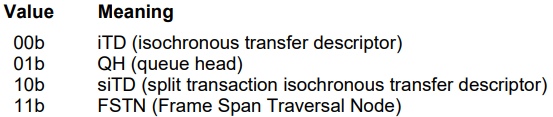
As can be seen in the diagram, processing begins with getting the required frame from the frame of the sheet, each of its elements takes 4 bytes and has the following structure:

As you can see in the picture, the queue address / descriptor transfer is aligned at 32 bytes, bit 0 means that the host controller will not process this element, bits 3: 1 indicate the type of what the host controller will handle: 0 - isosynchronous TD (iTD), 1 - turn, 2 and 3 in this article I will not consider.
Asynchronous queue
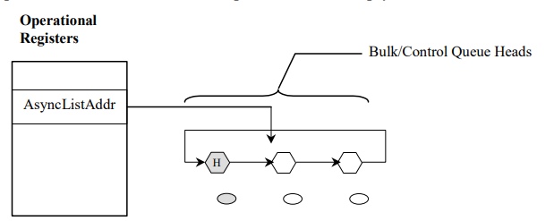
The host controller processes this queue only when the frame is consecutive empty, or the host controller has processed the entire sequential list.
An asynchronous queue is a pointer to a queue that contains other queues that need to be processed. Scheme:
qTD (Queue Element Transfer Descriptor)
This TD has the following structure:
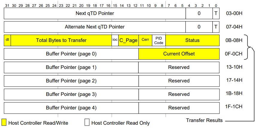
Next qTD Pointer - a pointer to the continuation of the queue for processing (for Horizontal Execution), bit 0 Next qTD Pointer shows that there is no further queue anymore.
qTD Token - TD token, shows data transfer parameters:
- Bit 31 - Data Toggle (more on that later)
- Bits 30:16 - the amount of data to transfer, after the completion of the transaction, their value is reduced by the amount of transmitted data.
- Bit 15 - IOC - Interrupt On Complete - cause an interrupt after the handle has finished processing.
- Bits 14:12 show the number of the current buffer, to which / from which data is exchanged, about this later.
- Bits 11:10 - allowable number of errors. This table shows when the error count decreases:
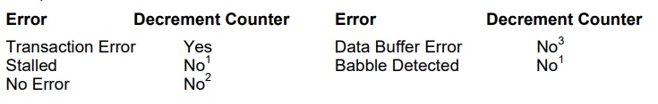
Footnote 1 - Babble or Stall detection automatically stops execution of the queue head. Footnote 3 - Data buffer errors are problems with the host. They do not take into account device retries. - 9: 8 - PID Code - token type: 0 - input token (from host to device), 1 - output token (from device to host), 2 - “SETUP” token
- Bits 7: 0 indicate TD status:
Bit 7 indicates that the TD has an active state (i.e., the host controller is processing the TD)
Bit 6 - Halted - indicates that an error has occurred and TD execution has stopped.
Bit 4 - Babble Detected - the amount of data that we sent to the device, or vice versa, is less than we transmit, that is, for example, the device sent us 100 bytes of data, and we read only 50 bytes, and then 50 more The Halted bit will also be set if this bit is set to 1.
Bit 3 - Transaction Error - an error occurred during the transaction.
qTD Buffer Page Pointer List - any of 5 buffers. Contains a link to where to make a transaction in memory (send data to the device / accept data from the device), all addresses in the buffers, except the first, should be aligned to the page size (4096 bytes).
Head queue
The Queue Head has the following structure:
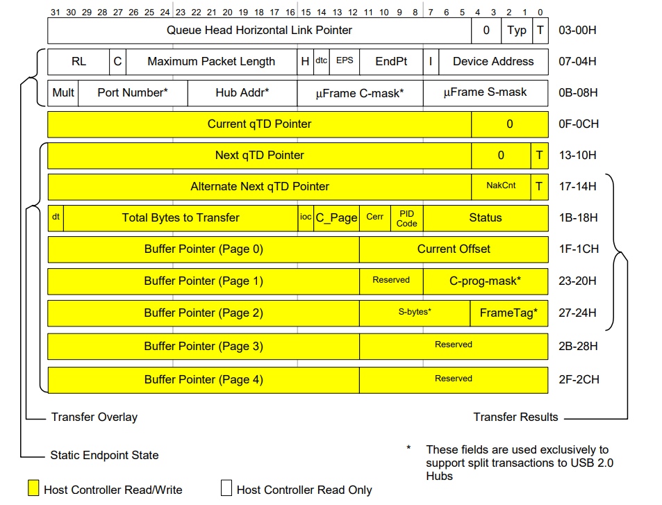
Queue Head Horizontal Link Pointer - pointer to the next queue, bits 2: 1 have the following values depending on the type of queue:
Endpoint Capabilities / Characteristics - queue characteristics:
- Bits 26:16 contain the maximum packet size for transmission
- Bit 14: Data Toggle Control - indicates where the host controller should take the initial Data Toggle value, 0 - ignores the DT bit in qTD, stores the DT bit for the head of the queue.
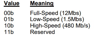
- Bit 13:12 - transmission rate characteristics:
- Bits 11: 8 - the number of the end point to which the request is made
- Bits 6: 0 - device address
Endpoint Capabilities: Queue Head DWord 2 - continuation of the previous double word:
- Bits 29:23 - Hub number
- Bits 22:16 - Address of the Hub
Current qTD Link Pointer - pointer to the current qTD.
We turn to the most interesting.
EHCI driver
To begin with, what kind of requests can EHCI perform. There are 2 types of requests: Control - a la commands, and Bulk - to the endpoints, for data exchange, for example, the absolute majority of USB flash drives (USB MassStorage) use the Bulk / Bulk / Bulk data transfer type. The mouse and keyboard for data transmission also use Bulk - requests.
We initialize EHCI and configure asynchronous and sequential queues:
// Base I/O Address PciBar bar; PciGetBar(&bar, id, 0); EhciController *hc = VMAlloc(sizeof(EhciController)); hc->capRegs = (EhciCapRegs *)(uintptr_t)bar.u.address; hc->opRegs = (EhciOpRegs *)(uintptr_t)(bar.u.address + hc->capRegs->capLength); // Read the Command register // uint cmd = ROR(usbCmdO); // Write it back, setting bit 2 (the Reset bit) // , 2(Reset) // and making sure the two schedule Enable bits are clear. // , 2 WOR(usbCmdO, 2 | cmd & ~(CMD_ASE | CMD_PSE)); // A small delay here would be good. You don't want to read // , // the register before it has a chance to actually set the bit // , ROR(usbCmdO); // Now wait for the controller to clear the reset bit. // Reset while (ROR(usbCmdO) & 2); // Again, a small delay here would be good to allow the // reset to actually become complete. // ROR(usbCmdO); // wait for the halted bit to become set // Halted while (!(ROR(usbStsO) & STS_HCHALTED)); // , // , 128 hc->frameList = (u32 *)VMAlloc(1024 * sizeof(u32) + 8192 * 4); hc->frameList = (((uint)hc->frameList) / 16384) * 16384 + 16384; hc->qhPool = (EhciQH *)VMAlloc(sizeof(EhciQH) * MAX_QH + 8192 * 4); hc->tdPool = (EhciTD *)VMAlloc(sizeof(EhciTD) * MAX_TD + 8192 * 4); hc->qhPool = (((uint)hc->qhPool) / 16384) * 16384 + 16384; hc->tdPool = (((uint)hc->tdPool) / 16384) * 16384 + 16384; // Asynchronous queue setup // EhciQH *qh = EhciAllocQH(hc); // , // , qh->qhlp = (u32)(uintptr_t)qh | PTR_QH; // , , qh->ch = QH_CH_H; qh->caps = 0; qh->curLink = 0; qh->nextLink = PTR_TERMINATE; qh->altLink = 0; qh->token = 0; // for (uint i = 0; i < 5; ++i) { qh->buffer[i] = 0; qh->extBuffer[i] = 0; } hc->asyncQH = qh; // Periodic list queue setup // qh = EhciAllocQH(hc); // qh->qhlp = PTR_TERMINATE; qh->ch = 0; qh->caps = 0; qh->curLink = 0; qh->nextLink = PTR_TERMINATE; qh->altLink = 0; qh->token = 0; // for (uint i = 0; i < 5; ++i) { qh->buffer[i] = 0; qh->extBuffer[i] = 0; } qh->transfer = 0; qh->qhLink.prev = &qh->qhLink; qh->qhLink.next = &qh->qhLink; hc->periodicQH = qh; // for (uint i = 0; i < 1024; ++i) hc->frameList[i] = PTR_QH | (u32)(uintptr_t)qh; kprintf("FrameList filled. Turning off Legacy BIOS support..."); // Check extended capabilities // BIOS Legacy support uint eecp = (RCR(hccParamsO) & HCCPARAMS_EECP_MASK) >> HCCPARAMS_EECP_SHIFT; if (eecp >= 0x40) { // Disable BIOS legacy support uint legsup = PciRead32(id, eecp + USBLEGSUP); kprintf("."); if (legsup & USBLEGSUP_HC_BIOS) { PciWrite32(id, eecp + USBLEGSUP, legsup | USBLEGSUP_HC_OS); kprintf("."); for (;;) { legsup = PciRead32(id, eecp + USBLEGSUP); kprintf("."); if (~legsup & USBLEGSUP_HC_BIOS && legsup & USBLEGSUP_HC_OS) { break; } } } } kprintf("Done\n"); // Disable interrupts // //hc->opRegs->usbIntr = 0; MWIR(ehcibase, usbIntrO, 0); // Setup frame list // //hc->opRegs->frameIndex = 0; WOR(frameIndexO, 0); //hc->opRegs->periodicListBase = (u32)(uintptr_t)hc->frameList; WOR(periodicListBaseO, (u32)(uintptr_t)hc->frameList); // //hc->opRegs->asyncListAddr = (u32)(uintptr_t)hc->asyncQH; WOR(asyncListAddrO, (u32)(uintptr_t)hc->asyncQH); // 0 //hc->opRegs->ctrlDsSegment = 0; WOR(ctrlDsSegmentO, 0); // Clear status // //hc->opRegs->usbSts = ~0; WOR(usbStsO, ~0); // Enable controller // , 8 -, // //hc->opRegs->usbCmd = (8 << CMD_ITC_SHIFT) | CMD_PSE | CMD_ASE | CMD_RS; WOR(usbCmdO, (8 << CMD_ITC_SHIFT) | CMD_PSE | CMD_ASE | CMD_RS); while (ROR(usbStsO)&STS_HCHALTED); // Configure all devices to be managed by the EHCI // , //hc->opRegs->configFlag = 1; WOR(configFlagO, 1);\ // Probe devices // EhciProbe(hc); Actually, the code to reset the port to its original state:
volatile u32 *reg = &hc->opRegs->ports[port]; // , 100 *reg|=(1<<12)|(1<<20); Wait(100); // , 50 EhciPortSet(reg, PORT_RESET | (1<<12) | (1<<20) | (1<<6)); Wait(50); EhciPortClr(reg, PORT_RESET); // Wait 100ms for port to enable (TODO - what is appropriate length of time?) // 100 , , // 100 uint status = 0; for (uint i = 0; i < 10; ++i) { // Delay Wait(10); // Get current status // status = *reg; // Check if device is attached to port // if (~status & PORT_CONNECTION) break; // Acknowledge change in status // - if (status & (PORT_ENABLE_CHANGE | PORT_CONNECTION_CHANGE)) { EhciPortClr(reg, PORT_ENABLE_CHANGE | PORT_CONNECTION_CHANGE); continue; } // Check if device is enabled // , if (status & PORT_ENABLE) break; } return status; Control request to the device:
static void EhciDevControl(UsbDevice *dev, UsbTransfer *t) { EhciController *hc = (EhciController *)dev->hc; UsbDevReq *req = t->req; // Determine transfer properties // uint speed = dev->speed; uint addr = dev->addr; uint maxSize = dev->maxPacketSize; uint type = req->type; uint len = req->len; // Create queue of transfer descriptors // TDs EhciTD *td = EhciAllocTD(hc); if (!td) return; EhciTD *head = td; EhciTD *prev = 0; // Setup packet // uint toggle = 0; uint packetType = USB_PACKET_SETUP; uint packetSize = sizeof(UsbDevReq); EhciInitTD(td, prev, toggle, packetType, packetSize, req); prev = td; // Data in/out packets packetType = type & RT_DEV_TO_HOST ? USB_PACKET_IN : USB_PACKET_OUT; u8 *it = (u8 *)t->data; u8 *end = it + len; //EhciPrintTD(td); while (it < end) { td = EhciAllocTD(hc); if (!td) return; toggle ^= 1; packetSize = end - it; if (packetSize > maxSize) packetSize = maxSize; EhciInitTD(td, prev, toggle, packetType, packetSize, it); it += packetSize; prev = td; } // Status packet // td = EhciAllocTD(hc); if (!td) return; toggle = 1; packetType = type & RT_DEV_TO_HOST ? USB_PACKET_OUT : USB_PACKET_IN; EhciInitTD(td, prev, toggle, packetType, 0, 0); // Initialize queue head // : EhciQH *qh = EhciAllocQH(hc); EhciInitQH(qh, t, head, dev->parent, false, speed, addr, 0, maxSize); // Wait until queue has been processed // EhciInsertAsyncQH(hc->asyncQH, qh); EhciWaitForQH(hc, qh); } Queue processing code:
if (qh->token & TD_TOK_HALTED) { t->success = false; t->complete = true; } else if (qh->nextLink & PTR_TERMINATE) if (~qh->token & TD_TOK_ACTIVE) { if (qh->token & TD_TOK_DATABUFFER) kprintf(" Data Buffer Error\n"); if (qh->token & TD_TOK_BABBLE) kprintf(" Babble Detected\n"); if (qh->token & TD_TOK_XACT) kprintf(" Transaction Error\n"); if (qh->token & TD_TOK_MMF) kprintf(" Missed Micro-Frame\n"); t->success = true; t->complete = true; } if (t->complete) .... And now the request to the end point (Bulk-request)
static void EhciDevIntr(UsbDevice *dev, UsbTransfer *t) { EhciController *hc = (EhciController *)dev->hc; // Determine transfer properties // uint speed = dev->speed; uint addr = dev->addr; uint maxSize = t->endp->desc->maxPacketSize; uint endp = t->endp->desc->addr & 0xf; EhciTD *td = EhciAllocTD(hc); if (!td) { t->success = false; t->complete = true; return; } EhciTD *head = td; EhciTD *prev = 0; // Data in/out packets uint toggle = t->endp->toggle; uint packetType = t->endp->desc->addr & 0x80 ? USB_PACKET_IN : USB_PACKET_OUT; uint packetSize = t->len; EhciInitTD(td, prev, toggle, packetType, packetSize, t->data); // Initialize queue head // EhciQH *qh = EhciAllocQH(hc); EhciInitQH(qh, t, head, dev->parent, true, speed, addr, endp, maxSize); //printQh(qh); // Schedule queue // EhciInsertPeriodicQH(hc->periodicQH, qh); } I think that the topic is quite interesting, there are almost no documents, descriptions and articles on this topic on the Internet, and if there is, it is very vague. If you are interested in the topic of working with hardware and OS development, then there is a lot to say.
Docks: Specification
Source: https://habr.com/ru/post/426421/
All Articles