Arduino. Project "Robot Machine RoboCar4W"
You understand, ”the editor explained,“ it must be entertaining, fresh, full of interesting adventures ... So that the reader could not tear himself away.
I. Ilf, E. Petrov "How Robinson was created" .
Getting started with Arduino, as with any other software or hardware platform, is always more interesting from a real project. The programmers at the same time write the code outputting “Hello, world”, arduinists blink the LED. And everyone is happy as children.
I decided to start with an advanced project, including with the secret hope of tearing the younger generation from Counter-Strike (it did not work).
As you can guess from the name of RoboCar4W, the first project was a four-wheel robot machine. Starting work, I already had programming experience, I was once able to solder, but I didn’t even know the Arduino pinouts and didn’t read the documentation at all. All the wisdom studied in the course of the play and Google to help.
Since the project itself is not fundamentally new, such descriptions on the network are sufficient, all components are known, no surprises were assumed. Therefore, the idea was formulated in the most general terms and the main goal was to dive into the “world of things” with the help of Arduino, as a platform for rapid prototyping. In this opus, someone might recognize themselves at the very beginning of the journey.
All the "hardware" was purchased on ebay, and from my own experience I want to say that it is easier to purchase a starter kit right away (look according to the Arduino Starter Kit) and not to collect it in detail. Yes, and all come together. It was decided not to waste time on trifles, to buy a normal chassis, normal wheels, normal engines, so it was "expensive".
The main secret of successful purchases on eBay is to buy from sellers with a high rating and at the same time carefully read the product description. There are many articles on the Internet about this.
What is the Arduino family charge?
I took Arduino UNO, under it many projects with descriptions. But now I would take the Arduino Mega 2560, it has more digital and analogue outputs and full compatibility with UNO on projects.
General description of the project
In the world of software development, this is also called “system requirements”.
The idea of the project was as follows. The first version of the robot machine called RoboCar4W should perform simple actions:
- move forward
- measure the distance to the obstacles
- be able to automatically go around obstacles in front.
The second version of the machine must be controlled manually via bluetooth from an Android phone.
To make you work better here, the entire final project of RoboCar4W in the collection (here without bluetooth).

Here is a video of running trials.
In the first video, RoboCar4W rides automatically with a detour of obstacles on two different versions of the “firmware”, i.e. the sketch, therefore, if someone is the most keen and noticed that the behavior of the robot in different episodes is slightly different.
In the second video, RoboCar4W moves using commands transmitted by the “driver” via Bluetooth from an Android mobile phone. The phone has Bluetooth RC Car installed. Moreover, if an obstacle is close ahead, the robot stops, i.e. ram something does not work (but there is a "secret" button that disables safe mode).
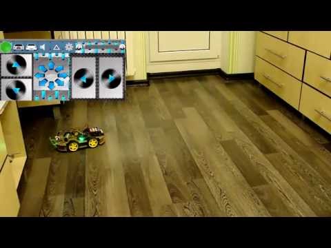
In the third video, RoboCar4W shows a pre-programmed motion demo program with turns. The demo program is activated by a team from the same mobile phone for Android. The robot just rides for a while and makes turns.
Motion control algorithm
It is a mistake to call our way “the algorithm of avoiding obstacles” or “searching for a path”. These are separate mathematical disciplines, pure mathematics. If you like mathematics very, very much, then google these phrases, you will be provided with reading material for half a year.
In the meantime, we are interested in things much easier. Therefore, we call it simple - the algorithm for controlling the movement of a 4-wheeled robot. Of course we are talking about automatic control without human intervention.
Here is a simple algorithm written in words, for more complex algorithms you have to (like or not) make up flowcharts.
Now simultaneously look at the source of the sketch RoboCar4W-1.ino .
- We measure the distance to the obstacle ahead.
- If this measured distance is less than the value of
DST_TRH_BACK(shortened from the distance threshold), then we stop and drive backwards at the same time turning. The direction of rotation is chosen as follows: if you have previously turned left, then turn right and vice versa. - If the measured distance is greater than
DST_TRH_BACK, but less thanDST_TRH_TURN, then simply rotate. The direction of rotation is chosen randomly. - If the obstacle is far away, then just go ahead.
- Repeat all over again.
What is good that we have 4 wheels and all the leading? We can perform (program) several types of turns:
- Smooth turn. All wheels rotate, but the wheels on the one hand rotate faster.
- Sharp turn. Wheels rotate on one side only.
- Turn on the spot. Like a tractor, the wheels of one side rotate back and the other - forward.
In the second version of the program, when operating from an Android phone, safe mode, when the robot tries to prevent frontal collisions, can be disabled if the program presses the button twice
and turned it back on by pressing it once.
Important note . All logic is controlled by Arduino. Android here simply acts as a gaming console (without brains) from the console, its task is to stupidly transmit button presses (i.e. commands) via Bluetooth to the Arduino RoboCar4W.
Components
Initially, the machine included a servo drive, which turned the ultrasonic distance meter at a certain angle for measurements in three directions. But during the tests, due to careless handling, the servo burned down, so now the distance sensor is simply rigidly fixed in front of the case.
A blessing in disguise, but the sketch has become a little easier.
For the future, buy the servo the simplest and cheapest, special power, speed and accuracy of turning at a given angle are not needed, and it is quite easy to turn the servo out of order, as it turned out. A SG90 worth $ 2 is fine.
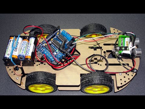
So the components of the project RoboCar4W, the description in English is given to facilitate the search on ebay and others like it:
- Arduino UNO R3
- Ready Chassis 4 Wheel Drive Mobile Robot Platform Smart Car Chassis Arduino Compatible
- DC motors (DC) with rotation in both directions - 4 pcs.
- Wheels - 4 pcs.
- Board to control 4 DC Motor Drive Shield L293D motors
- Ultrasonic Distance Meter HC-SR04 Ultrasonic Module Distance Measuring Sensor
- Ni-MH 1.2 V batteries - 8 pcs.
- Plastic box holder for batteries; Battery Box holder 4 AA Batteries - 2 pcs.
- Battery type "Krona" 8.4 V - 1 pc.
- Optional toggle switch - power switch
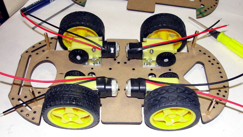
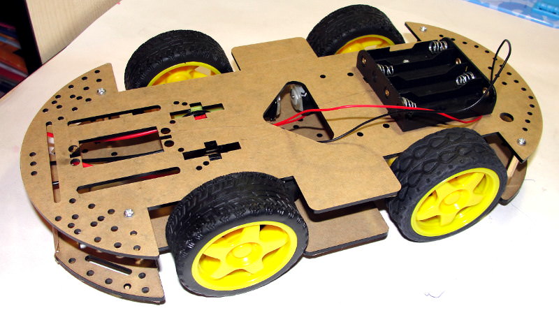
Chassis, DC motors and wheels were purchased immediately in the kit and even with assembly instructions.
Pinout
Analog inputs can be used as digital I / O port pins. Arduino pins, corresponding to analog inputs, have numbers from 14 to 19. This applies only to Arduino pins, and not to the physical pin numbers of the Atmega microcontroller.
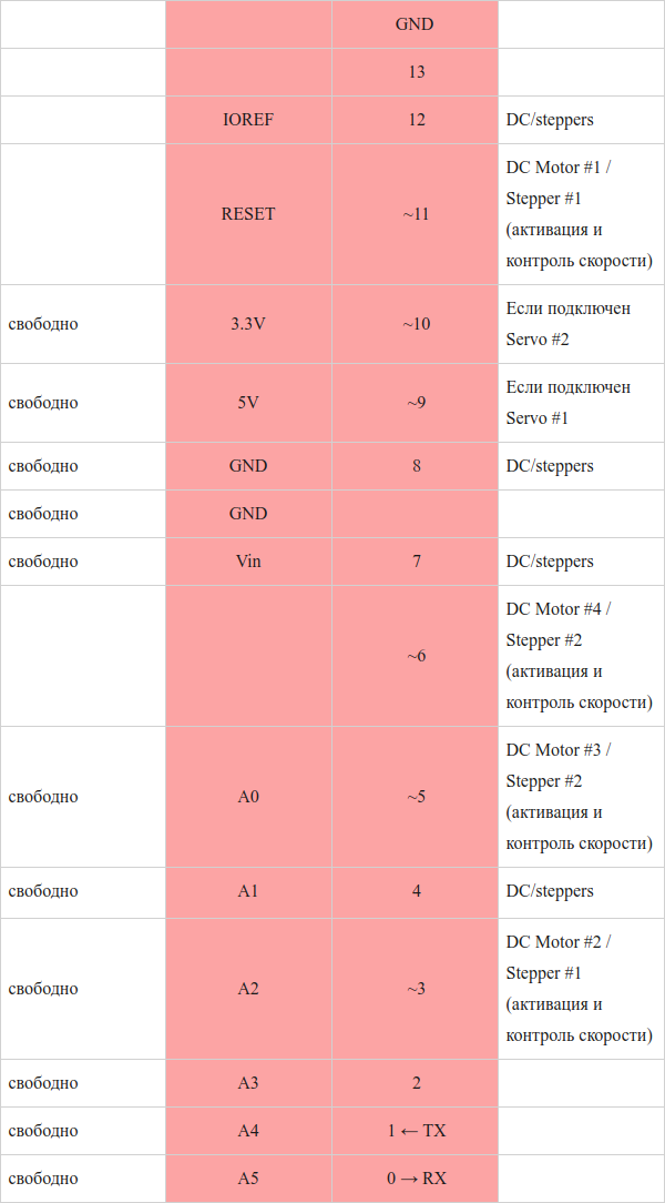
It is not necessary to draw, you can simply reduce everything to a table. I did it like this.
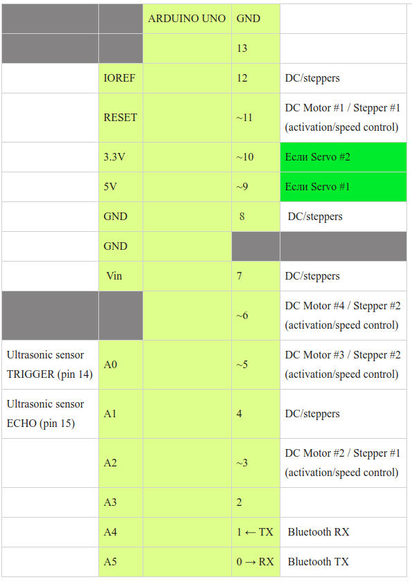
Pins D4, D7, D8, D12 will be occupied if any DC or step motors are used.
Pins D9 (Servo # 1 control), D10 (Servo # 2 control) will be occupied only if servos are used.
By itself, the board for controlling the Motor Drive Shield L293D motors is not occupied by Arduino pins.
The power supply pins 3.3 V, 5 V and “ground” are duplicated on the Motor Drive Shield in sufficient quantities. Therefore, there is no need to worry about their shortage.
If you still want to paint beautifully, then the free Fritzing program will help you.
Nutrition
This is the second very important point. A lot depends on nutrition. For example, a servo-motor starts to consume a large current when the shaft turns through a given angle. Moreover, if the servo is connected to the 5 V power supply of the Arduino, then the voltage drops and the rest of the circuit starts to fail, and the Arduino can even reboot at the same time.
In any case, if you use motors in an odd job, the Motor Drive Shield is necessary (or a similar scheme).
So, we have 4 DC motors (DC), a servo drive, the Arduino board itself, and several sensors. The motors are the most voracious, but the sensors can be successfully powered from the connectors of the Arduino board itself, so everything is simple with them. For convenience, I brought the whole economy in one table.
| Recommended or typical voltage. Current consumption | Max voltage | What is planned to feed | Notes | |
|---|---|---|---|---|
| Arduino UNO R3 board | 7 - 12V, 200mA (average) | 6 - 20 | “Krone 9V” Li-ion 650mAh, 8.4V | Connector with a plus in the center |
| Servo motor MG-995 | 5-6 V, 0.1 - 0.3A (peak) | 4.8 - 7.2 | Batteries (5) pcs. Ni-Mh 1.2V = 6V | Food only from a separate source. If powered with Arduino, everything will be buggy. Ni-Mh battery voltage 4pcs. * 1.2V = 4.8V is not enough. Some argue that this servo should not be used on 6 volts, only 4.8 |
| DC motors (4 pcs.) | 6 - 8V, current from 70mA to 250mA | 3 - 12 | batteries (5 + 3) pcs. Ni-Mh 1.2V = 9.6V | You will not be able to start the engines from a 9V battery, so do not even waste time (and batteries)! |
| Motor Drive Shield L293D | not required | 4.5 - 36 | not required | |
| Bluetooth module HC-0506 | 3.3 V, 50 mA | 1.8–3.6 | From pin 3.3V Arduino board | |
| Ultrasonic distance meter HC-SR04 | 5 V, 2 mA | five | With pin 5V Arduino board |
I did not have a DC / DC voltage converter. Krone 9V was not a very good power source, I just had it already.
But I refused to use high-capacity Li-ion batteries. First, because of the high cost, and secondly, in Chinese online shops it is easy to run into a fake. More precisely, not "easy", but "always." In addition, Li-ion requires special handling, and it is not safe.
So, as we see from the table, we need 3 independent power sources:
- For Arduino board and sensors.
- For servomotor.
- For 4 DC motors.
Where is so much to dial? The Arduino board itself, in any case, must be powered from a separate source, since when the voltage drops, for example, from switching on the motors, the board can reboot or simply fail. Here we use the battery of the “Kron 9V” form factor, and the connector that will be connected to the Arduino should be with a “plus in the center”.
For servomotor and 4-DC motors, you can do with one power source. The only problem is that the servomotor is designed for a voltage of 5-6V (maximum 7.2V) and a current of 100-300mA (peak), and DC motors require 6-8V (maximum 12V) and a current of 250mA.
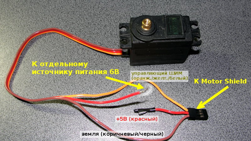
To solve the problem, there are DC-DC converters, but I did not have such. As a result, I applied my “proprietary” connection scheme (without any downward electronic circuits, only environmentally friendly voltage and current!): I connected 8 pcs. 1.2V batteries in series and made taps in the right places, as shown in the diagram.
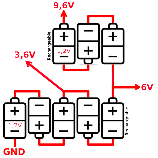
6B went to the servomotor, and 9.6 to DC motors. It is clear that the batteries 1--5 will experience increased load.
To control the servo and DC motors, I used a 4-channel Motor Drive Shield based on the L293D chip.
Assembly
Assembling the finished chassis is a small problem. But do not think that without finishing, everything will come together at once. Therefore, prepare the files.
Connect normally several motors, servomotor or stepper directly to the Arduino will not succeed. Since the pins (conclusions) Arduino are weak. To solve the problem, there is an additional drive control module - Motor Drive Shield based on the L293D chip, which is one of the most common chips designed for this purpose. The L293D chip is also known as the H-Bridge.
I used a board that provides 4 channels for connecting on two L293D chips and a shift register. Purchased on eBay for $ 5.
This drive control module board has the following characteristics.
- L293D Motor Drive Shield compatible with Arduino Mega 1280 and 2560, UNO, Duemilanove, Diecimila
- 4 channel control
- motor power from 4.5V to 36V
- permissible load current 600 mA per channel, peak current - 1.2A
- overheat protection
- 2 interfaces with a precise Arduino timer (there will be no “jitter”) for connecting servomotors to a voltage of 5V, if the supply voltage needs to be higher, then the power connection needs to be redone as described below
- 4 bi-directional DC collector motors or 2 stepper and 2 servomotors can be controlled simultaneously
- 4 bi-directional DC motors each connected to an 8-bit bus to select individual speeds.
- connection up to 2 stepper drives (unipolar or bipolar), with one coil, double coil or alternating pitch
- connector for connecting an external source for separate supply of control logic and motors
- RESET Arduino button
- Adafruit AFMotor library is used for management.
Motor Drive Shield requires a little work in order to be able to connect anything after it. I soldered on top of the necessary connectors, it turned out that's what.

Motors can be connected to an additional power supply with respect to the Arduino board. I recommend this type of connection. To do this, remove, open the jumper, as shown in the picture.
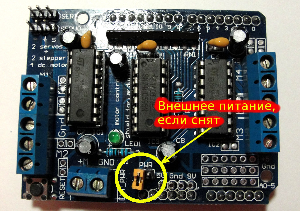
In this case, the Arduino is powered and the motors are powered independently of each other.
The LED on the motor-shield glows when there is power to the motors; if it is off, the motors will not work.
New problem.
The servo position of the power jumper does not apply, they will still be powered by 5V Arduino. Since servomotors usually consume a large current and if there is not enough power, the whole device starts to fail, in the "best" case only the servo will fail - it will not turn at a given angle, or all the time before each turn, turn first to 0 degrees and then at a given angle (and if you have time). Therefore, I recommend powering the servo also from an additional power source. To do this, you will have to alter the connection scheme a bit: bite off the positive wire (usually red) from the standard connector and connect it directly to the power source.
When connecting Motor Drive Shield analog pins are not used. Digital pins 2, 13 are not used.
The following pins are used only if the corresponding DC motors or stepper motors (Stepper) are connected and used:
- D11: DC Motor # 1 / Stepper # 1 (activation and speed control)
- D3: DC Motor # 2 / Stepper # 1 (activation and speed control)
- D5: DC Motor # 3 / Stepper # 2 (activation and speed control)
- D6: DC Motor # 4 / Stepper # 2 (activation and speed control)
These pins will be occupied if any DC / steppers are used: D4, D7, D8, D12.
The following pins will be occupied only if the corresponding servomotors are used:
- D9: Servo # 1 control
- D10: Servo # 2 control
To get started with Motor Drive Shield, you need to download and install the Adafruit AFMotor library.
Sample code for controlling motors:
#include <AFMotor.h> // Adafruit #include <Servo.h> // AF_DCMotor motor(1); // , DC Motor Shiled , , frequency Servo servo; // servo.attach(10); // 9 10 ( Motor Shiled) motor.setSpeed(speed); // DC 0 () 255 ( ) motor.run(RELEASE); // DC motor.run(FORWARD); // DC motor.run(BACKWARD); // DC servo.write(90); // 90 . DC motor I started to spin only when specifying a speed greater than 100, if less - just buzzing. The minimum speed of your engine you have to determine experimentally.
For motors connected to M1 and M2, you can set the frequency: MOTOR12_64KHZ, MOTOR12_8KHZ, MOTOR12_2KHZ, MOTOR12_1KHZ. The highest speed is achieved at 64KHz, this frequency will be audible, a lower frequency and speed at 1KHz but also uses less energy. Motors 3 and 4 always run at 1KHz. Other values are ignored. The default is 1KHz everywhere.
After that, you need to drive test motors. Sketch for testing can be found here . At the beginning of the sketch, change the motor number in the line (or lines) of the type:
AF_DCMotor motor(…); The sketch rotates the motor (s) for some time in the direction of movement of the robot, and then back. Look carefully at whether the motor rotates and change the polarity of the connection if necessary.
We connect the ultrasonic distance meter HC-SR04 Ultrasonic Module. Pinout pinouts:
- Vcc
- Trig (T)
- Echo (r)
- GND
The time spent by the ultrasonic rangefinder on the measurement (determined empirically):
- maximum 240 msec if the distance is too large (out of range)
- at least 1 ms, if the distance is too short
- a distance of 1.5 m is determined in approximately 10 ms

Ultrasonic sensor rangefinder, because of its physical nature, and not because China, in some cases, poorly determines the distance to the obstacle:
- if the obstacle is of a complex shape, then the ultrasound is reflected at different angles and the sensor is mistaken,
- Ultrasound is perfectly absorbed (i.e. not reflected) by soft furniture or toys, and the sensor considers that there is nothing in front of it.
In other words, for an ultrasonic range finder, ideally, it would be great if all the obstacles were in the form of a solid plane perpendicular to the direction of radiation of ultrasound.
Some problems can be solved with an infrared distance sensor. But he is also not perfect:
- small maximum range in comparison with ultrasonic: 0.3—0.8 m versus 4 m
- big minimum distance in comparison with ultrasonic: 10 cm against 2 cm
- the dependence of the sensitivity of the sensor from the total illumination.
Although if you set these rangefinders in a pair, then their performance would noticeably increase.
Connect Bluetooth HC-05
As you can see from the datasheet the main pins of the “bare” HC-05:
- TX (pin 1) transmission
- RX (pin 2) reception
- 3.3V (pin 12) 3.3V power supply
- GND (pin 13) land
- PIO8 (pin 31) mode indicator
- PIO9 (pin 32) connection status, if the connection is established, the output will be high
- PIO11 (pin 34) to enable AT command mode
Our module is soldered to the Breakout / Base Board, where there is already a voltage divider, so its operating voltage range is from 3.3V to 6V.
We connect our complete Bluetooth module:
- Arduino (TX) - (RX) HC-05
- Arduino (RX) - (TX) HC-05
- Arduino (+ 5V) - (VCC) Bluetooth
- Arduino (GND) - (GND) Bluetooth
- pins LED, KEY are not used
After energizing the Bluetooth HC-05 module, the LED should blink on it, which means that the bluetooth is working.
Turn on bluetooth on the mobile, find the device with the name HC-05 and connect, password 1234.
To test, fill in Arduino with a simple sketch:
int count = 0; void setup() { Serial.begin(9600); Serial.println("Test Arduino + Bluetooth. http://localhost"); } void loop() { count++; Serial.print("Count = "); Serial.println(count); delay(1000); } On Android phone, install Bluetooth Terminal. Connect to the HC-05 device and watch the creeping lines on the phone screen with an increasing counter.
To enable the module to receive AT commands, you need to transfer it to the appropriate mode — to do this, set the KEY (PIO11) pin to logical 1. On some Breakout / Base Board, instead of the KEY pin, there is an EN (ENABLE) pin, which may or may not be soldered to the conclusion on the chip itself. This only applies to HC05 chips. That's just my conclusion EN board is not soldered anywhere. Therefore, it can be soldered with a separate wire to the KEY (PIO11) output of the chip. Or, during operation, to transfer the HC05 to the AT command mode, short the KEY (PIO11) chip output to the Vcc power output for a couple of seconds. For HC06, KEY is not needed.
Software
Note. Each time before loading the program in Arduino, make sure that the Bluetooth module is not connected to the Arduino. This will cause problems casting the sketch. Simply disconnect the power from the Bluetooth module or wire connecting the Arduino and RX, TX module pins.
At the beginning of the sketch, change the numbers of the motors in the lines of the type:
AF_DCMotor motor(…); Sketch for automatic mode with a detour of obstacles download here .
If you replace the string
byte debug = 0; on
byte debug = 10; This will enable debug mode.
In the debug mode, the robot RoboCar4W will not actually drive or turn the wheels. Instead, activate the serial monitor and see how it “drives” virtually. Instead of a real drive forward, the line “Forward” will be written to the serial port monitor, instead of the backward turn to the left - “Turn Back L (eft)”, etc. The ultrasonic distance measurement sensor also does nothing; instead, the distances to the obstacles are generated programmatically and randomly.
This debugging mode is convenient if you change the algorithm of the movement and instead of catching the typewriter around the room, just check everything on a “idle” move.
Sketch for manual control on bluetooth download here . The sketch has no debug mode, since everything is transparent there. You press the button - the robot goes.
Program for Adnroid Bluetooth RC Car .
Well that's all! Happy road!

')
Source: https://habr.com/ru/post/426097/
All Articles