Weather Station on Arduino from A to Z. Part 5
Ending. The previous part .
Table of contents:
- Part 1. Requirements. The choice of iron. General scheme
- Part 2. Software. Central unit, iron
- Part 3. Central unit, software
- Part 4. Transom Sensor
- Part 5. MySQL, PHP, WWW, Android
Window sensor. Software
Let's talk about the software behind the window sensor. After that you will have a complete system with which you can already experiment.
Let me remind you that the server is a central, home unit that can communicate with the Internet via WiFi, and the client is a remote, out-of-window sensor that transmits data to the server via radio.
The source code for both server and client is here .
Source texts are provided with detailed comments.
Almost nothing needs to be configured on the client.
The radio transmitter nRF24L01 +, or rather the RadioHead library, requires specifying the server and client addresses. Addresses are provided in case you have more than one server and client. An address is just any integer. When a client sends a packet with data to the server, it indicates for which server the packet is intended. The server, knowing its own address, in turn, determines whether this packet is intended for it.
Therefore, SERVER_ADDRESS on the server and on the client must match, but the CLIENT_ADDRESS for different clients must be different. In other words, if in the future you connect another new sensor to our system, then CLIENT_ADDRESS will need to be changed for it.
// #define SERVER_ADDRESS 10 #define CLIENT_ADDRESS 20 // !!! Radio number RF_CHANNEL should be the same for all. The default is 2. I changed the default number, you can choose any other.
// . #define RF_CHANNEL 73 The settings of the voltmeter to measure the battery supply voltage must be changed:
// , const float r1 = 100400; // 100K const float r2 = 9960; // 10K // // http://localhost/arduino-secret-true-voltmeter/ const float typVbg = 1.082; // 1.0 -- 1.2 To save energy, the Lightweight low power library for Arduino is used .
Here are my measurements of actual consumption for the Arduino Pro Mini with this one:
- usually 25mA
- when working with DHT the same
- with radio transmission 38 mA
- with LowPower.idle 15 mA
- with LowPower.powerDown 7.5 mA
The client makes measurements of temperature, humidity and voltage, packs it all into a data structure, sends data to the server and “falls asleep”. If there were errors during the transfer, then the transfer is immediately repeated.
The server (central, home unit), in turn, receives data, acknowledges receipt and processes it.
Database, MySQL, PHP, WWW-server
After the work done, we have a fully functional construction of the weather station. But now such meteorological stations are a dime a dozen, local crafts, this is no longer fashionable. We have the internet of things.
Therefore, let's talk about how to access these your Internet sites, attach to our weather station a database and a web-face to it.
Task setting for "webcam":
- receive and store weather station data: temperature, humidity, atmospheric pressure, supply voltage
- display this data
- build graphics.
In this case, we need a hosting with support for Apache, PHP and MySQL with the module mysqli. And these conditions are satisfied by almost any hosting on planet Earth. Or, instead of hosting, your computer will play the role of a server, connected to a home network router and having Internet access.
Database creation
Let's start from the very beginning, namely from designing and creating a database.
The database is your world and you can study it for a long time, so we will only briefly touch on those things that are directly necessary for us.
All SQL scripts are in the weather-station/server/php-sql/ directory
Where does the design of the database begin? With a logical and physical representation.
Logical representation or database schema:
- table with DHT data of temperature and humidity sensor
- table with BMP data of pressure and temperature sensor
- The specified tables do not have connections among themselves, more precisely, connections are not needed.
The physical scheme is based on a specific DBMS and data types. Easier to sort on a specific example. The SQL script make_tables.sql reveals the logical and physical schemes.
Each table should have a type field
id INTEGER UNSIGNED NOT NULL AUTO_INCREMENT The field name may differ in different databases, but the meaning is the same - it is a unique identifier, a record key. For the future, if you see a database in the tables of which there is no such counter, you should know that this database was designed by a person who is very far from programming, most likely a humanist.
Data from the same type of sensors is stored in one table, for sensors of another type we create another table. This slightly complicates the database and PHP binding to it, but it simplifies the expansion or modification of the entire system in the future.
Our project has two tables. The arduino_dht table stores data from the DHT type sensor (s) (temperature, humidity), and the data from the BMP type sensor (temperature, pressure) is stored in the arduino_bmp table. If you want to have, for example, a gas sensor or a motion detector in the future, then create additional tables, do not be lazy. If you connect another sensor like DHT11 or DHT22, then you do not need to create an additional table, use the table arduino_dht . I hope the principle is clear: a separate physical entity - a separate table.
If data from several sensors of the same type are stored in the table, how can they be distinguished? For this, a field is entered in each table.
idSensor INTEGER In fact, this is the CLIENT_ADDRESS that we CLIENT_ADDRESS in the client/client.ino for each instance of the remote client sensor and in server/server.ino for the sensor that is connected directly to the server - the central unit.
In industrial systems, there must be another table — the correspondences of idSensor and its verbal, human-readable description. For example, a sensor with idSensor = 2 is “Temperature, humidity in the apartment” , etc. But in our project we will not complicate, just remember that:
- the sensor with
idSensor, it isCLIENT_ADDRESS, equal to 11 - this is the home sensor on the server - the central unit, - The sensor with
idSensor, alsoCLIENT_ADDRESSasCLIENT_ADDRESS, equal to 20 is the first (in our project and the only) remote sensor client.
Further. The following data is stored in the tables:
- ipRemote - the IP address of the weather station (server) from which the data came from, useful for debugging and monitoring,
- dateCreate - the date the record was created,
- millis - useful for debugging, this time in milliseconds since the start of the sketch on the Arduino,
- temperature - temperature
- humidity - humidity
- voltage - supply voltage
- pressure - pressure
- errors - the number of errors (not used). Conceived to store the number of errors during transmission, etc., so that you can remotely assess the state of the entire system.
As you can see the tables arduino_dht and arduino_bmp very similar, the only difference is in the fields of pressure and humidity, and there is a desire to dump everything in one pile (table). But the first normal form does not allow it to do so, a lot of novice programmers tried to get around it, but none of them succeeded, and we will not. This is how not to notice the law of the world, for the time being it may well turn out.
The arduino_error_log table arduino_error_log useful when debugging - this is a log of errors and other system messages.
Creating a database and its user with the rights described in make_db.sql
-- . config.php -- CREATE DATABASE IF NOT EXISTS db_weather; -- CREATE USER 'u_weather'@'localhost' IDENTIFIED BY '***PASSWORD***'; GRANT ALL ON db_weather.* TO 'u_weather'@'localhost'; This is done once, the database name and user name can come up with your own. And what exactly needs to be done is to set your password.
PHP and web server
All web interface settings are stored in config.php . Modify it according to your database settings.
Set your time zone in PHP format
date_default_timezone_set('Europe/Prague'); All available time zones are described here .
Set your secret key for access (as a number) which must match the SOURCE_KEY constant from the SOURCE_KEY sketch
$access_key = '***KEY***'; In our web server there is no authorization, login by password, this would complicate the whole structure. For the prototype, this is not necessary. Therefore, all protection is based on the robots.txt file, the absence of index.php and this secret key for access.
The main PHP script, weather.php accepts a simple HTTP GET request with data and stores it in the appropriate database tables. If the $access_key key $access_key not match, then the request will be rejected.
The weather-view.php used to view data tables and contains hyperlinks to other web interface scripts. Call him like this
http:// / /weather-view.php?k= access_key for example
http://yourhost/iot/weather-view.php?k=12345 weather-view.php displays simple weather-view.php where you need to remember that:
- The sensor with id 11 is the home sensor on the server,
- The sensor with id 20 is an outside sensor.
The function.php script contains functions common to all PHP scripts.
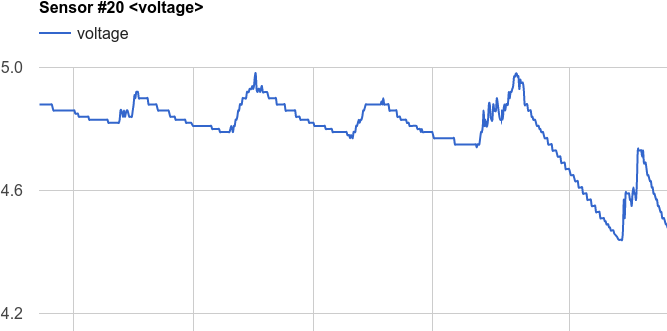
The script chart-dht.php is responsible for drawing charts using Google Charts . Here, for example, is a graph of the power supply voltage of an out-of-window sensor. The voltage rises on a sunny day at the expense of the solar battery and then the power supply on batteries gradually discharges.
export-dht.php exports data from MySQL database tables to a CSV file. For further import and analysis in spreadsheets.
export-voltage.php exports the power supply voltage of the window sensor from the MySQL database to a CSV file. Useful for debugging.
truncate.php clears all tables, i.e. deletes all our data. Useful for debugging. There are no references to this script from weather-view.php , so you need to call it via a direct link in the address bar of the browser indicating $access_key .
When receiving data, the mysqli_real_escape_string() function is commonly used to prevent incorrect values from getting into the database.
Do not forget to put a robots.txt in the root of your site to prevent it from entering the search engines.
ESP8266, WiFi and data transfer
And now we return to the server.ino sketch, to the part that connects to the WiFi access point and sends the data to the web server.
As I already wrote, I could not find a normal library for Arduino to control the ESP8266 module using AT commands, I had to “collective farm” myself. Let me remind you also that you will have to flash the firmware of a certain version in ESP8266-01. And now that everything is ready, let us analyze how it works.
To access the web server in a server.ino sketch, server.ino need to change these constants.
const String DEST_HOST = " "; // habr.com const String DEST_PORT = " "; // 80 const String DEST_URL = "/ /weather.php"; const String SOURCE_KEY= " "; // $access_key config.php In server.ino in the void setup() function, the ESP8266 is first switched to Station mode, i.e. he starts working as a wifi client
espSendCmd(«AT+CWMODE_CUR=1», «OK», 3000); and then follows the connection to the access point
espState = espConnectToWiFi(); If the connection does not occur, the attempt is repeated (once)
if ( espState != ESP_SUCCESS ) { delay(5000); Serial.println("WiFi not connected! Try again ..."); espConnectToWiFi(); } Then select a single TCP / IP connection mode.
espSendCmd("AT+CIPMUX=0", "OK", 2000); When sending data from DHT type sensors to a web server, a function is used indicating the type of data as type=dht
espSendData( "type=dht&t=" + String(dhtData.temperature) + "&h=" + String(dhtData.humidity) + "&v=" + String(dhtData.voltage) + "&s=" + String(CLIENT_ADDRESS) ); When sending data from BMP sensors to a web server, the same function is used with the indication of the data type=bmp as type=bmp
espSendData( "type=bmp&t=" + String(temperature_bmp) + "&p=" + String(pressure_bmp) + "&s=" + String(CLIENT_ADDRESS) ); At the input, the espSendData() function takes an HTTP GET request string and sends it to its destination to a web server.
Inside itself, espSendData() checks the availability of the ESP module by sending it an “AT” command, then it checks the connection to WiFi and reconnects if necessary. Then the data is sent and the TCP connection is closed.
Android app
Nowadays, when everyone can already blink an LED, no meteorological station will surprise anyone. But if the odd job is able to communicate with the server via WiFi, has a web-muzzle and a mobile application, then this is already something! The server here means of course the application server, i.e. in our case, this is PHP binding and MySQL. Not getting the cherries on the cake, namely the application for Android writing of which we now deal with.
Architecture
The architecture of the entire weather station software platform is simple:
- the server part (central unit) of the weather station collects data from remote sensor clients
- then it also sends data to the web application server, which saves this data to the database
- An application on Android (or any other remote application: iOS, browser) requests data from the web server and displays it on the screen.
On the Android device screen, we will display the current, most recent sensor readings.
HTTP GET and JSON
The question that needs to be resolved first is how the data will be transferred from the web server to the Android application.
There is no need to invent anything, everything has already been invented for us - this is HTTP GET and JSON.
In our case, a simple GET request to the web server can be compiled and debugged manually, while the Android application is not yet ready.
Java and Android have ready-made libraries for processing data in JSON format. JSON text format is readable by humans, which is useful for debugging.
In order to generate the current data from the weather station sensors, create a new last-data-to-json.php script on the web server on the web server.
Calling the script:
http://<>/last-data-to-json.php?k=<access_key> where <access_key> , as we remember, is the secret key to access the database.
Sample response in JSON format:
{ "DHT 11":{ "idSensor":"11", "dateCreate":"2016-04-20 18:06:03", "temperature":"19", "humidity":"26", "voltage":"5.01" }, "DHT 20":{ "idSensor":"20", "dateCreate":"2016-04-18 07:36:26", "temperature":"10", "humidity":"26", "voltage":"3.7" }, "BMP 11":{ "idSensor":"11", "dateCreate":"2016-04-20 18:06:22", "temperature":"19", "pressure":"987.97" } } It is necessary to remind that we have 3 sensors. Their ID and type (DHT or BMP) are hard-coded throughout the weather station code. This way of hardcore coding is ideologically incorrect, but for a kneeled prototype (where a quick and easy solution is needed) this is a reasonable compromise.
$idSensor = 11; // DHT $idSensor = 11; // BMP $idSensor = 20; // DHT The last-data-to-json.php takes from the database the latest data from these different types of sensors and packs it in JSON format. A sample of data from the database "from the end" is performed in this way:
SELECT <> FROM <> ORDER BY id DESC LIMIT 1; Android
Now we will write a simple application for Android, which requests, receives, decodes JSON-data and displays information on the screen.
Our Android application will be as simple as possible, only the very essence of the technology. Further around this "skeleton" it will already be possible to turn various "prettiness".
Here is a screenshot of what should end up.
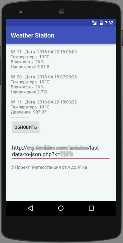
As you can see, the UI is just spartan, based on LinearLayout, nothing superfluous.
At the top of the TextView shows the ID of the sensors and their meteorological data. The “Refresh” button initiates a repeated request to the web server. Next in EditText is the only setting of the program - this is the URL of the request
http://< >/last-data-to-json.php?k=<access_key> What should be noted?
In the manifest, add lines that allow the Internet and check the status of the network connection:
<uses-permission android:name="android.permission.ACCESS_NETWORK_STATE" /> <uses-permission android:name="android.permission.INTERNET" /> Working with the network and receiving data from the website is as follows.
Use AsyncTask to create a background task separately from the main user interface thread. This background task takes the request URL and uses it to create an HttpURLConnection .
After the connection is established, AsyncTask loads the contents of the web page (JSON) as an InputStream. Next, the InputStream is converted to a string, which is decoded using JSONObject and displayed in the user interface by the onPostExecute() method.
In MainActivity.java, change the URL to your:
private static final String defUrl = "http://host/dir/last-data-to-json.php?k=< >"; It will be used by default when you first start the Android application.
Epilogue
Well, something has already earned. Then you can optimize something, replace something, you can throw everything out, but also borrow something.
A separate big sore point is energy consumption . I recommend reading comments on posts where there are a lot of practical advice.
To infinity ... and beyond.
')
Source: https://habr.com/ru/post/426019/
All Articles