Hexagon maps in Unity: save and load, textures, distances
Parts 1-3: mesh, cell colors and heights
Parts 4-7: bumps, rivers and roads
Parts 8-11: water, landforms and walls
')
Parts 12-15: saving and loading, textures, distances
Parts 16-19: Pathfinding, Player Squads, Animations
Parts 20-23: fog of war, map exploration, procedural generation
Parts 24-27: water cycle, erosion, biomes, cylindrical map
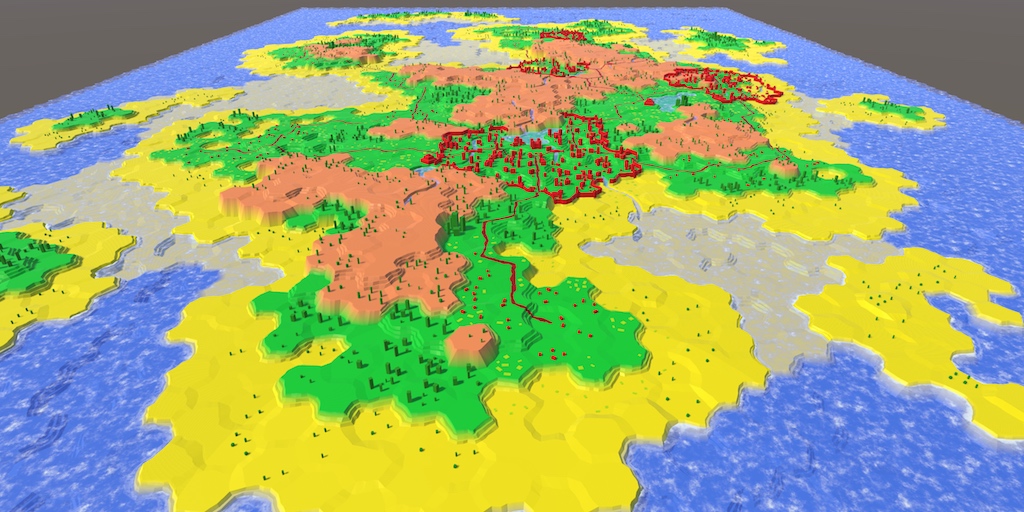
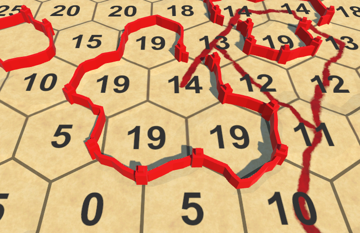
We already know how to create quite interesting maps. Now you need to learn how to save them.
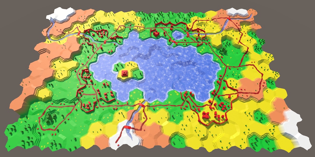
Loaded from test.map file.
When you save the map, we do not need to store all the data that we track during the execution of the application. For example, we only need to memorize the height of the cell. Its very vertical position is taken from this data, so it is not necessary to store it. In fact, it is better if we do not store these calculated metrics. This way the map data will remain correct, even if we later decide to change the height offset. The data is separated from their presentation.
Similarly, we do not need to store the exact color of the cell. You can write that the cell is green. But the exact shade of green can change when you change the visual style. For this, we can save the color index, not the colors themselves. In fact, it may be enough for us to store this index in the cells instead of real colors even at run time. This will allow later to move to a more complex visualization of the relief.
If the cells no longer have color data, then it should be stored somewhere else. The most convenient way to store it in
Like all other global data, such as noise, we can initialize these colors with a
And since now we do not assign colors directly to the cells, we will get rid of the default color.
Adjust the new colors to match the common array of the hexagon map editor.
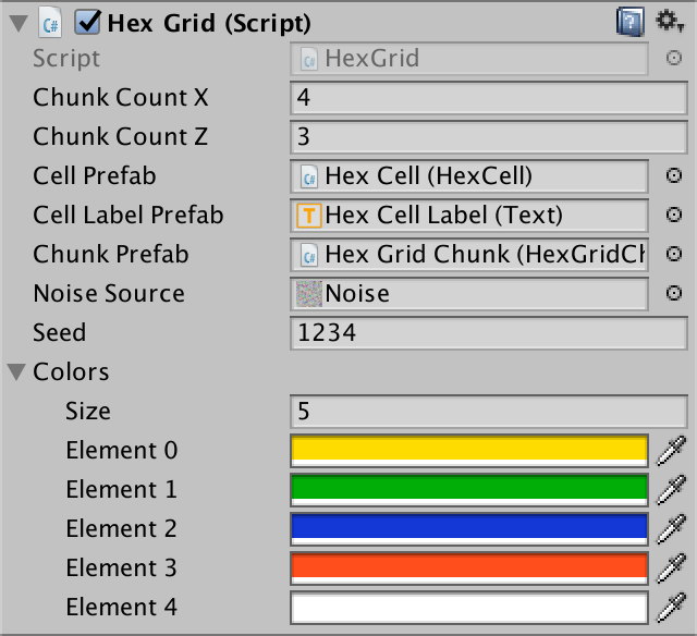
Colors added to the grid.
Remove the color field from
The color property can use this index only to get the corresponding color. It is no longer specified directly, so we will remove this part. In this case, we get a compilation error, which we will fix soon.
Add a new property to get and set a new index of the relief type.
Inside
Now we add a field and a method for managing the active index of the relief type.
We use this method as a replacement for the now missing
Although we removed the given colors from the cells, the map should work the same way as before. The only difference is that the default color is now first in the array. In my case it is yellow.
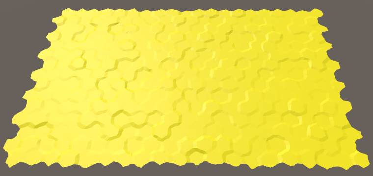
Yellow is the new default color.
unitypackage
To manage the saving and loading of the map, we use
Add two buttons to the UI ( GameObject / UI / Button ). Connect them to the buttons and give the appropriate labels. I put them in the bottom of the right pane.
Save and Load buttons.
To store the card you need to save it somewhere. As done in most games, we will store the data in a file. But where in the file system to put this file? The answer depends on which operating system the game is running on. Each OS has its own standards for storing files related to applications.
We do not need to know these standards. Unity knows the proper path we can get using the
On desktop systems, the path will contain the name of the company and product. This path is used and the editor, and assembly. Names can be configured in Edit / Project Settings / Player .
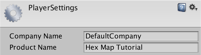
Name of company and product.
To create a file, we need to use classes from the
First we need to create the full path to the file. We use test.map as the file name . It must be added to the stored data path. Whether to insert a slash or backslash (slash or backslash) depends on the platform. This will deal with the
Next we need to access the file at this location. We do this using the
The result of calling this method will be an open data stream associated with this file. We can use it to write data to a file. And we need to remember to close the stream when we no longer need it.
At this stage, when you click the Save button, a test.map file will be created in the folder specified as the path to the stored data. If you examine this file, it will be empty and have a size of 0 bytes, because so far we have not recorded anything in it.
To write data to a file, we need a way to stream data to it. This is easiest to do with
Create a new
To transfer data to a stream, we can use the
Press the Save button and examine test.map again. Now its size is 4 bytes, because the size of the integer is 4 bytes.
Notice that we store binary data, not human readable text. Therefore, if we open the file in a text editor, we will see a set of vague characters. You will probably see the { character, for which there is nothing or there are several placeholders.
You can open the file in a hex editor. In this case, we will see 7b 00 00 00 . These are four bytes of our integer, displayed in hexadecimal notation. In ordinary decimal numbers this is 123 0 0 0 . In binary notation, the first byte looks like 01111011 .
The ASCII code for { equals 123, so this symbol can be displayed in a text editor. ASCII 0 is a null character that does not match any visible characters.
The remaining three bytes are zero, because we wrote down a number less than 256. If we recorded 256, then we would see 00 01 00 00 in the hex editor.
It is important that we close the writer. While it is open, the file system locks the file, preventing other processes from writing to it. If we forget to close it, then we block ourselves too. If we press the save button twice, then the second time we will not be able to open the stream.
Instead of closing the writer manually, we can create a
This will work because the writer and file stream classes implement the
The big advantage of
To read previously recorded data, we need to insert the code into the
In this case, we can use the
When reading, we need to explicitly specify the type of data received. To read from the integer stream, we need to use
It is necessary to consider that when receiving 123 it will be enough for us to count one byte. But at the same time in the stream will remain three bytes belonging to this integer. In addition, it does not work for numbers outside the range of 0–255. So do not do this.
unitypackage
When saving data, the important question is whether to use a human-readable format. Usually, JSON, XML and simple ASCII with some kind of structure are used as human-readable formats. Such files can be opened, interpreted and edited in text editors. In addition, they simplify the exchange of data between different applications.
However, such formats have their own requirements. Files will take up more space (sometimes much more) than when using binary data. They can also greatly increase the cost of encoding and decoding data, in terms of both runtime and memory usage.
In contrast, binary data is compact and fast. This is important when writing large amounts of data. For example, when autosaving a large card in each course of the game. therefore
we will use binary format. If you can handle it, you can work with more detailed formats.
To serialize the map, we need to store the data of each cell. To save and load a single cell, add the
Add
If we load a map, it needs to be updated after the cell data has been changed. To do this, just update all the fragments.
Finally, we replace our test code in
At the current stage, re-saving creates an empty file, and the download does nothing. Let's start gradually, by recording and loading only the
Directly assign the value to the
When saving to this file one after another, the index of the type of relief of all cells will be recorded. Since the index is an integer, its size is equal to four bytes. My map contains 300 cells, that is, the file size will be 1200 bytes.
The download reads the indexes in the order in which they are written. If you changed the colors of the cells after saving, loading the map will return the colors to the state when they were saved. Since we do not save anything else, the remaining cell data will remain the same. That is, the load will change the type of relief, but not its height, water level, relief objects, etc.
Preserving the relief type index is not enough for us. It is necessary to save and all other data. Let's start with all the fields integer. These are terrain type index, cell height, water level, city level, farm level, vegetation level, and index of particular objects. They will need to be read in the same order in which they were recorded.
Now try saving and loading the map, making changes between these operations. Everything that we included in the stored data was restored as much as we can, except for the height of the cell. This happened because when you change the height level, you need to update the vertical position of the cell. This can be done by assigning it to the property, and not the field, the value of the loaded height. But this property does extra work that we don’t need. So let's extract the code that updates the position of the cell from the
Now we can call the method when setting the property, as well as after loading the height data.
After this change, the cells will correctly change their apparent height when loading.
The presence in the cell walls and incoming / outgoing rivers is stored in Boolean fields. We can write them simply as integer. In addition, road data is an array of six boolean values that we can write using a loop.
Directions of incoming and outgoing rivers are stored in the fields
Boolean values are read using the
Now we save all the data cells, which are necessary for the complete preservation and restoration of the card. This requires nine integers and nine booleans per cell.Each boolean value is one byte, so we use a total of 45 bytes per cell. That is, a card with 300 cells requires a total of 13,500 bytes.
unitypackage
Although it seems that 13,500 bytes is not very much for 300 cells, perhaps we can get along with less. In the end, we have complete control over how data is serialized. Let's see, maybe there is a more compact way to store them.
Different levels and cell indices are stored as integer. However, they use only a small range of values. Each of them will definitely stay in the range of 0–255. This means that only the first byte of each integer will be used. The remaining three will always be zero. There is no point in storing these empty bytes. We can drop them by converting an integer to byte before writing to a stream.
Now, to return these numbers, we have to use
So we get rid of three bytes on integer, which gives a saving of 27 bytes per cell. Now we spend 18 bytes per cell, and only 5,400 bytes per 300 cells.
It is worth noting that the old map data becomes meaningless at this stage. When the old save is loaded, the data is mixed up and we get messed up cells. This is because now we read less data. If we read more data than before, we would get an error when trying to read beyond the end of the file.
The impossibility of processing old data suits us, because we are in the process of defining the format. But when we decide on the format of the save, we will need to ensure that future code can always read it. Even if we change the format, then ideally we should still be able to read the old format.
At this stage, we use four bytes for storing the data of rivers, two for each direction. For each direction we keep the presence of the river and the direction in which it flows
It seems obvious that we do not need to keep the direction of the river if it is not there. This means that cells without a river need two bytes less. In fact, it will be enough for us one byte per direction of the river, regardless of its existence.
We have six possible directions that are stored as numbers in the range of 0–5. For this, it suffices to use binary bits, because in binary form, numbers from 0 to 5 look like 000, 001, 010, 011, 100, 101 and 110. That is, five more bits remain unused in one byte. We can use one of them to indicate whether a river exists. For example, you can use the eighth bit corresponding to the number 128.
To do this, we will add 128 to it before converting the direction to byte. That is, if we have a river flowing to the north-west, we will write 133, which is equal to 10000101 in binary form. And if there is no river, we will simply write zero byte.
At the same time, we still have four unused bits, but this is normal. We can combine both directions of the river into one byte, but this will be too confusing.
To decode river data, we first need to count back bytes. If its value is not less than 128, then this means that there is a river. To get its direction, subtract 128, and then convert to
As a result, we got 16 bytes per cell. The improvement seems to be not great, but it is one of those tricks that are used to reduce the size of binary data.
We can use a similar trick to compress road data. We have six boolean values that can be stored in the first six bits of a byte. That is, each direction of the road is represented by a number that is a power of two. These are 1, 2, 4, 8, 16 and 32, or in binary form 1, 10, 100, 1000, 10000 and 100000.
To create a finished byte, we need to set the bits corresponding to the used directions of the roads. We can use the operator to get the right direction for the direction
To get the boolean value of the road back, you need to check if the bit is set. If so, then mask all other bits using the bitwise AND operator with the corresponding number. If the result is not zero, then the bit is set and the road exists.
Squeezing six bytes into one, we got 11 bytes per cell. At 300 cells, this is only 3,300 bytes. That is, having worked a little with the bytes, we reduced the file size by 75%.
Before declaring our save format complete, add one more detail. Before saving the card data, make the
This will add four empty bytes to the beginning of our data. That is, before loading the card we will have to read these four bytes.
Although these bytes are useless for the time being, they are used as a header that will ensure backward compatibility in the future. If we had not added these zero bytes, the contents of the first few bytes depended on the first cell of the map. Therefore, in the future it would be more difficult for us to figure out which version of the preservation format we are dealing with. Now we can just check the first four bytes. If they are empty, then we are dealing with the version of format 0. In future versions, it will be possible to add something else to it.
That is, if the header is non-zero, we are dealing with some unknown version. Since we cannot find out what data is there, we must refuse to load the map.
unitypackage
In this part we will add support for various map sizes, as well as saving different files.
Starting from this part, tutorials will be created in Unity 5.5.0.
Start a library of maps.
Up to this point, the grid of hexagons, we created only once - when loading the scene. Now we will make it possible to start a new card at any time. A new card will simply replace the current one.
In Awake
Add a button to the UI to create a new map. I made it big and placed it under the save and load buttons.
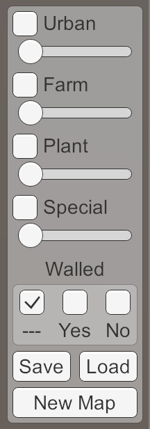
New Map Button.
Connect the On Click event of this button with the method of
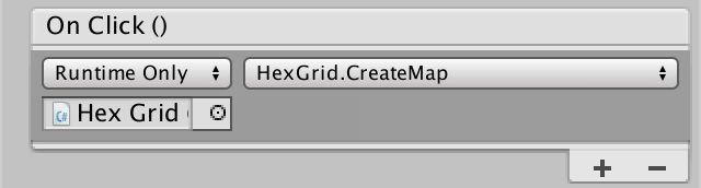
Create a map by pressing.
Now when you click on the New Map button , a new set of fragments and cells will be created. However, old ones are not automatically deleted. Therefore, as a result, we will have several meshes of maps superimposed on each other. To avoid this, we first need to get rid of old objects. This can be done by destroying all the current fragments at the beginning
For now we set the size of the map through the fields
This will lead to a compilation error, because it
The fragment has a size of 5 to 5 cells, and the default maps are 4 to 3 fragments. Therefore, in order for the cards to remain the same, we will have to use a size of 20 by 15 cells. And although we assigned default values in the code, the grid object will still not use them automatically, because the fields already existed and were set to 0 by default.
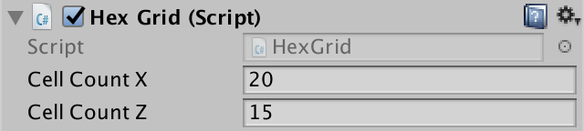
The default map size is 20 by 15.
The next step is to support the creation of maps of any size, not just the default size. To do this, add to the
However, this will only work correctly with the number of cells multiple of the fragment size. Otherwise, the integer division will create too few fragments. Although we can add support for fragments partially filled with cells, let's just forbid the use of dimensions that do not correspond to the fragments.
We can use the operator
At the current stage, the New Map button no longer works, because the method
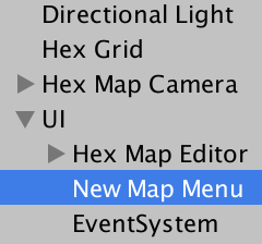
Add a new canvas to the scene ( GameObject / UI / Canvas ). We use the same settings as the existing canvas, except that its Sort Order should be equal to 1. Due to this, it will be on top of the UI of the main editor. I made both the canvas and the event system the children of a new UI object so that the scene hierarchy remains clean.
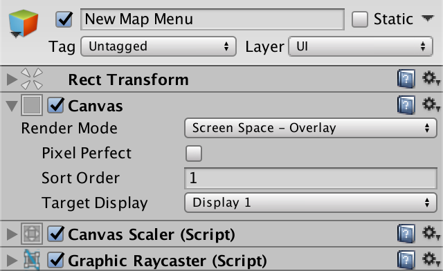
Canvas menu New Map.
Add to New Map Menu panel, covering the entire screen. It is needed to darken the background and not allow the cursor to interact with everything else when the menu is open. I gave it a uniform color, clearing its Source Image , and set it as Color (0, 0, 0, 200).
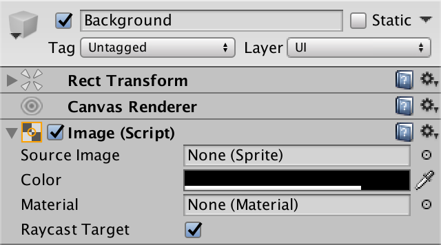
Background image settings.
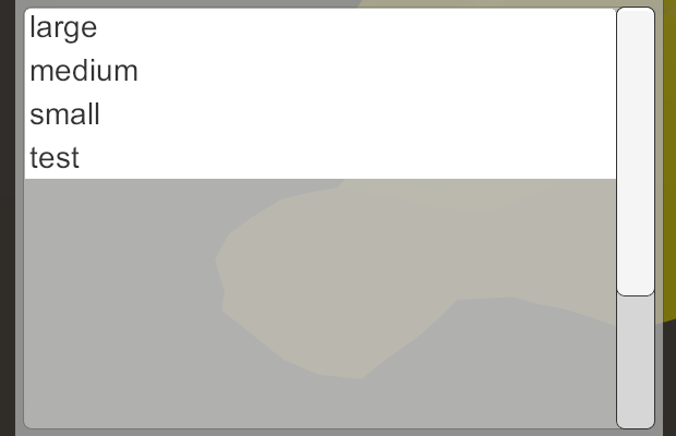
Add a menu bar to the canvas center, similar to the Hex Map Editor panels . Create a clear label and buttons for small, medium and large maps. We will also add a cancel button to it in case the player changes his mind. Having finished creating the design, we deactivate the whole New Map Menu .
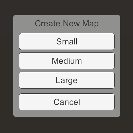
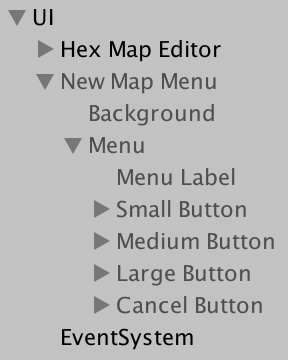
Menu New Map.
To manage the menu, create a component

Component New Map Menu.
We can open and close the popup menu by simply activating and deactivating the canvas object. Let's add in
Now connect the New Map UI button of the editor to the method

Opening the menu by pressing.
Also connect the Cancel button to the method
To create new maps, we need to call a method in the Hex Grid object
This method should not be general, because we still cannot connect it directly to button events. Instead, create one method per button that will be called
Now we can use the pop-up menu to create new maps with three different sizes! Everything works well, but we need to take care of a little detail. When the New Map Menu is active, we can no longer interact with the UI editor and edit the cells. However, we can still control the camera. Ideally, when the menu is open, the camera should be blocked.
Since we only have one camera, a quick and pragmatic solution would be to simply add a static property to it
A property
Now
There is another likely issue with the camera. When creating a new card that is smaller than the current one, the camera may be beyond the boundaries of the card. She will stay there until the player tries to move the camera. And only then will it become limited to the new card.
To solve this problem, we can add to the
Call the method inside
unitypackage
Although we can create maps of different sizes, it is not taken into account when saving and loading. This means that loading a map will result in an error or an incorrect map if the size of the current map does not match the size of the map being loaded.
To solve this problem, before loading the data cells, we need to create a new map of the appropriate size. Let's assume that we have a small map saved. In this case, everything will be fine if we create
Of course, we can store a card of any size. Therefore, a generalized solution will be to preserve the size of the map in front of the data cells.
Then we can get the true size and use it to create a map with the correct size.
Since now we can download maps of different sizes, we again face the problem of the camera position. We will solve it by checking its position in
Although this approach works with maps that we will save in the future, it will not work with old ones. And vice versa - the code from the previous part of the tutorial will not be able to correctly load new map files. To distinguish between old and new formats, we will increase the integer header value. The old format of saving without the size of the card was version 0. The new format with the size of the map will be version 1. Therefore, when recording
From now on, the maps will be saved as version 1. If we try to open them in the assembly from the previous tutorial, they will refuse to load and report an unknown map format. In fact, this will happen if we already try to load such a map. You need to change the method
In fact, if you want, we can still load version 0 maps, assuming that they all have the same size of 20 by 15. That is, the title does not have to be 1, it can be zero. Since each version requires its own approach, it
Add a
version 0 map file
As with the creation of a new map, it is theoretically possible that we will have to load a map that is incompatible with the size of the fragment. When this happens, we must interrupt the loading of the map.
Now,
Since the download overwrites all the data in the existing cells, we do not need to create a new map if the map is loaded the same size. Therefore, this step can be skipped.
unitypackage
We can save and load maps of different sizes, but always write and read test.map . Now we will add support for different files.
Instead of saving or loading the map directly, we use another pop-up menu that provides advanced file management. Create another canvas, as in the New Map Menu , but this time we will call it Save Load Menu . This menu will deal with saving and loading maps, depending on the button pressed to open it.
We will create a Save Load Menu design.as if it's a save menu. Later we will dynamically turn it into the boot menu. Like the other menu, it should have a background and menu bar, menu label and cancel button. Then add scroll view ( GameObject / UI / Scroll View ) to the menu to display the file list. Below we insert an input field ( GameObject / UI / Input Field ) to specify the names of the new maps. We also need an action button to save the map. And finally. add a Delete button to remove unwanted maps.
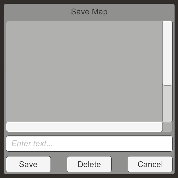

Design Save Load Menu.
By default, scroll view allows you to perform both horizontal and vertical scrolling, but we only need a list with vertical scrolling. Therefore, turn off the scrolling Horizontal and disconnect the horizontal scroll bar. Also set the value for the Movement Type clamped and disable Inertia , so that the list seems more restrictive .

Parameters File List.
Remove the Scrollbar Horizontal child from the File List object , because we don’t need it. Then change the size of the Scrollbar Vertical so that it reaches the bottom of the list.
The placeholder text of the Name Input object can be changed in its Placeholder child element . I used descriptive text, but you can just leave it blank and get rid of the placeholder.
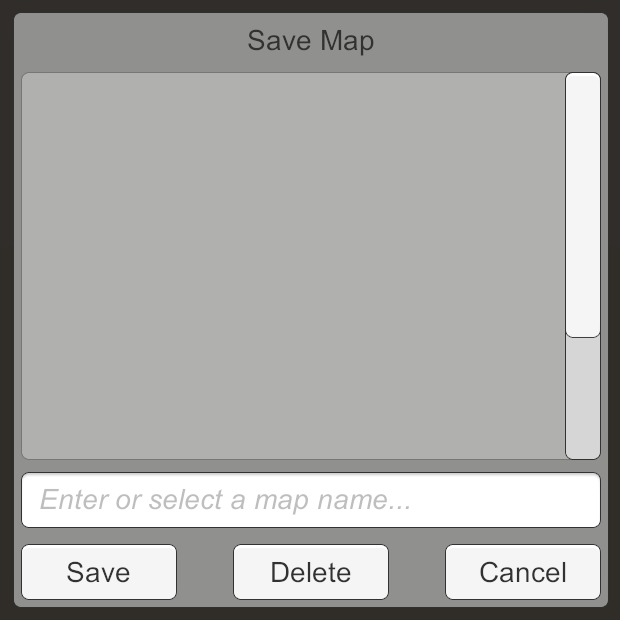
Changed menu design.
We’ve finished with the design, and now we deactivate the menu so that it is hidden by default.
For the menu to work, we need another script, in this case -
Add this component to SaveLoadMenu and give it a link to the grid object.
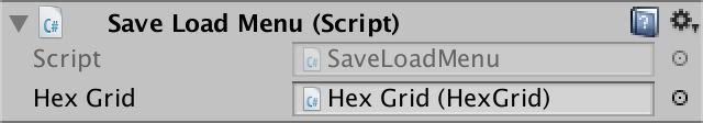
Component SaveLoadMenu.
The menu will open for saving or loading. To simplify the work, add a
Now combine the buttons Save and Load Object Hex Map Editor with the method
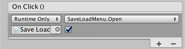
Opening the menu in save mode.
If you have not done so already, connect the Cancel button event to the method
We created the menu as a save menu, but its mode is determined by the button pressed to open. We need to change the appearance of the menu depending on the mode. In particular, we need to change the menu label and the action button label. This means that we will need links to these tags.

Connection with tags.
When the menu opens in save mode, we use the existing labels, that is, Save Map for the menu and Save for the action button. Otherwise, we are in load mode, that is, we use Load Map and Load .
Let's leave a list of files for now. The user can specify the file to be saved or loaded by entering the name of the card in the input field. To obtain this data, we need a reference to the component

Connection to the input field.
The user does not need to force to enter the full path to the map file. It will be enough just the name of the map without the .map extension . Let's add a method that takes user input and creates the right path for it. This is not possible when the input is empty, so in this case we will return
Now will be engaged in saving and loading
Since we are now loading arbitrary files, it would be nice to check that the file actually exists, and only then try to read it. If not, then we give an error and stop the operation.
Now add a general method
By attaching the Action Button event to this method , we can save and load using arbitrary map names. Since we do not reset the input field, the selected name will be saved until the next save or load. It is convenient to save or load from one file several times in a row, so we will not change anything.
Next, we will fill in the file list with all the cards that are in the data storage path. When you click on one of the items in the list, it will be used as text in the Name Input . Let's add in
We need something that is a list item. A regular button will do. Create it and reduce the height to 20 units, so that it does not take up much space vertically. It should not look like a button, so clear the Source Image link of its Image component . At the same time it will become completely white. In addition, we will make the label align to the left and that there is space between the text and the left side of the button. Having finished with button design, we will turn it into prefab.


Button-list item.
We cannot directly connect a button event to the New Map Menu , because this is a prefab and does not exist in the scene yet. Therefore, the menu item needs a link to the menu so that it can call the method when pressed
Add a component to the menu item and make the button call its method
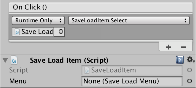
Component item.
To populate the list, you

Combining the contents of the list and prefab.
To fill this list, we use a new method. The first step is to identify the existing map files. To obtain an array of all file paths within the directory, we can use the method
Unfortunately, file order is not guaranteed. To display them in alphabetical order, we need to sort the array with
Next, we will create instances of the prefab for each element of the array. Bind the item to the menu, set its card name and make it a child of the list.
Since it
Before displaying the menu, we need to fill out the list. And since the files are likely to change, we need to do this every time the menu is opened.
When re-filling the list, we need to remove all old ones before adding new items.
Items without placement.
Now the list will display items, but they will overlap and be in a bad position. To make them turn into a vertical list, we add a Vertical Layout Group ( Component / Layout / Vertical Layout Group ) component to the Content object of the list . For the alignment to work properly, we ’ll enable Width of both Child Control Size and Child Force Expand . Both options Height must be disabled.

Use the vertical layout group.
We have a beautiful list of items. However, the size of the contents of the list does not adjust to the true number of items. Therefore, the scroll bar never changes size. We can make Content automatically resize by adding a Content Size Fitter component ( Component / Layout / Content Size Fitter ) to it. His Vertical Fit mode should be set to Preferred Size .
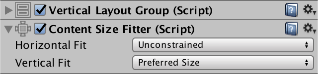

Use content size fitter.
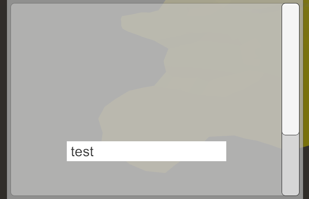
Now, with a small number of points, the scroll bar will disappear. And when there are too many items in the list that do not fit in the viewing window, the scroll bar appears and has the corresponding size.
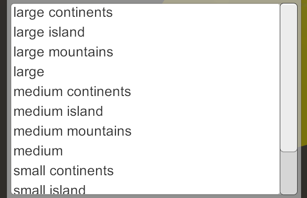
A scrollbar appears.
Now we can conveniently work with a variety of map files. However, sometimes it is necessary to get rid of some cards. For this you can use the Delete button . Create a method for this and make the button call it. If there is a selected path, simply delete it with
Here we also need to check that we are working with a really existing file. If this is not the case, then we should not try to delete it, but this does not lead to an error.
After removing the card, we do not need to close the menu. This makes it easier to delete several files at once. However, after deleting, we need to clear the Name Input , as well as update the file list.
unitypackage
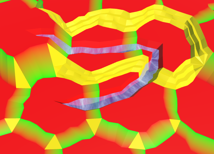
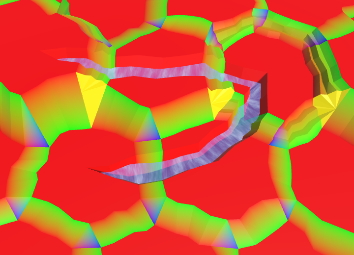
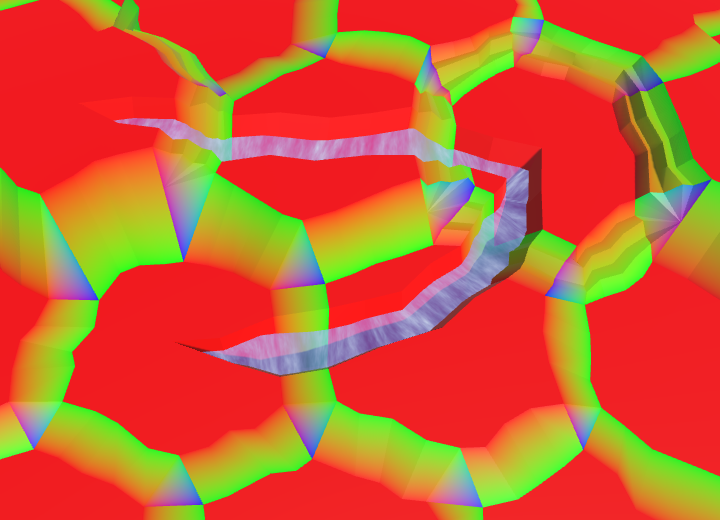
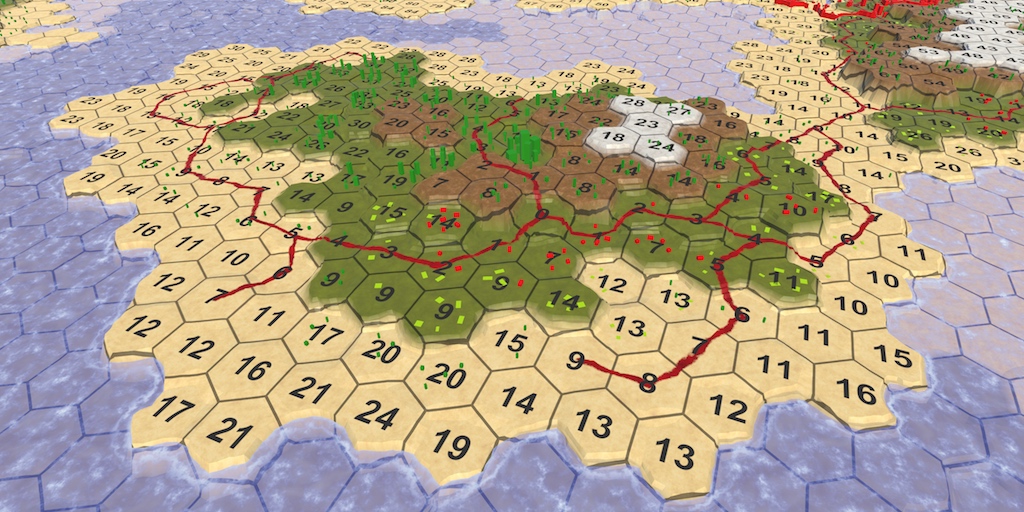
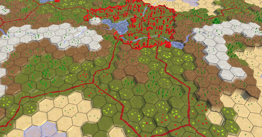
Up to this point, we used solid colors for coloring maps. Now we will apply the texture.
Drawing textures.
Although homogeneous colors are clearly distinguishable and fully cope with the task, they do not look very interesting. The use of textures will greatly increase the appeal of maps. Of course, for this we have to mix textures, not just colors. In the Rendering 3, Combining Textures tutorial , I talked about how to mix multiple textures using a splat map. In our maps of hexagons, you can use a similar approach.
In tutorial Rendering 3Only four textures are mixed, and with one splat map we can support up to five textures. At the moment we are using five different colors, so this is fine for us. However, we can add other types later. Therefore, the need to support an arbitrary number of types of relief. When using explicit texture properties, this is not possible, so you will have to apply an array of textures. Later we will create it.
When using texture arrays, we somehow need to tell the shader which textures to mix. The most complex mixing is necessary for angular triangles, which can be between three cells with their type of relief. Therefore, we need support for mixing between the three types per triangle.
Assuming that we can tell you which textures to blend, you can use the vertex colors to create a splat map for each triangle. Since in each of the cases a maximum of three textures are used, we need only three channels of color. Red will represent the first texture, green will represent the second, and blue will represent the third.

Triangle Splat map.
If the triangle needs only one texture, we use only the first channel. That is, its color will be completely red. In the case of mixing between two different types, we use the first and second channels. That is, the color of the triangle will be a mixture of red and green. And when all three types are found, it will be a mixture of red, green and blue.
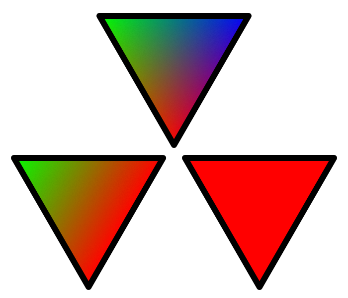
Three splat map configurations.
We will use these splat map configurations regardless of which textures actually blend. That is, the splat map will always be the same. Only the textures will change. How to do this, we will find out later.
We need to change
Let's start with replacing the color of the cell centers by default. There is no blending, so we just use the first color, that is, red.
Red cell centers.
The cell centers are now red. All of them use the first of the three textures, no matter what the texture is. Their splat maps are the same, regardless of the color with which we paint the cells.
We changed the segments only inside the cells without rivers flowing through them. We need to do the same for the segments adjacent to the rivers. In our case, this is a strip of an edge, and a fan of edge triangles. Here we also need only red.
Red segments adjacent to rivers.
Next, we need to take care of the geometry of the rivers inside the cells. All of them should also turn red. For a start, let's start the beginning and end of the rivers.
And then the geometry that makes up the banks and the river bed. I grouped calls to the color method to make the code easier to read.
Red river along the cells.
All edges are different, because they are located between cells, which may have different types of relief. We use the first color for the current cell type, and the second color for the neighbor type. As a result, the splat map will become a red-green gradient, even if both cells are of the same type. If both cells use the same texture, it will simply become a mixture of the same texture on both sides.
Red-green edges, with the exception of ledges.
The edges with ledges are slightly more complicated, because they have additional vertices. Fortunately, the existing interpolation code works fine with the splat map colors. Just use the first and second colors, not the colors of the cells of the beginning and end.

Red-green edge ledges.
The corners of the cells are the most difficult because they have to mix three different textures. We use red for the lower top, green for the left and blue for the right. Let's start with the corners of one triangle.

Red-green-blue corners, with the exception of ledges.
Here we can again use the existing color interpolation code for ledges. Just interpolation is performed between three, not two colors. First consider the ledges that are not located near the cliffs.
Red-green-blue corner ledges, except for the ledges along the cliffs.
When it comes to cliffs, we need to use the method
Change it
And do the same for
Full splat map of relief.
unitypackage
Now that our terrain has a splat map, we can transfer a texture collection to the shader. We cannot simply assign a C # texture array to the shader, because the array must exist in the GPU memory as a single entity. We should use special object
Unfortunately, Unity Editor support for texture arrays in version 5.5 is minimal. We cannot simply create an array of textures and assign textures to it. We have to do it manually. We can either create an array of textures in Play mode, or create an asset in the editor. Let's create an asset.
To create an array of textures, we will assemble our own master. Create a script
We can open the wizard through a generic static method
To access the wizard through the editor, we need to add this method to the Unity menu. This can be done by adding an attribute to the method
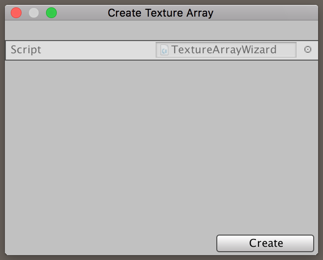
Our custom master.
Using the new menu item, you can open the popup menu of our custom wizard. It is not very beautiful, but it is suitable for solving the problem. However, it is still empty. To create an array of textures, we need an array of textures. Add for him in the master common field. The standard wizard GUI will display it, as the standard inspector does.
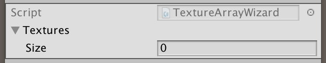
Wizard with textures.
When you click the Create button of the wizard, it will disappear. In addition, Unity will complain that there is no method
Here we will create our array of textures. At least if the user added texture to the wizard. If not, then there is nothing to create and the work must be stopped.
The next step is to ask where to save the texture array array. The save file panel can be opened by the method
If we have the right path, then we can move on and create a new object
Since the texture array is a single GPU resource, it uses the same filtering and folding modes for all textures. Here we again use the first texture to adjust all this.
Now we can copy the textures into an array using the method
At this stage, we have in memory the correct array of textures, but it is not yet an asset. The final step will be a call
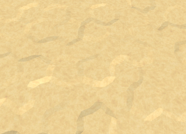
To create a real array of textures, we need the original textures. Here are five textures that match the colors we used up to this point. Yellow becomes sand, green becomes grass, blue becomes earth, orange becomes stone, and white becomes snow.


Textures of sand, grass, earth, stone and snow.
Note that these textures are not photographs of this relief. These are light pseudo-random patterns that I created using NumberFlow . I tried to create recognizable types and relief details that do not conflict with abstract polygonal relief. Photorealism turned out to be inappropriate. In addition, despite the fact that the patterns add variations, they have few distinct features that would make repetitions immediately noticeable.
Add these textures to the wizard array, making sure that their order matches the colors. That is, first sand, then grass, earth, stone, and finally snow.


Create an array of textures.
After creating an array of textures, select it and look at it in the inspector.

Texture array inspector.
This is the simplest display of a piece of texture array data. Notice that there is an Is Readable switch that is initially enabled. Since we do not need to read the pixel data from the array, turn it off. We cannot do this in the wizard, because we have
(In Unity 5.6 there is a bug that corrupts texture arrays in assemblies on several platforms. You can bypass it without disabling Is Readable .)
It is also worth noting that there is a Color Space field, which is assigned the value 1. This means that the textures are assumed to be in gamma space, which is true. If they were to be in linear space, then the field had to be assigned the value 0. In fact, the designer
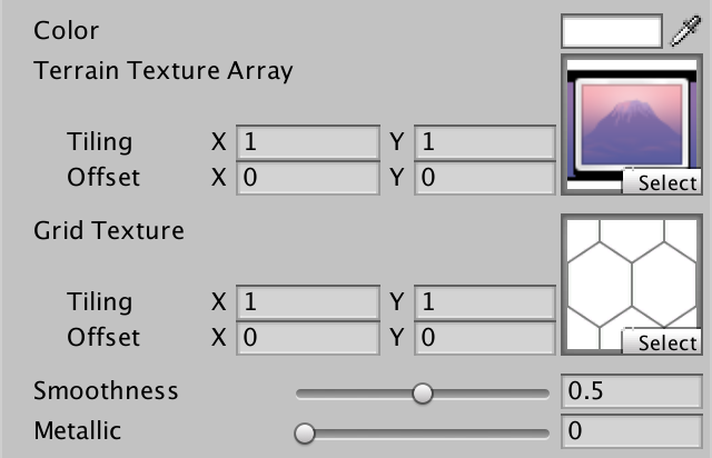
Now that we have an array of textures, we need to teach the shader to work with it. So far, for rendering terrain, we use the VertexColors shader . Since now instead of colors we use textures, we rename it to Terrain . Then turn its _MainTex parameter into an array of textures and assign an asset to it.

Material relief with an array of textures.
To enable texture arrays on all platforms supporting them, increase the target level of the shader from 3.0 to 3.5.
Since the variable
As in other shaders, for sampling the textures of the relief we need the coordinates of the XZ world. Therefore, we will add a position in the world to the input shader structure. We also remove the default UV coordinates, because we don’t need them.
To sample an array of textures, we need to use a macro
The third coordinate is used as an index of an array of textures, as in a regular array. Since the coordinates have float values, before indexing the array, the GPU rounds them. Since we do not know yet what texture is needed, let's always use the first one. Also, the color of the vertex will not affect the final result, because it is a splat map.
Everything became sand.
unitypackage
We need a splat map of relief, mixing three types per triangle. We have an array of textures with a texture for each type of relief. We have a shader that samples the array of textures. But so far we have no opportunity to tell the shader which textures to choose for each triangle.
Since each triangle mixes up to three types in itself, we need to associate three indices with each triangle. We cannot store information for triangles, so we have to store indexes for vertices. All three vertices of the triangle will simply store the same indices as in the case of solid color.
We can use one of the UV mesh sets for storing indexes. Since three indexes are stored at each vertex, the existing 2D UV sets will not be enough. Fortunately, UV sets can contain up to four coordinates. Therefore, we will add to the
Enable terrain types for the Hex Grid Chunk Prefab Sub Terrain child .
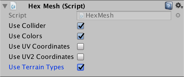
Use relief types.
If necessary, we will take another list
In the process of applying the mesh data, we save the terrain types in the third UV set. Because of this, they will not conflict with the other two sets if we ever decide to use them together.
To set the types of relief triangle we use
Mixing in quad works similarly. All four vertices have the same types.
Now we need to add types to the mesh data in
After the colors we add terrain types. Since the types in the triangle can be different, it must be a parameter that replaces the color. Use this simple type to create
Now we need to change all the calls to this method, replacing the color argument with the index of the cell type relief. Make this change to
At this stage, when you start the Play mode, errors will appear indicating that the third set of UV meshes are out of bounds. It happened because we are not adding relief types to each triangle and quad. So let's continue to change
Now, when creating the edge band, we need to know which types of relief are on both sides. Therefore, we add them as parameters, and then create a vector of types, the two channels of which are assigned these types. The third channel is not important, so just equate it to the first. After adding colors, add to quad types.
Now we need to change the challenges
Next, the simplest edge case
The same applies to
The simplest case of a corner is a simple triangle. The lower cell transmits the first type, the left - the second, and the right - the third. With their help, create a vector of types and add it to the triangle.
We use the same approach in
When mixing ledges and cliffs, we need to use
In
The same applies to
The last method requiring change is this
At this stage, the meshes contain the necessary relief indices. All we have to do is force the Terrain shader to use them. In order for indexes to fall into a fragmentary shader, we need to first pass them through the vertex shader. We can do this in our own vertex function, as we did in the Estuary shader . In this case, we add a field to the input structure
We need to sample the array of textures three times per fragment. Therefore, let's create a convenient function for creating texture coordinates, sampling an array and modulating a sample with a splat map for a single index.
Using this function, we will simply sample the array of textures three times and combine the results.

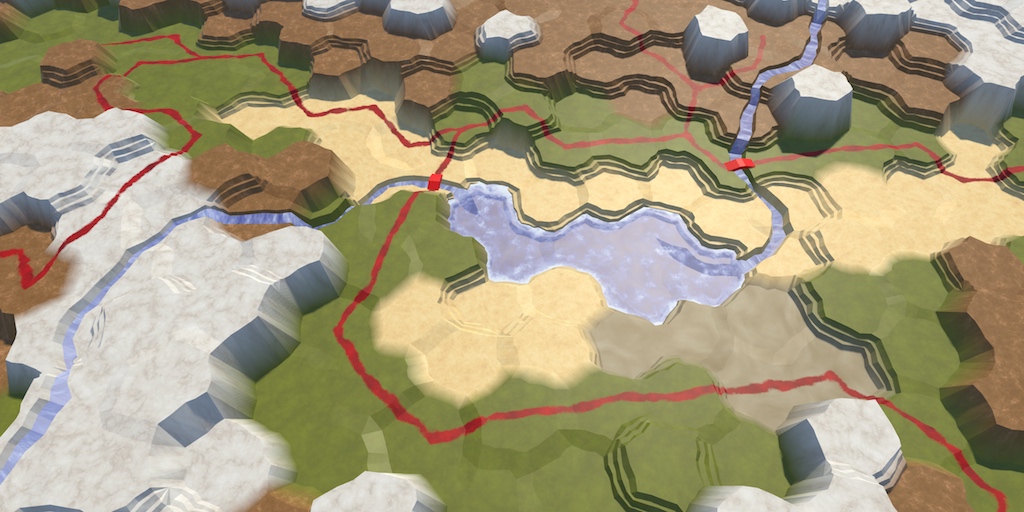
Textured relief.
Now we can draw relief textures. They are mixed just like solid colors. Since we use the coordinates of the world as UV coordinates, they do not change with altitude. As a result, along the sharp cliffs textures are stretched. If the textures are neutral enough and very variable, the results will be acceptable. Otherwise, we get big ugly stretch marks. You can try to hide it with additional geometry or textures of cliffs, but we will not do this in the tutorial.
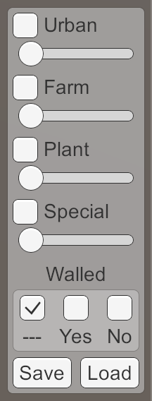
Now, when we use textures instead of colors, it will be logical to change the editor panel. We can create a beautiful interface that can even display relief textures, but I will focus on abbreviations corresponding to the style of the existing scheme.
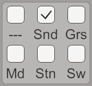
Variants of choice of relief.
In addition, you
You
Finally, an array of colors is also not needed in
unitypackage
Having created quality maps, we will begin to navigate.
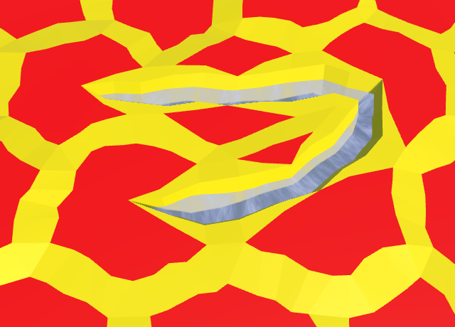
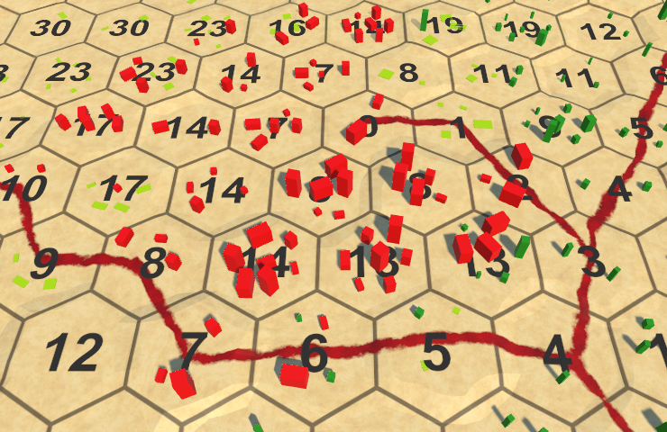
The shortest path is not always straight.
Navigation on the map is performed by moving from cell to cell. To get somewhere, you need to go through a number of cells. To estimate the distances it was easier, let's add the option to display the grid of hexagons on which our map is based.
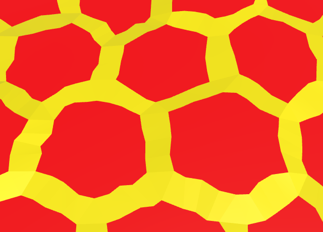
Despite the irregularities of the mesh of the map, the underlying grid is ideally even. We can show this by projecting a grid pattern onto the map. This can be done using a repeating mesh texture.

Repeating mesh texture.
The texture shown above contains a small part of the grid of hexagons, covering 2 to 2 cells. This area is rectangular, not square. Since the texture itself is a square, the pattern looks stretched. When sampling, we need to compensate for this.
To project the mesh pattern, we need to add a texture property to the Terrain shader .
Relief material with mesh texture.
Sample the texture using the XZ coordinates of the world, and then multiply it by albedo. Since the grid lines on the texture are gray, this will weave the pattern into the relief.
Albedo multiplied by a fine grid.
We need to scale the pattern to match the cells of the map. The distance between the centers of neighboring cells is 15, it must be doubled to move up two cells. That is, we need to divide the coordinates of the V grid by 30. The inner radius of the cells is 5√3, and to move two cells to the right, you need four times as much. Therefore, it is necessary to divide the coordinates of the U grid by 20√3.

The correct size of the grid cells.
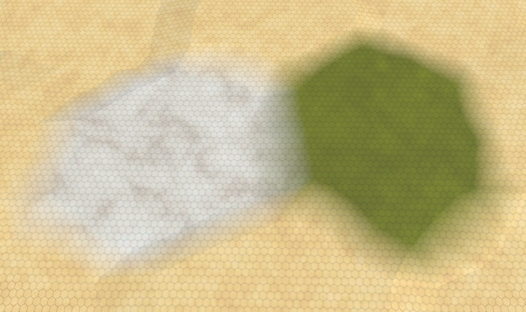
Now the grid lines correspond to the map cells. Like terrain textures, they ignore the height, so lines will be stretched along the line breaks.
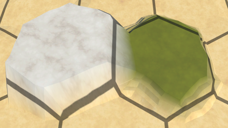
Projecting onto cells with height.
Deformation of the grid is usually not so bad, especially if you look at the map from a long distance.
Grid in the distance.
Although the display of the grid is convenient, it is not always required. For example, you should turn it off when you take a screenshot. In addition, not everyone prefers to see the grid all the time. So let's make it optional. We will add the multi_compile directive to the shader to create variants with and without a grid. For this we use the keyword
When declaring a variable,
Since the keyword is

Editor March hexagons with reference to the material.
Add a Grid switch to the UI and connect it to the method
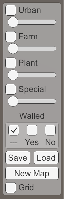
Grid switch.
Now in Play mode we can switch the display of the grid. During the first check, the grid is initially disabled and becomes visible when we enable the switch. When it is turned off, the grid will disappear again. However, if we exit Play mode when the grid is visible, the next time Play mode is started, it will be turned on again, although the switch is turned off.
This is because we are changing the keyword for the common Terrain material . We edit the asset of the material, so the change is saved in the Unity editor. In the assembly, it will not be saved.
To always start the game without a grid, we will disable the keyword
unitypackage
If we want to control the movement on the map, then we need to interact with it. At a minimum, we need to select a cell as the starting point of the path. But when you click on a cell, it will be edited. We can disable all editing options manually, but this is inconvenient. In addition, we do not want movement calculations to be performed while editing the map. So let's add a switch that determines whether we are in edit mode.
Add to the
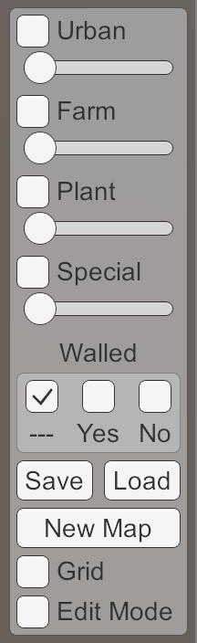
Editing mode switch.
To really disable editing, let's make the call
While we do not have units of measure to move around the map. Instead, we visualize the distances of movement. To do this, you can use existing cell labels. Therefore, we will make them visible when editing mode is disabled.
Since we start with the navigation mode, the default labels should be included. He is currently
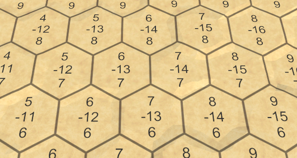
Label Coordinates.
The coordinates of the cells now become visible immediately after starting the Play mode. But we do not need coordinates, we use labels to display distances. Since you only need one number per cell, you can increase the font size so that they read better. Change the Hex Cell Label prefab to use bold font size 8.
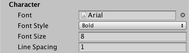
Tags are in bold size 8.
Now, after launching Play mode, we will see large labels. Only the first coordinates of the cell are visible, the rest are not placed in the label.
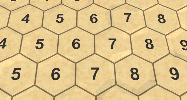
Large tags.
Since we don’t need coordinates anymore, we’ll remove the
You can also remove the Labels switch and its associated method from the UI

There is no more switch method.
unitypackage
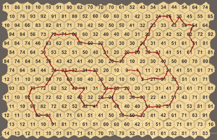
Now that we have a tagged navigation mode, we can begin to display distances. We will select a cell and then display the distance from this cell to all the cells on the map.
To track the distance to the cell, add to the
When the distance is set, we need to update the cell label to display its value.
Make the common property get and set the distance to the cell, as well as update its label.
Add to the
If the edit mode is not enabled, then we
Now in the navigation mode after touching one of them, all cells display zero. But, of course, they should display the true distance to the cell. To calculate the distance to them, we can use the coordinates of the cell. Therefore, suppose you
Now add to the
As a result, we get the offset along X relative to the selected cell. But the distances can not be negative, so you need to return the difference of coordinates X modulo.
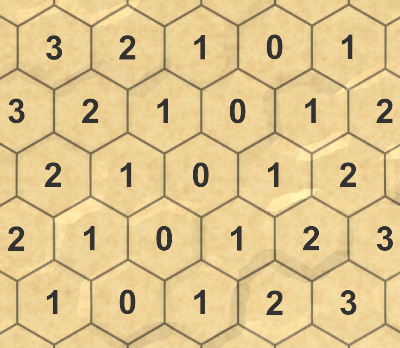
Distances in X.
So we get the right distances, only if we take into account only one dimension. But in the grid of hexagons three dimensions. So let's add distances in all three dimensions and see what it gives us.
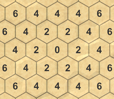
The sum of the XYZ distances.
It turns out that we get double the distance. That is, to get the correct distance, this amount should be divided in half.

Real distances.
unitypackage
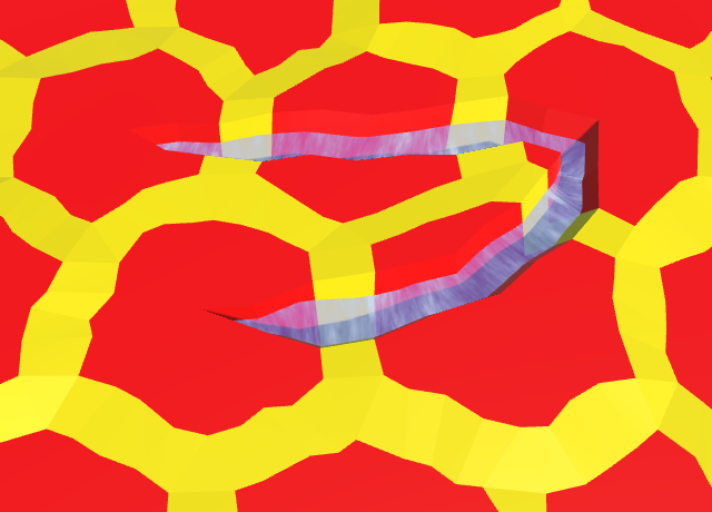
The distances we calculate correspond to the shortest paths from the selected cell to every other cell. We can not find a shorter way. But these paths are guaranteed to be correct if the route does not block anything. Cliffs, water and other obstacles can make us go around. Some cells may not be able to be reached at all.
To find a way around obstacles, we need to use a different approach instead of simply calculating the distance between the coordinates. We can no longer treat each cell separately. We will have to perform a search on the map until we find every cell that can be reached.
Map search is an iterative process. To understand what we are doing, it would be useful to see each stage of the search. We can do this by turning the search algorithm into a quortenine, for which we will need a search space
We need to make it so that at any time only one search is active. Therefore, before starting a new search, we stop all the Korutins.
In addition, we need to complete the search when loading a new map.
Even before we start the search, we know that the distance to the selected cell is zero. And, of course, the distance to all its neighbors is 1 if they can be reached. Then we can take a look at one of these neighbors. This cell most likely has its own neighbors, which can be reached and which have not yet calculated the distance. If so, then the distance to these neighbors should be 2. We can repeat this process for all neighbors at a distance of 1. After that we repeat it for all neighbors at a distance of 2. And so on, until we reach all the cells.
That is, first we find all the cells at a distance of 1, then we find everything at a distance of 2, then at a distance of 3, and so on, until we finish. This ensures that we find the smallest distance to each reachable cell. This algorithm is called breadth-first search.
To make it work, we need to know if we have already determined the distance to the cell. Often, cells are placed in a collection called a ready-made or closed set for this. But we can set the distance to the cell value
You can also use this to hide all unvisited cells by changing
Next, we need to track the cells that need to be visited, and the order of their visit. Such a collection is often called a border or an open set. We just need to process the cells in the same order in which we met them. You can use a queue for this
From this point on, the algorithm performs a loop while there is something in the queue. At each iteration, the frontmost cell is extracted from the queue.
Now we have the current cell, which can be at any distance. Next, we need to add all its neighbors to the queue one step further from the selected cell.
But we need to add only those cells that have not yet been assigned a distance.
Search wide.
After making sure that a wider search finds the correct distances on a flat map, we can begin to add obstacles. This can be done by refusing to add cells to the queue if certain conditions are met.
In fact, we are already missing some cells: those that do not exist, and those to which we have already indicated the distance. Let's rewrite the code so that we explicitly skip the neighbors in this case.
Let's also skip all the cells that are under water. This means that when searching for the shortest distances we consider only the movement on the ground.
Distances without moving through the water.
The algorithm still finds the shortest distances, but now it avoids all the water. Therefore, submarine cells never receive distances, as do isolated plots of land. An underwater cell receives a distance only if it is selected.
Also, to determine the possibility of visiting a neighbor, we can use the type of edge. For example, you can make the cliffs block the path. If you allow movement on the slopes, the cells on the other side of the cliff can still be reachable, only along other paths. Therefore, they can be at very different distances.
Distances without crossing cliffs.
unitypackage
We can avoid cells and edges, but these options are binary. It can be imagined that it is easier to move in some directions than in others. In this case, the distance is measured in labor or time.
It will be logical that it is easier and faster to travel along the roads, so let's make the intersection of the edges with the roads less costly. Since we use integer values to set the distance, we will leave the cost of traveling on roads equal to 1, and we will increase the cost of crossing other edges to 10. This is a big difference, which allows us to immediately see if we get the right results.
Roads with wrong distances.
Unfortunately, it turns out that a wide search cannot work with variable translation costs. He assumes that the cells are added to the border in order of increasing distance, but for us this is irrelevant. We need a priority queue, that is, a queue that sorts itself. There are no standard priority queues, because you cannot program them so that they fit all situations.
We can create our own queue with priority, but we will leave its optimization for the next tutorial. For now, we simply replace the queue with a list that has a method
To make the border true, we need to sort it after adding a cell to it. In fact, we can postpone sorting until all the neighbors of the cell are added, but, I repeat, we are not interested in optimizations yet.
We want to sort the cells by distance. To do this, we need to call the list sorting method with reference to the method that performs this comparison.
The sorted border is still not valid.
After the border began to be sorted, we began to get better results, but errors still exist. This is because when a cell is added to the boundary, we do not necessarily find the shortest distance to that cell. This means that now we can no longer miss neighbors who have already been assigned a distance. Instead, we need to check if we have found a shorter way. If so, then we need to change the distance to the neighbor, instead of adding it to the border.
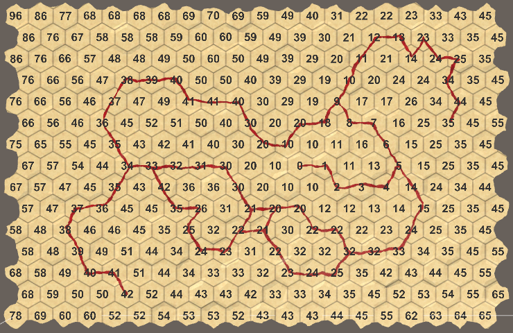
The correct distances.
Now, when we get the right distances, we start to consider the cost of moving. You may notice that the distances to some cells are initially too large, but are corrected when they are removed from the border. This approach is called the Dijkstra algorithm, it is named after Edsger Dijkstra, who first invented it.
We do not want to limit ourselves to differing costs only for roads. For example, you can reduce the cost of crossing flat edges without roads to 5, leaving 10 for slopes without roads.
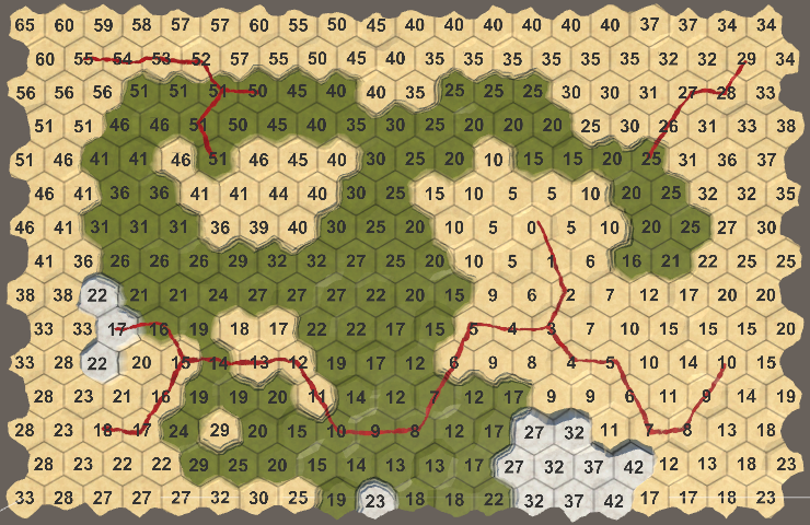
To overcome the slopes need to make more work, and the roads are always fast.
We can add costs in the presence of terrain objects. For example, in many games in the woods to move more difficult. In this case, we simply add to the distance all levels of objects. And here again the road accelerates everything.
Objects slow down if there is no road.
Finally, let's take the walls into account. Walls should block movement if the road does not pass through them.
The walls do not let us through, you need to look for the gate.
unitypackage
Parts 4-7: bumps, rivers and roads
Parts 8-11: water, landforms and walls
')
Parts 12-15: saving and loading, textures, distances
Parts 16-19: Pathfinding, Player Squads, Animations
Parts 20-23: fog of war, map exploration, procedural generation
Parts 24-27: water cycle, erosion, biomes, cylindrical map
Part 12: Save and Load
- We track the type of relief instead of color.
- Create a file.
- Write the data to a file, and then read it.
- Serialize these cells.
- Reduce the file size.
We already know how to create quite interesting maps. Now you need to learn how to save them.
Loaded from test.map file.
Relief type
When you save the map, we do not need to store all the data that we track during the execution of the application. For example, we only need to memorize the height of the cell. Its very vertical position is taken from this data, so it is not necessary to store it. In fact, it is better if we do not store these calculated metrics. This way the map data will remain correct, even if we later decide to change the height offset. The data is separated from their presentation.
Similarly, we do not need to store the exact color of the cell. You can write that the cell is green. But the exact shade of green can change when you change the visual style. For this, we can save the color index, not the colors themselves. In fact, it may be enough for us to store this index in the cells instead of real colors even at run time. This will allow later to move to a more complex visualization of the relief.
Moving an array of colors
If the cells no longer have color data, then it should be stored somewhere else. The most convenient way to store it in
HexMetrics . So let's add an array of colors to it. public static Color[] colors; Like all other global data, such as noise, we can initialize these colors with a
HexGrid . public Color[] colors; … void Awake () { HexMetrics.noiseSource = noiseSource; HexMetrics.InitializeHashGrid(seed); HexMetrics.colors = colors; … } … void OnEnable () { if (!HexMetrics.noiseSource) { HexMetrics.noiseSource = noiseSource; HexMetrics.InitializeHashGrid(seed); HexMetrics.colors = colors; } } And since now we do not assign colors directly to the cells, we will get rid of the default color.
// public Color defaultColor = Color.white; … void CreateCell (int x, int z, int i) { … HexCell cell = cells[i] = Instantiate<HexCell>(cellPrefab); cell.transform.localPosition = position; cell.coordinates = HexCoordinates.FromOffsetCoordinates(x, z); // cell.Color = defaultColor; … } Adjust the new colors to match the common array of the hexagon map editor.
Colors added to the grid.
Refactoring cells
Remove the color field from
HexCell . Instead, we will store the index. And instead of the color index, we use a more general relief type index. // Color color; int terrainTypeIndex; The color property can use this index only to get the corresponding color. It is no longer specified directly, so we will remove this part. In this case, we get a compilation error, which we will fix soon.
public Color Color { get { return HexMetrics.colors[terrainTypeIndex]; } // set { // … // } } Add a new property to get and set a new index of the relief type.
public int TerrainTypeIndex { get { return terrainTypeIndex; } set { if (terrainTypeIndex != value) { terrainTypeIndex = value; Refresh(); } } } Editor refactoring
Inside
HexMapEditor remove all code related to colors. This will fix the compilation error. // public Color[] colors; … // Color activeColor; … // bool applyColor; … // public void SelectColor (int index) { // applyColor = index >= 0; // if (applyColor) { // activeColor = colors[index]; // } // } … // void Awake () { // SelectColor(0); // } … void EditCell (HexCell cell) { if (cell) { // if (applyColor) { // cell.Color = activeColor; // } … } } Now we add a field and a method for managing the active index of the relief type.
int activeTerrainTypeIndex; … public void SetTerrainTypeIndex (int index) { activeTerrainTypeIndex = index; } We use this method as a replacement for the now missing
SelectColor method. Connect the color widgets in the UI with SetTerrainTypeIndex , leaving everything else unchanged. This means that a negative index is still in use and indicates that the color should not change.EditCell so that the relief type index is assigned to the cell being edited. void EditCell (HexCell cell) { if (cell) { if (activeTerrainTypeIndex >= 0) { cell.TerrainTypeIndex = activeTerrainTypeIndex; } … } } Although we removed the given colors from the cells, the map should work the same way as before. The only difference is that the default color is now first in the array. In my case it is yellow.
Yellow is the new default color.
unitypackage
Saving data in a file
To manage the saving and loading of the map, we use
HexMapEditor . We will create two methods that will deal with this, and for the time being we will leave them empty. public void Save () { } public void Load () { } Add two buttons to the UI ( GameObject / UI / Button ). Connect them to the buttons and give the appropriate labels. I put them in the bottom of the right pane.
Save and Load buttons.
File location
To store the card you need to save it somewhere. As done in most games, we will store the data in a file. But where in the file system to put this file? The answer depends on which operating system the game is running on. Each OS has its own standards for storing files related to applications.
We do not need to know these standards. Unity knows the proper path we can get using the
Application.persistentDataPath . You can check how it will be with you in the Save method by outputting it to the console and pressing the button in the Play mode. public void Save () { Debug.Log(Application.persistentDataPath); } On desktop systems, the path will contain the name of the company and product. This path is used and the editor, and assembly. Names can be configured in Edit / Project Settings / Player .
Name of company and product.
Why can't I find the Library folder on a Mac?
Library folder is often hidden. The way in which it can be displayed depends on the version of OS X. If you are not old, select the home folder in Finder and go to Show View Options . There is a checkbox for the Library folder.
What about webgl?
WebGL games cannot access the user's file system. Instead, all file operations are redirected to the in-memory file system. It is transparent to us. However, in order to save the data, you will need to manually order a web page to reset the data in the browser storage.
File creation
To create a file, we need to use classes from the
System.IO namespace. Therefore, we add a using statement for it over the HexMapEditor class. using UnityEngine; using UnityEngine.EventSystems; using System.IO; public class HexMapEditor : MonoBehaviour { … } First we need to create the full path to the file. We use test.map as the file name . It must be added to the stored data path. Whether to insert a slash or backslash (slash or backslash) depends on the platform. This will deal with the
Path.Combine method. public void Save () { string path = Path.Combine(Application.persistentDataPath, "test.map"); } Next we need to access the file at this location. We do this using the
File.Open method. Since we want to write data to this file, we need to use its create mode. At the same time, at the specified path, either a new file will be created, or an existing file will be replaced. string path = Path.Combine(Application.persistentDataPath, "test.map"); File.Open(path, FileMode.Create); The result of calling this method will be an open data stream associated with this file. We can use it to write data to a file. And we need to remember to close the stream when we no longer need it.
string path = Path.Combine(Application.persistentDataPath, "test.map"); Stream fileStream = File.Open(path, FileMode.Create); fileStream.Close(); At this stage, when you click the Save button, a test.map file will be created in the folder specified as the path to the stored data. If you examine this file, it will be empty and have a size of 0 bytes, because so far we have not recorded anything in it.
Write to file
To write data to a file, we need a way to stream data to it. This is easiest to do with
BinaryWriter . These objects allow you to write primitive data to any stream.Create a new
BinaryWriter object, and its argument will be our file stream. Closing the writer closes the stream that it uses. Therefore, we no longer need to store a direct link to the stream. string path = Path.Combine(Application.persistentDataPath, "test.map"); BinaryWriter writer = new BinaryWriter(File.Open(path, FileMode.Create)); writer.Close(); To transfer data to a stream, we can use the
BinaryWriter.Write method. There is a variant of the Write method for all primitive types, such as integer and float. It can also write strings. Let's try write integer 123. BinaryWriter writer = new BinaryWriter(File.Open(path, FileMode.Create)); writer.Write(123); writer.Close(); Press the Save button and examine test.map again. Now its size is 4 bytes, because the size of the integer is 4 bytes.
Why does my file manager show that the file takes up more space?
Because file systems divide space into blocks of bytes. They do not track individual bytes. Since test.map occupies only four bytes so far, it requires one block of storage space.
Notice that we store binary data, not human readable text. Therefore, if we open the file in a text editor, we will see a set of vague characters. You will probably see the { character, for which there is nothing or there are several placeholders.
You can open the file in a hex editor. In this case, we will see 7b 00 00 00 . These are four bytes of our integer, displayed in hexadecimal notation. In ordinary decimal numbers this is 123 0 0 0 . In binary notation, the first byte looks like 01111011 .
The ASCII code for { equals 123, so this symbol can be displayed in a text editor. ASCII 0 is a null character that does not match any visible characters.
The remaining three bytes are zero, because we wrote down a number less than 256. If we recorded 256, then we would see 00 01 00 00 in the hex editor.
Should not 123 be stored as 00 00 00 7b?
The alternative to it is big-endian, in which the most significant bytes are stored first. This corresponds to the usual order of numbers in numbers. 123 is a hundred and twenty-three, because we mean big-endian. If it were little-endian, then 123 would mean three hundred and twenty-one.
BinaryWriter uses little-endian format to save numbers. This means that the least significant bytes are written first. This format has been used by Microsoft in developing the .Net framework. It was probably chosen because little-endian format is used in Intel CPUs.The alternative to it is big-endian, in which the most significant bytes are stored first. This corresponds to the usual order of numbers in numbers. 123 is a hundred and twenty-three, because we mean big-endian. If it were little-endian, then 123 would mean three hundred and twenty-one.
Make it so that resources are released.
It is important that we close the writer. While it is open, the file system locks the file, preventing other processes from writing to it. If we forget to close it, then we block ourselves too. If we press the save button twice, then the second time we will not be able to open the stream.
Instead of closing the writer manually, we can create a
using block for this. It defines the scope within which the writer is valid. When executable code goes beyond this scope, the writer is deleted and the stream is closed. using ( BinaryWriter writer = new BinaryWriter(File.Open(path, FileMode.Create)) ) { writer.Write(123); } // writer.Close(); This will work because the writer and file stream classes implement the
IDisposable interface. These objects have a Dispose method, which is indirectly called when going outside the scope of using .The big advantage of
using is that it works no matter how the execution of the program goes out of scope. Early returns, exceptions and errors do not interfere with it. In addition, it is very concise.Data acquisition
To read previously recorded data, we need to insert the code into the
Load method. As with saving, we need to create a path and open the file stream. The difference is that now we open the file for reading, not for writing. And instead of writer, we will need a BinaryReader . public void Load () { string path = Path.Combine(Application.persistentDataPath, "test.map"); using ( BinaryReader reader = new BinaryReader(File.Open(path, FileMode.Open)) ) { } } In this case, we can use the
File.OpenRead method to open the file to read it. using (BinaryReader reader = new BinaryReader(File.OpenRead(path))) { } Why we can not use when writing File.OpenWrite?
This method creates a stream that adds data to existing files, rather than replacing them.
When reading, we need to explicitly specify the type of data received. To read from the integer stream, we need to use
BinaryReader.ReadInt32 . This method reads a 32-bit integer, that is, four bytes. using (BinaryReader reader = new BinaryReader(File.OpenRead(path))) { Debug.Log(reader.ReadInt32()); } It is necessary to consider that when receiving 123 it will be enough for us to count one byte. But at the same time in the stream will remain three bytes belonging to this integer. In addition, it does not work for numbers outside the range of 0–255. So do not do this.
unitypackage
Write and read card data
When saving data, the important question is whether to use a human-readable format. Usually, JSON, XML and simple ASCII with some kind of structure are used as human-readable formats. Such files can be opened, interpreted and edited in text editors. In addition, they simplify the exchange of data between different applications.
However, such formats have their own requirements. Files will take up more space (sometimes much more) than when using binary data. They can also greatly increase the cost of encoding and decoding data, in terms of both runtime and memory usage.
In contrast, binary data is compact and fast. This is important when writing large amounts of data. For example, when autosaving a large card in each course of the game. therefore
we will use binary format. If you can handle it, you can work with more detailed formats.
What about automatic serialization?
Immediately during the serialization of Unity data, we can directly write serialized classes to the stream. Details of the recording of individual fields will be hidden from us. However, we cannot serialize the cells directly. They are
MonoBehaviour classes that have data that we do not need to save. Therefore, we need to use a separate hierarchy of objects, which eliminates the simplicity of automatic serialization. In addition, it will be more difficult to maintain future code changes. Therefore, we will adhere to full control through manual serialization. In addition, it will make us really understand what is happening.To serialize the map, we need to store the data of each cell. To save and load a single cell, add the
Save and Load methods to HexCell . Since they need a writer or reader to work, we add them as parameters. using UnityEngine; using System.IO; public class HexCell : MonoBehaviour { … public void Save (BinaryWriter writer) { } public void Load (BinaryReader reader) { } } Add
Save and Load methods to HexGrid . These methods simply bypass all the cells by calling their Load and Save methods. using UnityEngine; using UnityEngine.UI; using System.IO; public class HexGrid : MonoBehaviour { … public void Save (BinaryWriter writer) { for (int i = 0; i < cells.Length; i++) { cells[i].Save(writer); } } public void Load (BinaryReader reader) { for (int i = 0; i < cells.Length; i++) { cells[i].Load(reader); } } } If we load a map, it needs to be updated after the cell data has been changed. To do this, just update all the fragments.
public void Load (BinaryReader reader) { for (int i = 0; i < cells.Length; i++) { cells[i].Load(reader); } for (int i = 0; i < chunks.Length; i++) { chunks[i].Refresh(); } } Finally, we replace our test code in
HexMapEditor with calls to the Save and Load methods of the grid, passing with them a writer or reader. public void Save () { string path = Path.Combine(Application.persistentDataPath, "test.map"); using ( BinaryWriter writer = new BinaryWriter(File.Open(path, FileMode.Create)) ) { hexGrid.Save(writer); } } public void Load () { string path = Path.Combine(Application.persistentDataPath, "test.map"); using (BinaryReader reader = new BinaryReader(File.OpenRead(path))) { hexGrid.Load(reader); } } Saving terrain type
At the current stage, re-saving creates an empty file, and the download does nothing. Let's start gradually, by recording and loading only the
HexCell type relief HexCell .Directly assign the value to the
terrainTypeIndex field. We will not use properties. Since we are explicitly updating all fragments, the Refresh property calls are not needed. In addition, since we only keep the correct maps, we will assume that all the maps that are loaded are also correct. Therefore, for example, we will not check whether the river or the road is permissible. public void Save (BinaryWriter writer) { writer.Write(terrainTypeIndex); } public void Load (BinaryReader reader) { terrainTypeIndex = reader.ReadInt32(); } When saving to this file one after another, the index of the type of relief of all cells will be recorded. Since the index is an integer, its size is equal to four bytes. My map contains 300 cells, that is, the file size will be 1200 bytes.
The download reads the indexes in the order in which they are written. If you changed the colors of the cells after saving, loading the map will return the colors to the state when they were saved. Since we do not save anything else, the remaining cell data will remain the same. That is, the load will change the type of relief, but not its height, water level, relief objects, etc.
Saving All Integer
Preserving the relief type index is not enough for us. It is necessary to save and all other data. Let's start with all the fields integer. These are terrain type index, cell height, water level, city level, farm level, vegetation level, and index of particular objects. They will need to be read in the same order in which they were recorded.
public void Save (BinaryWriter writer) { writer.Write(terrainTypeIndex); writer.Write(elevation); writer.Write(waterLevel); writer.Write(urbanLevel); writer.Write(farmLevel); writer.Write(plantLevel); writer.Write(specialIndex); } public void Load (BinaryReader reader) { terrainTypeIndex = reader.ReadInt32(); elevation = reader.ReadInt32(); waterLevel = reader.ReadInt32(); urbanLevel = reader.ReadInt32(); farmLevel = reader.ReadInt32(); plantLevel = reader.ReadInt32(); specialIndex = reader.ReadInt32(); } Now try saving and loading the map, making changes between these operations. Everything that we included in the stored data was restored as much as we can, except for the height of the cell. This happened because when you change the height level, you need to update the vertical position of the cell. This can be done by assigning it to the property, and not the field, the value of the loaded height. But this property does extra work that we don’t need. So let's extract the code that updates the position of the cell from the
Elevation setter and insert it into a separate RefreshPosition method. The only change that needs to be made here is to replace value reference to the elevation field. void RefreshPosition () { Vector3 position = transform.localPosition; position.y = elevation * HexMetrics.elevationStep; position.y += (HexMetrics.SampleNoise(position).y * 2f - 1f) * HexMetrics.elevationPerturbStrength; transform.localPosition = position; Vector3 uiPosition = uiRect.localPosition; uiPosition.z = -position.y; uiRect.localPosition = uiPosition; } Now we can call the method when setting the property, as well as after loading the height data.
public int Elevation { … set { if (elevation == value) { return; } elevation = value; RefreshPosition(); ValidateRivers(); … } } … public void Load (BinaryReader reader) { terrainTypeIndex = reader.ReadInt32(); elevation = reader.ReadInt32(); RefreshPosition(); … } After this change, the cells will correctly change their apparent height when loading.
Saving all data
The presence in the cell walls and incoming / outgoing rivers is stored in Boolean fields. We can write them simply as integer. In addition, road data is an array of six boolean values that we can write using a loop.
public void Save (BinaryWriter writer) { writer.Write(terrainTypeIndex); writer.Write(elevation); writer.Write(waterLevel); writer.Write(urbanLevel); writer.Write(farmLevel); writer.Write(plantLevel); writer.Write(specialIndex); writer.Write(walled); writer.Write(hasIncomingRiver); writer.Write(hasOutgoingRiver); for (int i = 0; i < roads.Length; i++) { writer.Write(roads[i]); } } Directions of incoming and outgoing rivers are stored in the fields
HexDirection . The HexDirection type is an enumeration that is internally stored as several integer values. Therefore, we can serialize them too as an integer using an explicit conversion. writer.Write(hasIncomingRiver); writer.Write((int)incomingRiver); writer.Write(hasOutgoingRiver); writer.Write((int)outgoingRiver); Boolean values are read using the
BinaryReader.ReadBoolean method. River directions are integer, which we need to convert back to HexDirection . public void Load (BinaryReader reader) { terrainTypeIndex = reader.ReadInt32(); elevation = reader.ReadInt32(); RefreshPosition(); waterLevel = reader.ReadInt32(); urbanLevel = reader.ReadInt32(); farmLevel = reader.ReadInt32(); plantLevel = reader.ReadInt32(); specialIndex = reader.ReadInt32(); walled = reader.ReadBoolean(); hasIncomingRiver = reader.ReadBoolean(); incomingRiver = (HexDirection)reader.ReadInt32(); hasOutgoingRiver = reader.ReadBoolean(); outgoingRiver = (HexDirection)reader.ReadInt32(); for (int i = 0; i < roads.Length; i++) { roads[i] = reader.ReadBoolean(); } } Now we save all the data cells, which are necessary for the complete preservation and restoration of the card. This requires nine integers and nine booleans per cell.Each boolean value is one byte, so we use a total of 45 bytes per cell. That is, a card with 300 cells requires a total of 13,500 bytes.
unitypackage
Reduce file size
Although it seems that 13,500 bytes is not very much for 300 cells, perhaps we can get along with less. In the end, we have complete control over how data is serialized. Let's see, maybe there is a more compact way to store them.
Decrease in numeric interval
Different levels and cell indices are stored as integer. However, they use only a small range of values. Each of them will definitely stay in the range of 0–255. This means that only the first byte of each integer will be used. The remaining three will always be zero. There is no point in storing these empty bytes. We can drop them by converting an integer to byte before writing to a stream.
writer.Write((byte)terrainTypeIndex); writer.Write((byte)elevation); writer.Write((byte)waterLevel); writer.Write((byte)urbanLevel); writer.Write((byte)farmLevel); writer.Write((byte)plantLevel); writer.Write((byte)specialIndex); writer.Write(walled); writer.Write(hasIncomingRiver); writer.Write((byte)incomingRiver); writer.Write(hasOutgoingRiver); writer.Write((byte)outgoingRiver); Now, to return these numbers, we have to use
BinaryReader.ReadByte. The conversion from byte to integer is implicit, so we don’t need to add explicit conversions. terrainTypeIndex = reader.ReadByte(); elevation = reader.ReadByte(); RefreshPosition(); waterLevel = reader.ReadByte(); urbanLevel = reader.ReadByte(); farmLevel = reader.ReadByte(); plantLevel = reader.ReadByte(); specialIndex = reader.ReadByte(); walled = reader.ReadBoolean(); hasIncomingRiver = reader.ReadBoolean(); incomingRiver = (HexDirection)reader.ReadByte(); hasOutgoingRiver = reader.ReadBoolean(); outgoingRiver = (HexDirection)reader.ReadByte(); So we get rid of three bytes on integer, which gives a saving of 27 bytes per cell. Now we spend 18 bytes per cell, and only 5,400 bytes per 300 cells.
It is worth noting that the old map data becomes meaningless at this stage. When the old save is loaded, the data is mixed up and we get messed up cells. This is because now we read less data. If we read more data than before, we would get an error when trying to read beyond the end of the file.
The impossibility of processing old data suits us, because we are in the process of defining the format. But when we decide on the format of the save, we will need to ensure that future code can always read it. Even if we change the format, then ideally we should still be able to read the old format.
River Byte Consolidation
At this stage, we use four bytes for storing the data of rivers, two for each direction. For each direction we keep the presence of the river and the direction in which it flows
It seems obvious that we do not need to keep the direction of the river if it is not there. This means that cells without a river need two bytes less. In fact, it will be enough for us one byte per direction of the river, regardless of its existence.
We have six possible directions that are stored as numbers in the range of 0–5. For this, it suffices to use binary bits, because in binary form, numbers from 0 to 5 look like 000, 001, 010, 011, 100, 101 and 110. That is, five more bits remain unused in one byte. We can use one of them to indicate whether a river exists. For example, you can use the eighth bit corresponding to the number 128.
To do this, we will add 128 to it before converting the direction to byte. That is, if we have a river flowing to the north-west, we will write 133, which is equal to 10000101 in binary form. And if there is no river, we will simply write zero byte.
At the same time, we still have four unused bits, but this is normal. We can combine both directions of the river into one byte, but this will be too confusing.
// writer.Write(hasIncomingRiver); // writer.Write((byte)incomingRiver); if (hasIncomingRiver) { writer.Write((byte)(incomingRiver + 128)); } else { writer.Write((byte)0); } // writer.Write(hasOutgoingRiver); // writer.Write((byte)outgoingRiver); if (hasOutgoingRiver) { writer.Write((byte)(outgoingRiver + 128)); } else { writer.Write((byte)0); } To decode river data, we first need to count back bytes. If its value is not less than 128, then this means that there is a river. To get its direction, subtract 128, and then convert to
HexDirection. // hasIncomingRiver = reader.ReadBoolean(); // incomingRiver = (HexDirection)reader.ReadByte(); byte riverData = reader.ReadByte(); if (riverData >= 128) { hasIncomingRiver = true; incomingRiver = (HexDirection)(riverData - 128); } else { hasIncomingRiver = false; } // hasOutgoingRiver = reader.ReadBoolean(); // outgoingRiver = (HexDirection)reader.ReadByte(); riverData = reader.ReadByte(); if (riverData >= 128) { hasOutgoingRiver = true; outgoingRiver = (HexDirection)(riverData - 128); } else { hasOutgoingRiver = false; } As a result, we got 16 bytes per cell. The improvement seems to be not great, but it is one of those tricks that are used to reduce the size of binary data.
Saving roads in one byte
We can use a similar trick to compress road data. We have six boolean values that can be stored in the first six bits of a byte. That is, each direction of the road is represented by a number that is a power of two. These are 1, 2, 4, 8, 16 and 32, or in binary form 1, 10, 100, 1000, 10000 and 100000.
To create a finished byte, we need to set the bits corresponding to the used directions of the roads. We can use the operator to get the right direction for the direction
<<. Then combine them using the bitwise OR operator. For example, if the first, second, third and sixth roads are used, then the finished byte will be 100111. int roadFlags = 0; for (int i = 0; i < roads.Length; i++) { // writer.Write(roads[i]); if (roads[i]) { roadFlags |= 1 << i; } } writer.Write((byte)roadFlags); How does << work?
. integer . . integer . , .
1 << n 2 n , .To get the boolean value of the road back, you need to check if the bit is set. If so, then mask all other bits using the bitwise AND operator with the corresponding number. If the result is not zero, then the bit is set and the road exists.
int roadFlags = reader.ReadByte(); for (int i = 0; i < roads.Length; i++) { roads[i] = (roadFlags & (1 << i)) != 0; } Squeezing six bytes into one, we got 11 bytes per cell. At 300 cells, this is only 3,300 bytes. That is, having worked a little with the bytes, we reduced the file size by 75%.
Preparing for the future
Before declaring our save format complete, add one more detail. Before saving the card data, make the
HexMapEditorrecord an integer zero. public void Save () { string path = Path.Combine(Application.persistentDataPath, "test.map"); using ( BinaryWriter writer = new BinaryWriter(File.Open(path, FileMode.Create)) ) { writer.Write(0); hexGrid.Save(writer); } } This will add four empty bytes to the beginning of our data. That is, before loading the card we will have to read these four bytes.
public void Load () { string path = Path.Combine(Application.persistentDataPath, "test.map"); using (BinaryReader reader = new BinaryReader(File.OpenRead(path))) { reader.ReadInt32(); hexGrid.Load(reader); } } Although these bytes are useless for the time being, they are used as a header that will ensure backward compatibility in the future. If we had not added these zero bytes, the contents of the first few bytes depended on the first cell of the map. Therefore, in the future it would be more difficult for us to figure out which version of the preservation format we are dealing with. Now we can just check the first four bytes. If they are empty, then we are dealing with the version of format 0. In future versions, it will be possible to add something else to it.
That is, if the header is non-zero, we are dealing with some unknown version. Since we cannot find out what data is there, we must refuse to load the map.
using (BinaryReader reader = new BinaryReader(File.OpenRead(path))) { int header = reader.ReadInt32(); if (header == 0) { hexGrid.Load(reader); } else { Debug.LogWarning("Unknown map format " + header); } } unitypackage
Part 13: Card Management
- Create new maps in Play mode.
- Add support for various card sizes.
- Add the size of the map to the saved data.
- Save and load arbitrary maps.
- Display a list of maps.
In this part we will add support for various map sizes, as well as saving different files.
Starting from this part, tutorials will be created in Unity 5.5.0.
Start a library of maps.
Creating new maps
Up to this point, the grid of hexagons, we created only once - when loading the scene. Now we will make it possible to start a new card at any time. A new card will simply replace the current one.
In Awake
HexGrid, some metrics are initialized, then the number of cells is determined and the necessary fragments and cells are created. Creating a new set of fragments and cells, we create a new map. Let's divide HexGrid.Awakeinto two parts - the initialization source code and the general method CreateMap. void Awake () { HexMetrics.noiseSource = noiseSource; HexMetrics.InitializeHashGrid(seed); HexMetrics.colors = colors; CreateMap(); } public void CreateMap () { cellCountX = chunkCountX * HexMetrics.chunkSizeX; cellCountZ = chunkCountZ * HexMetrics.chunkSizeZ; CreateChunks(); CreateCells(); } Add a button to the UI to create a new map. I made it big and placed it under the save and load buttons.
New Map Button.
Connect the On Click event of this button with the method of
CreateMapour object HexGrid. That is, we will not go through the Hex Map Editor , but directly call the method of the Hex Grid object .Create a map by pressing.
Clear old data
Now when you click on the New Map button , a new set of fragments and cells will be created. However, old ones are not automatically deleted. Therefore, as a result, we will have several meshes of maps superimposed on each other. To avoid this, we first need to get rid of old objects. This can be done by destroying all the current fragments at the beginning
CreateMap. public void CreateMap () { if (chunks != null) { for (int i = 0; i < chunks.Length; i++) { Destroy(chunks[i].gameObject); } } … } Can we reuse existing objects?
, . , . , — , .
Is it possible to destroy child elements in a loop?
Of course. .
Specify the size in the cells instead of fragments
For now we set the size of the map through the fields
chunkCountXand the chunkCountZobject HexGrid. But it will be much more convenient to indicate the size of the map in the cells. At the same time, we can even further change the size of the fragment without changing the size of the maps. So let's swap the field for the number of cells and the number of fragments. // public int chunkCountX = 4, chunkCountZ = 3; public int cellCountX = 20, cellCountZ = 15; … // int cellCountX, cellCountZ; int chunkCountX, chunkCountZ; … public void CreateMap () { … // cellCountX = chunkCountX * HexMetrics.chunkSizeX; // cellCountZ = chunkCountZ * HexMetrics.chunkSizeZ; chunkCountX = cellCountX / HexMetrics.chunkSizeX; chunkCountZ = cellCountZ / HexMetrics.chunkSizeZ; CreateChunks(); CreateCells(); } This will lead to a compilation error, because it
HexMapCamerauses fragment sizes to limit its position . Let's change it HexMapCamera.ClampPositionso that it uses directly the number of cells that it still needs. Vector3 ClampPosition (Vector3 position) { float xMax = (grid.cellCountX - 0.5f) * (2f * HexMetrics.innerRadius); position.x = Mathf.Clamp(position.x, 0f, xMax); float zMax = (grid.cellCountZ - 1) * (1.5f * HexMetrics.outerRadius); position.z = Mathf.Clamp(position.z, 0f, zMax); return position; } The fragment has a size of 5 to 5 cells, and the default maps are 4 to 3 fragments. Therefore, in order for the cards to remain the same, we will have to use a size of 20 by 15 cells. And although we assigned default values in the code, the grid object will still not use them automatically, because the fields already existed and were set to 0 by default.
The default map size is 20 by 15.
Arbitrary card sizes
The next step is to support the creation of maps of any size, not just the default size. To do this, add to the
HexGrid.CreateMapparameters X and Z. They will replace the existing number of cells. Inside, Awakewe'll just call them with the current numbers of cells. void Awake () { HexMetrics.noiseSource = noiseSource; HexMetrics.InitializeHashGrid(seed); HexMetrics.colors = colors; CreateMap(cellCountX, cellCountZ); } public void CreateMap (int x, int z) { … cellCountX = x; cellCountZ = z; chunkCountX = cellCountX / HexMetrics.chunkSizeX; chunkCountZ = cellCountZ / HexMetrics.chunkSizeZ; CreateChunks(); CreateCells(); } However, this will only work correctly with the number of cells multiple of the fragment size. Otherwise, the integer division will create too few fragments. Although we can add support for fragments partially filled with cells, let's just forbid the use of dimensions that do not correspond to the fragments.
We can use the operator
%to calculate the remainder of dividing the number of cells by the number of fragments. If it is not equal to zero, then there is a discrepancy and we will not create a new map. And while we are doing this, let's add protection from zero and negative sizes. public void CreateMap (int x, int z) { if ( x <= 0 || x % HexMetrics.chunkSizeX != 0 || z <= 0 || z % HexMetrics.chunkSizeZ != 0 ) { Debug.LogError("Unsupported map size."); return; } … } Menu of new maps
At the current stage, the New Map button no longer works, because the method
HexGrid.CreateMapnow has two parameters. We cannot directly connect Unity events with such methods. In addition, to support different sizes of maps we need a few buttons. Instead of adding all these buttons to the main UI, let's create a separate popup menu.Add a new canvas to the scene ( GameObject / UI / Canvas ). We use the same settings as the existing canvas, except that its Sort Order should be equal to 1. Due to this, it will be on top of the UI of the main editor. I made both the canvas and the event system the children of a new UI object so that the scene hierarchy remains clean.
Canvas menu New Map.
Add to New Map Menu panel, covering the entire screen. It is needed to darken the background and not allow the cursor to interact with everything else when the menu is open. I gave it a uniform color, clearing its Source Image , and set it as Color (0, 0, 0, 200).
Background image settings.
Add a menu bar to the canvas center, similar to the Hex Map Editor panels . Create a clear label and buttons for small, medium and large maps. We will also add a cancel button to it in case the player changes his mind. Having finished creating the design, we deactivate the whole New Map Menu .
Menu New Map.
To manage the menu, create a component
NewMapMenuand add it to the canvas New Map Menu object . To create a new map, we need access to a Hex Grid object . Therefore, we add a common field to it and connect it. using UnityEngine; public class NewMapMenu : MonoBehaviour { public HexGrid hexGrid; } Component New Map Menu.
Opening and closing
We can open and close the popup menu by simply activating and deactivating the canvas object. Let's add in
NewMapMenutwo general methods that will deal with this. public void Open () { gameObject.SetActive(true); } public void Close () { gameObject.SetActive(false); } Now connect the New Map UI button of the editor to the method
Openin the New Map Menu object .Opening the menu by pressing.
Also connect the Cancel button to the method
Close. This will allow us to open and close the popup menu.Creating new maps
To create new maps, we need to call a method in the Hex Grid object
CreateMap. In addition, after that we need to close the pop-up menu. Add to the NewMapMenumethod that deals with this, taking into account an arbitrary size. void CreateMap (int x, int z) { hexGrid.CreateMap(x, z); Close(); } This method should not be general, because we still cannot connect it directly to button events. Instead, create one method per button that will be called
CreateMapwith the specified size. For a small map, I used a size of 20 by 15, corresponding to the size of the default map. For an average card, I decided to double this size, getting 40 by 30, and double it again for a large card. Connect the buttons with the appropriate methods. public void CreateSmallMap () { CreateMap(20, 15); } public void CreateMediumMap () { CreateMap(40, 30); } public void CreateLargeMap () { CreateMap(80, 60); } Camera lock
Now we can use the pop-up menu to create new maps with three different sizes! Everything works well, but we need to take care of a little detail. When the New Map Menu is active, we can no longer interact with the UI editor and edit the cells. However, we can still control the camera. Ideally, when the menu is open, the camera should be blocked.
Since we only have one camera, a quick and pragmatic solution would be to simply add a static property to it
Locked. For widespread use, this solution is not very suitable, but for our simple interface it is enough. This requires that we track the static instance inside HexMapCamera, which is set when the camera is awake. static HexMapCamera instance; … void Awake () { instance = this; swivel = transform.GetChild(0); stick = swivel.GetChild(0); } A property
Lockedcan be a simple static boolean property only with a setter. All it does is disable the instance HexMapCamerawhen it is locked, and turn it on when it is unlocked. public static bool Locked { set { instance.enabled = !value; } } Now
NewMapMenu.Opencan block the camera, and NewMapMenu.Close- unlock it. public void Open () { gameObject.SetActive(true); HexMapCamera.Locked = true; } public void Close () { gameObject.SetActive(false); HexMapCamera.Locked = false; } Keeping the correct camera position
There is another likely issue with the camera. When creating a new card that is smaller than the current one, the camera may be beyond the boundaries of the card. She will stay there until the player tries to move the camera. And only then will it become limited to the new card.
To solve this problem, we can add to the
HexMapCamerastatic method ValidatePosition. Invoking a AdjustPositionzero offset instance method will force the camera to the map boundaries. If the camera is already inside the borders of the new card, then it will remain in place. public static void ValidatePosition () { instance.AdjustPosition(0f, 0f); } Call the method inside
NewMapMenu.CreateMapafter creating a new map. void CreateMap (int x, int z) { hexGrid.CreateMap(x, z); HexMapCamera.ValidatePosition(); Close(); } unitypackage
Saving card size
Although we can create maps of different sizes, it is not taken into account when saving and loading. This means that loading a map will result in an error or an incorrect map if the size of the current map does not match the size of the map being loaded.
To solve this problem, before loading the data cells, we need to create a new map of the appropriate size. Let's assume that we have a small map saved. In this case, everything will be fine if we create
HexGrid.Loada 20 by 15 map at the beginning . public void Load (BinaryReader reader) { CreateMap(20, 15); for (int i = 0; i < cells.Length; i++) { cells[i].Load(reader); } for (int i = 0; i < chunks.Length; i++) { chunks[i].Refresh(); } } Card size storage
Of course, we can store a card of any size. Therefore, a generalized solution will be to preserve the size of the map in front of the data cells.
public void Save (BinaryWriter writer) { writer.Write(cellCountX); writer.Write(cellCountZ); for (int i = 0; i < cells.Length; i++) { cells[i].Save(writer); } } Then we can get the true size and use it to create a map with the correct size.
public void Load (BinaryReader reader) { CreateMap(reader.ReadInt32(), reader.ReadInt32()); … } Since now we can download maps of different sizes, we again face the problem of the camera position. We will solve it by checking its position in
HexMapEditor.Loadafter loading the map. public void Load () { string path = Path.Combine(Application.persistentDataPath, "test.map"); using (BinaryReader reader = new BinaryReader(File.OpenRead(path))) { int header = reader.ReadInt32(); if (header == 0) { hexGrid.Load(reader, header); HexMapCamera.ValidatePosition(); } else { Debug.LogWarning("Unknown map format " + header); } } } New file format
Although this approach works with maps that we will save in the future, it will not work with old ones. And vice versa - the code from the previous part of the tutorial will not be able to correctly load new map files. To distinguish between old and new formats, we will increase the integer header value. The old format of saving without the size of the card was version 0. The new format with the size of the map will be version 1. Therefore, when recording
HexMapEditor.Save, instead of 0, it should write 1 public void Save () { string path = Path.Combine(Application.persistentDataPath, "test.map"); using ( BinaryWriter writer = new BinaryWriter(File.Open(path, FileMode.Create)) ) { writer.Write(1); hexGrid.Save(writer); } } From now on, the maps will be saved as version 1. If we try to open them in the assembly from the previous tutorial, they will refuse to load and report an unknown map format. In fact, this will happen if we already try to load such a map. You need to change the method
HexMapEditor.Loadso that it accepts the new version. public void Load () { string path = Path.Combine(Application.persistentDataPath, "test.map"); using (BinaryReader reader = new BinaryReader(File.OpenRead(path))) { int header = reader.ReadInt32(); if (header == 1) { hexGrid.Load(reader); HexMapCamera.ValidatePosition(); } else { Debug.LogWarning("Unknown map format " + header); } } } backward compatibility
In fact, if you want, we can still load version 0 maps, assuming that they all have the same size of 20 by 15. That is, the title does not have to be 1, it can be zero. Since each version requires its own approach, it
HexMapEditor.Loadmust pass the header to the method HexGrid.Load. if (header <= 1) { hexGrid.Load(reader, header); HexMapCamera.ValidatePosition(); } Add a
HexGrid.Loadheader to the parameter and use it to make decisions about further actions. If the header is at least 1, then you need to read the card size data. Otherwise, use the old fixed card size 20 by 15 and skip reading the size data. public void Load (BinaryReader reader, int header) { int x = 20, z = 15; if (header >= 1) { x = reader.ReadInt32(); z = reader.ReadInt32(); } CreateMap(x, z); … } version 0 map file
Check card size
As with the creation of a new map, it is theoretically possible that we will have to load a map that is incompatible with the size of the fragment. When this happens, we must interrupt the loading of the map.
HexGrid.CreateMapalready refuses to create a map and displays an error to the console. To tell this to the caller, let's return a bool indicating whether a map has been created. public bool CreateMap (int x, int z) { if ( x <= 0 || x % HexMetrics.chunkSizeX != 0 || z <= 0 || z % HexMetrics.chunkSizeZ != 0 ) { Debug.LogError("Unsupported map size."); return false; } … return true; } Now,
HexGrid.Loadtoo, can stop executing if the map creation fails. public void Load (BinaryReader reader, int header) { int x = 20, z = 15; if (header >= 1) { x = reader.ReadInt32(); z = reader.ReadInt32(); } if (!CreateMap(x, z)) { return; } … } Since the download overwrites all the data in the existing cells, we do not need to create a new map if the map is loaded the same size. Therefore, this step can be skipped.
if (x != cellCountX || z != cellCountZ) { if (!CreateMap(x, z)) { return; } } unitypackage
File management
We can save and load maps of different sizes, but always write and read test.map . Now we will add support for different files.
Instead of saving or loading the map directly, we use another pop-up menu that provides advanced file management. Create another canvas, as in the New Map Menu , but this time we will call it Save Load Menu . This menu will deal with saving and loading maps, depending on the button pressed to open it.
We will create a Save Load Menu design.as if it's a save menu. Later we will dynamically turn it into the boot menu. Like the other menu, it should have a background and menu bar, menu label and cancel button. Then add scroll view ( GameObject / UI / Scroll View ) to the menu to display the file list. Below we insert an input field ( GameObject / UI / Input Field ) to specify the names of the new maps. We also need an action button to save the map. And finally. add a Delete button to remove unwanted maps.
Design Save Load Menu.
By default, scroll view allows you to perform both horizontal and vertical scrolling, but we only need a list with vertical scrolling. Therefore, turn off the scrolling Horizontal and disconnect the horizontal scroll bar. Also set the value for the Movement Type clamped and disable Inertia , so that the list seems more restrictive .
Parameters File List.
Remove the Scrollbar Horizontal child from the File List object , because we don’t need it. Then change the size of the Scrollbar Vertical so that it reaches the bottom of the list.
The placeholder text of the Name Input object can be changed in its Placeholder child element . I used descriptive text, but you can just leave it blank and get rid of the placeholder.
Changed menu design.
We’ve finished with the design, and now we deactivate the menu so that it is hidden by default.
Menu management
For the menu to work, we need another script, in this case -
SaveLoadMenu. As well NewMapMenu, it needs a reference to the grid, as well as methods Openand Close. using UnityEngine; public class SaveLoadMenu : MonoBehaviour { public HexGrid hexGrid; public void Open () { gameObject.SetActive(true); HexMapCamera.Locked = true; } public void Close () { gameObject.SetActive(false); HexMapCamera.Locked = false; } } Add this component to SaveLoadMenu and give it a link to the grid object.
Component SaveLoadMenu.
The menu will open for saving or loading. To simplify the work, add a
Openboolean parameter to the method . It determines whether the menu should be in save mode. We will track this mode in the field to know what action to take later. bool saveMode; public void Open (bool saveMode) { this.saveMode = saveMode; gameObject.SetActive(true); HexMapCamera.Locked = true; } Now combine the buttons Save and Load Object Hex Map Editor with the method
Openof the object Save Load the Menu . Check the boolean parameter for the Save button only .Opening the menu in save mode.
If you have not done so already, connect the Cancel button event to the method
Close. Now Save Load Menu can open and close.Change in appearance
We created the menu as a save menu, but its mode is determined by the button pressed to open. We need to change the appearance of the menu depending on the mode. In particular, we need to change the menu label and the action button label. This means that we will need links to these tags.
using UnityEngine; using UnityEngine.UI; public class SaveLoadMenu : MonoBehaviour { public Text menuLabel, actionButtonLabel; … } Connection with tags.
When the menu opens in save mode, we use the existing labels, that is, Save Map for the menu and Save for the action button. Otherwise, we are in load mode, that is, we use Load Map and Load .
public void Open (bool saveMode) { this.saveMode = saveMode; if (saveMode) { menuLabel.text = "Save Map"; actionButtonLabel.text = "Save"; } else { menuLabel.text = "Load Map"; actionButtonLabel.text = "Load"; } gameObject.SetActive(true); HexMapCamera.Locked = true; } Enter Card Name
Let's leave a list of files for now. The user can specify the file to be saved or loaded by entering the name of the card in the input field. To obtain this data, we need a reference to the component
InputFieldof the Name Input object . public InputField nameInput; Connection to the input field.
The user does not need to force to enter the full path to the map file. It will be enough just the name of the map without the .map extension . Let's add a method that takes user input and creates the right path for it. This is not possible when the input is empty, so in this case we will return
null. using UnityEngine; using UnityEngine.UI; using System.IO; public class SaveLoadMenu : MonoBehaviour { … string GetSelectedPath () { string mapName = nameInput.text; if (mapName.Length == 0) { return null; } return Path.Combine(Application.persistentDataPath, mapName + ".map"); } } What happens if a user enters invalid characters?
, . , , .
Content Type . , - , . , , .
Content Type . , - , . , , .
Save and Load
Now will be engaged in saving and loading
SaveLoadMenu. Therefore we will move methods Saveand Loadfrom HexMapEditorto SaveLoadMenu. They are no longer required to be shared, and will work with the path parameter instead of the fixed path. void Save (string path) { // string path = Path.Combine(Application.persistentDataPath, "test.map"); using ( BinaryWriter writer = new BinaryWriter(File.Open(path, FileMode.Create)) ) { writer.Write(1); hexGrid.Save(writer); } } void Load (string path) { // string path = Path.Combine(Application.persistentDataPath, "test.map"); using (BinaryReader reader = new BinaryReader(File.OpenRead(path))) { int header = reader.ReadInt32(); if (header <= 1) { hexGrid.Load(reader, header); HexMapCamera.ValidatePosition(); } else { Debug.LogWarning("Unknown map format " + header); } } } Since we are now loading arbitrary files, it would be nice to check that the file actually exists, and only then try to read it. If not, then we give an error and stop the operation.
void Load (string path) { if (!File.Exists(path)) { Debug.LogError("File does not exist " + path); return; } … } Now add a general method
Action. It starts with getting the path selected by the user. If there is a path, then we save or load it. Then close the menu. public void Action () { string path = GetSelectedPath(); if (path == null) { return; } if (saveMode) { Save(path); } else { Load(path); } Close(); } By attaching the Action Button event to this method , we can save and load using arbitrary map names. Since we do not reset the input field, the selected name will be saved until the next save or load. It is convenient to save or load from one file several times in a row, so we will not change anything.
Map List Items
Next, we will fill in the file list with all the cards that are in the data storage path. When you click on one of the items in the list, it will be used as text in the Name Input . Let's add in
SaveLoadMenufor this a common method. public void SelectItem (string name) { nameInput.text = name; } We need something that is a list item. A regular button will do. Create it and reduce the height to 20 units, so that it does not take up much space vertically. It should not look like a button, so clear the Source Image link of its Image component . At the same time it will become completely white. In addition, we will make the label align to the left and that there is space between the text and the left side of the button. Having finished with button design, we will turn it into prefab.
Button-list item.
We cannot directly connect a button event to the New Map Menu , because this is a prefab and does not exist in the scene yet. Therefore, the menu item needs a link to the menu so that it can call the method when pressed
SelectItem. He also needs to keep track of the name of the card he represents, and set his text. Create a small component for this SaveLoadItem. using UnityEngine; using UnityEngine.UI; public class SaveLoadItem : MonoBehaviour { public SaveLoadMenu menu; public string MapName { get { return mapName; } set { mapName = value; transform.GetChild(0).GetComponent<Text>().text = value; } } string mapName; public void Select () { menu.SelectItem(mapName); } } Add a component to the menu item and make the button call its method
Select.Component item.
Filling the list
To populate the list, you
SaveLoadMenuneed a reference to Content inside the Viewport of the File List object . He also needs a link to the prefab point. public RectTransform listContent; public SaveLoadItem itemPrefab; Combining the contents of the list and prefab.
To fill this list, we use a new method. The first step is to identify the existing map files. To obtain an array of all file paths within the directory, we can use the method
Directory.GetFiles. This method has a second parameter that allows filtering files. In our case, only files corresponding to the * .map mask are required . void FillList () { string[] paths = Directory.GetFiles(Application.persistentDataPath, "*.map"); } Unfortunately, file order is not guaranteed. To display them in alphabetical order, we need to sort the array with
System.Array.Sort. using UnityEngine; using UnityEngine.UI; using System; using System.IO; public class SaveLoadMenu : MonoBehaviour { … void FillList () { string[] paths = Directory.GetFiles(Application.persistentDataPath, "*.map"); Array.Sort(paths); } … } Next, we will create instances of the prefab for each element of the array. Bind the item to the menu, set its card name and make it a child of the list.
Array.Sort(paths); for (int i = 0; i < paths.Length; i++) { SaveLoadItem item = Instantiate(itemPrefab); item.menu = this; item.MapName = paths[i]; item.transform.SetParent(listContent, false); } Since it
Directory.GetFilesreturns the full paths to the files, we need to clear them. Fortunately, this is exactly what a convenient method does Path.GetFileNameWithoutExtension. item.MapName = Path.GetFileNameWithoutExtension(paths[i]); Before displaying the menu, we need to fill out the list. And since the files are likely to change, we need to do this every time the menu is opened.
public void Open (bool saveMode) { … FillList(); gameObject.SetActive(true); HexMapCamera.Locked = true; } When re-filling the list, we need to remove all old ones before adding new items.
void FillList () { for (int i = 0; i < listContent.childCount; i++) { Destroy(listContent.GetChild(i).gameObject); } … } Items without placement.
Arrangement of points
Now the list will display items, but they will overlap and be in a bad position. To make them turn into a vertical list, we add a Vertical Layout Group ( Component / Layout / Vertical Layout Group ) component to the Content object of the list . For the alignment to work properly, we ’ll enable Width of both Child Control Size and Child Force Expand . Both options Height must be disabled.
Use the vertical layout group.
We have a beautiful list of items. However, the size of the contents of the list does not adjust to the true number of items. Therefore, the scroll bar never changes size. We can make Content automatically resize by adding a Content Size Fitter component ( Component / Layout / Content Size Fitter ) to it. His Vertical Fit mode should be set to Preferred Size .
Use content size fitter.
Now, with a small number of points, the scroll bar will disappear. And when there are too many items in the list that do not fit in the viewing window, the scroll bar appears and has the corresponding size.
A scrollbar appears.
Deleting cards
Now we can conveniently work with a variety of map files. However, sometimes it is necessary to get rid of some cards. For this you can use the Delete button . Create a method for this and make the button call it. If there is a selected path, simply delete it with
File.Delete. public void Delete () { string path = GetSelectedPath(); if (path == null) { return; } File.Delete(path); } Here we also need to check that we are working with a really existing file. If this is not the case, then we should not try to delete it, but this does not lead to an error.
if (File.Exists(path)) { File.Delete(path); } After removing the card, we do not need to close the menu. This makes it easier to delete several files at once. However, after deleting, we need to clear the Name Input , as well as update the file list.
if (File.Exists(path)) { File.Delete(path); } nameInput.text = ""; FillList(); unitypackage
Part 14: relief textures
- Use the vertex colors to create a splat map.
- Creating an array of textures.
- Adding relief indices to meshes.
- Transitions between relief textures.
Up to this point, we used solid colors for coloring maps. Now we will apply the texture.
Drawing textures.
Three types mixing
Although homogeneous colors are clearly distinguishable and fully cope with the task, they do not look very interesting. The use of textures will greatly increase the appeal of maps. Of course, for this we have to mix textures, not just colors. In the Rendering 3, Combining Textures tutorial , I talked about how to mix multiple textures using a splat map. In our maps of hexagons, you can use a similar approach.
In tutorial Rendering 3Only four textures are mixed, and with one splat map we can support up to five textures. At the moment we are using five different colors, so this is fine for us. However, we can add other types later. Therefore, the need to support an arbitrary number of types of relief. When using explicit texture properties, this is not possible, so you will have to apply an array of textures. Later we will create it.
When using texture arrays, we somehow need to tell the shader which textures to mix. The most complex mixing is necessary for angular triangles, which can be between three cells with their type of relief. Therefore, we need support for mixing between the three types per triangle.
Using vertex colors as splat maps
Assuming that we can tell you which textures to blend, you can use the vertex colors to create a splat map for each triangle. Since in each of the cases a maximum of three textures are used, we need only three channels of color. Red will represent the first texture, green will represent the second, and blue will represent the third.
Triangle Splat map.
Is the sum of the splat map triangle always equal to one?
Yes. . . , (1, 0, 0) , (½, ½, 0) (⅓, ⅓, ⅓) .
If the triangle needs only one texture, we use only the first channel. That is, its color will be completely red. In the case of mixing between two different types, we use the first and second channels. That is, the color of the triangle will be a mixture of red and green. And when all three types are found, it will be a mixture of red, green and blue.
Three splat map configurations.
We will use these splat map configurations regardless of which textures actually blend. That is, the splat map will always be the same. Only the textures will change. How to do this, we will find out later.
We need to change
HexGridChunkit to create these splat maps, rather than using the colors of the cells. Since we will often use three colors, we will create static fields for them. static Color color1 = new Color(1f, 0f, 0f); static Color color2 = new Color(0f, 1f, 0f); static Color color3 = new Color(0f, 0f, 1f); Cell Centers
Let's start with replacing the color of the cell centers by default. There is no blending, so we just use the first color, that is, red.
void TriangulateWithoutRiver ( HexDirection direction, HexCell cell, Vector3 center, EdgeVertices e ) { TriangulateEdgeFan(center, e, color1); … } Red cell centers.
The cell centers are now red. All of them use the first of the three textures, no matter what the texture is. Their splat maps are the same, regardless of the color with which we paint the cells.
River Neighborhood
We changed the segments only inside the cells without rivers flowing through them. We need to do the same for the segments adjacent to the rivers. In our case, this is a strip of an edge, and a fan of edge triangles. Here we also need only red.
void TriangulateAdjacentToRiver ( HexDirection direction, HexCell cell, Vector3 center, EdgeVertices e ) { … TriangulateEdgeStrip(m, color1, e, color1); TriangulateEdgeFan(center, m, color1); … } Red segments adjacent to rivers.
Rivers
Next, we need to take care of the geometry of the rivers inside the cells. All of them should also turn red. For a start, let's start the beginning and end of the rivers.
void TriangulateWithRiverBeginOrEnd ( HexDirection direction, HexCell cell, Vector3 center, EdgeVertices e ) { … TriangulateEdgeStrip(m, color1, e, color1); TriangulateEdgeFan(center, m, color1); … } And then the geometry that makes up the banks and the river bed. I grouped calls to the color method to make the code easier to read.
void TriangulateWithRiver ( HexDirection direction, HexCell cell, Vector3 center, EdgeVertices e ) { … TriangulateEdgeStrip(m, color1, e, color1); terrain.AddTriangle(centerL, m.v1, m.v2); // terrain.AddTriangleColor(cell.Color); terrain.AddQuad(centerL, center, m.v2, m.v3); // terrain.AddQuadColor(cell.Color); terrain.AddQuad(center, centerR, m.v3, m.v4); // terrain.AddQuadColor(cell.Color); terrain.AddTriangle(centerR, m.v4, m.v5); // terrain.AddTriangleColor(cell.Color); terrain.AddTriangleColor(color1); terrain.AddQuadColor(color1); terrain.AddQuadColor(color1); terrain.AddTriangleColor(color1); … } Red river along the cells.
Ribs
All edges are different, because they are located between cells, which may have different types of relief. We use the first color for the current cell type, and the second color for the neighbor type. As a result, the splat map will become a red-green gradient, even if both cells are of the same type. If both cells use the same texture, it will simply become a mixture of the same texture on both sides.
void TriangulateConnection ( HexDirection direction, HexCell cell, EdgeVertices e1 ) { … if (cell.GetEdgeType(direction) == HexEdgeType.Slope) { TriangulateEdgeTerraces(e1, cell, e2, neighbor, hasRoad); } else { TriangulateEdgeStrip(e1, color1, e2, color2, hasRoad); } … } Red-green edges, with the exception of ledges.
Doesn't a sharp transition between red and green cause problems?
, , . . splat map, . .
, .
, .
The edges with ledges are slightly more complicated, because they have additional vertices. Fortunately, the existing interpolation code works fine with the splat map colors. Just use the first and second colors, not the colors of the cells of the beginning and end.
void TriangulateEdgeTerraces ( EdgeVertices begin, HexCell beginCell, EdgeVertices end, HexCell endCell, bool hasRoad ) { EdgeVertices e2 = EdgeVertices.TerraceLerp(begin, end, 1); Color c2 = HexMetrics.TerraceLerp(color1, color2, 1); TriangulateEdgeStrip(begin, color1, e2, c2, hasRoad); for (int i = 2; i < HexMetrics.terraceSteps; i++) { EdgeVertices e1 = e2; Color c1 = c2; e2 = EdgeVertices.TerraceLerp(begin, end, i); c2 = HexMetrics.TerraceLerp(color1, color2, i); TriangulateEdgeStrip(e1, c1, e2, c2, hasRoad); } TriangulateEdgeStrip(e2, c2, end, color2, hasRoad); } Red-green edge ledges.
Corners
The corners of the cells are the most difficult because they have to mix three different textures. We use red for the lower top, green for the left and blue for the right. Let's start with the corners of one triangle.
void TriangulateCorner ( Vector3 bottom, HexCell bottomCell, Vector3 left, HexCell leftCell, Vector3 right, HexCell rightCell ) { … else { terrain.AddTriangle(bottom, left, right); terrain.AddTriangleColor(color1, color2, color3); } features.AddWall(bottom, bottomCell, left, leftCell, right, rightCell); } Red-green-blue corners, with the exception of ledges.
Here we can again use the existing color interpolation code for ledges. Just interpolation is performed between three, not two colors. First consider the ledges that are not located near the cliffs.
void TriangulateCornerTerraces ( Vector3 begin, HexCell beginCell, Vector3 left, HexCell leftCell, Vector3 right, HexCell rightCell ) { Vector3 v3 = HexMetrics.TerraceLerp(begin, left, 1); Vector3 v4 = HexMetrics.TerraceLerp(begin, right, 1); Color c3 = HexMetrics.TerraceLerp(color1, color2, 1); Color c4 = HexMetrics.TerraceLerp(color1, color3, 1); terrain.AddTriangle(begin, v3, v4); terrain.AddTriangleColor(color1, c3, c4); for (int i = 2; i < HexMetrics.terraceSteps; i++) { Vector3 v1 = v3; Vector3 v2 = v4; Color c1 = c3; Color c2 = c4; v3 = HexMetrics.TerraceLerp(begin, left, i); v4 = HexMetrics.TerraceLerp(begin, right, i); c3 = HexMetrics.TerraceLerp(color1, color2, i); c4 = HexMetrics.TerraceLerp(color1, color3, i); terrain.AddQuad(v1, v2, v3, v4); terrain.AddQuadColor(c1, c2, c3, c4); } terrain.AddQuad(v3, v4, left, right); terrain.AddQuadColor(c3, c4, color2, color3); } Red-green-blue corner ledges, except for the ledges along the cliffs.
When it comes to cliffs, we need to use the method
TriangulateBoundaryTriangle. This method received as parameters the initial and left cell. However, now we need appropriate splat colors, which can vary depending on the topology. Therefore, we replace these parameters with colors. void TriangulateBoundaryTriangle ( Vector3 begin, Color beginColor, Vector3 left, Color leftColor, Vector3 boundary, Color boundaryColor ) { Vector3 v2 = HexMetrics.Perturb(HexMetrics.TerraceLerp(begin, left, 1)); Color c2 = HexMetrics.TerraceLerp(beginColor, leftColor, 1); terrain.AddTriangleUnperturbed(HexMetrics.Perturb(begin), v2, boundary); terrain.AddTriangleColor(beginColor, c2, boundaryColor); for (int i = 2; i < HexMetrics.terraceSteps; i++) { Vector3 v1 = v2; Color c1 = c2; v2 = HexMetrics.Perturb(HexMetrics.TerraceLerp(begin, left, i)); c2 = HexMetrics.TerraceLerp(beginColor, leftColor, i); terrain.AddTriangleUnperturbed(v1, v2, boundary); terrain.AddTriangleColor(c1, c2, boundaryColor); } terrain.AddTriangleUnperturbed(v2, HexMetrics.Perturb(left), boundary); terrain.AddTriangleColor(c2, leftColor, boundaryColor); } Change it
TriangulateCornerTerracesCliffso that it uses the right colors. void TriangulateCornerTerracesCliff ( Vector3 begin, HexCell beginCell, Vector3 left, HexCell leftCell, Vector3 right, HexCell rightCell ) { … Color boundaryColor = Color.Lerp(color1, color3, b); TriangulateBoundaryTriangle( begin, color1, left, color2, boundary, boundaryColor ); if (leftCell.GetEdgeType(rightCell) == HexEdgeType.Slope) { TriangulateBoundaryTriangle( left, color2, right, color3, boundary, boundaryColor ); } else { terrain.AddTriangleUnperturbed( HexMetrics.Perturb(left), HexMetrics.Perturb(right), boundary ); terrain.AddTriangleColor(color2, color3, boundaryColor); } } And do the same for
TriangulateCornerCliffTerraces. void TriangulateCornerCliffTerraces ( Vector3 begin, HexCell beginCell, Vector3 left, HexCell leftCell, Vector3 right, HexCell rightCell ) { … Color boundaryColor = Color.Lerp(color1, color2, b); TriangulateBoundaryTriangle( right, color3, begin, color1, boundary, boundaryColor ); if (leftCell.GetEdgeType(rightCell) == HexEdgeType.Slope) { TriangulateBoundaryTriangle( left, color2, right, color3, boundary, boundaryColor ); } else { terrain.AddTriangleUnperturbed( HexMetrics.Perturb(left), HexMetrics.Perturb(right), boundary ); terrain.AddTriangleColor(color2, color3, boundaryColor); } } Full splat map of relief.
unitypackage
Texture Arrays
Now that our terrain has a splat map, we can transfer a texture collection to the shader. We cannot simply assign a C # texture array to the shader, because the array must exist in the GPU memory as a single entity. We should use special object
Texture2DArraywhich is supported in Unity since version 5.4.Do all GPUs support texture arrays?
GPU , . Unity .
- Direct3D 11/12 (Windows, Xbox One)
- OpenGL Core (Mac OS X, Linux)
- Metal (iOS, Mac OS X)
- OpenGL ES 3.0 (Android, iOS, WebGL 2.0)
- Playstation 4
Master
Unfortunately, Unity Editor support for texture arrays in version 5.5 is minimal. We cannot simply create an array of textures and assign textures to it. We have to do it manually. We can either create an array of textures in Play mode, or create an asset in the editor. Let's create an asset.
Why create an asset?
, Play . , .
, . Unity . , . , .
, . Unity . , . , .
To create an array of textures, we will assemble our own master. Create a script
TextureArrayWizardand place it inside the Editor folder . Instead, MonoBehaviourit must extend the type ScriptableWizardfrom the namespace UnityEditor. using UnityEditor; using UnityEngine; public class TextureArrayWizard : ScriptableWizard { } We can open the wizard through a generic static method
ScriptableWizard.DisplayWizard. Its parameters are the names of the wizard window and its creation buttons. We will call this method in a static method CreateWizard. static void CreateWizard () { ScriptableWizard.DisplayWizard<TextureArrayWizard>( "Create Texture Array", "Create" ); } To access the wizard through the editor, we need to add this method to the Unity menu. This can be done by adding an attribute to the method
MenuItem. Let's add it to the Assets menu , and more specifically in the Assets / Create / Texture Array . [MenuItem("Assets/Create/Texture Array")] static void CreateWizard () { … } Our custom master.
Using the new menu item, you can open the popup menu of our custom wizard. It is not very beautiful, but it is suitable for solving the problem. However, it is still empty. To create an array of textures, we need an array of textures. Add for him in the master common field. The standard wizard GUI will display it, as the standard inspector does.
public Texture2D[] textures; Wizard with textures.
Create something
When you click the Create button of the wizard, it will disappear. In addition, Unity will complain that there is no method
OnWizardCreate. This is the method that is called when the create button is clicked, so we need to add it to the wizard. void OnWizardCreate () { } Here we will create our array of textures. At least if the user added texture to the wizard. If not, then there is nothing to create and the work must be stopped.
void OnWizardCreate () { if (textures.Length == 0) { return; } } The next step is to ask where to save the texture array array. The save file panel can be opened by the method
EditorUtility.SaveFilePanelInProject. Its parameters define the panel name, default file name, file extension, and description. For texture arrays, the common asset file extension is used . if (textures.Length == 0) { return; } EditorUtility.SaveFilePanelInProject( "Save Texture Array", "Texture Array", "asset", "Save Texture Array" ); SaveFilePanelInProjectreturns the user-selected file path. If the user clicked cancel on this panel, the path will be an empty string. Therefore, in this case, we must interrupt the work. string path = EditorUtility.SaveFilePanelInProject( "Save Texture Array", "Texture Array", "asset", "Save Texture Array" ); if (path.Length == 0) { return; } Creating an array of textures
If we have the right path, then we can move on and create a new object
Texture2DArray. His constructor method requires specifying the width and height of the texture, the length of the array, the format of the textures, and the need for mipmapping. These parameters must be the same for all textures in the array. To configure the object, we use the first texture. The user himself must check that all textures have the same format. if (path.Length == 0) { return; } Texture2D t = textures[0]; Texture2DArray textureArray = new Texture2DArray( t.width, t.height, textures.Length, t.format, t.mipmapCount > 1 ); Since the texture array is a single GPU resource, it uses the same filtering and folding modes for all textures. Here we again use the first texture to adjust all this.
Texture2DArray textureArray = new Texture2DArray( t.width, t.height, textures.Length, t.format, t.mipmapCount > 1 ); textureArray.anisoLevel = t.anisoLevel; textureArray.filterMode = t.filterMode; textureArray.wrapMode = t.wrapMode; Now we can copy the textures into an array using the method
Graphics.CopyTexture. The method copies raw texture data, one mip level at a time. Therefore, we need to loop around all the textures and their mip levels. The parameters of the method are two sets consisting of a texture resource, an index, and a mip-level. Since the original textures are not arrays, their index is always zero. textureArray.wrapMode = t.wrapMode; for (int i = 0; i < textures.Length; i++) { for (int m = 0; m < t.mipmapCount; m++) { Graphics.CopyTexture(textures[i], 0, m, textureArray, i, m); } } At this stage, we have in memory the correct array of textures, but it is not yet an asset. The final step will be a call
AssetDatabase.CreateAssetwith an array and its path. The data will be written to a file in our project, and it will appear in the project window. for (int i = 0; i < textures.Length; i++) { … } AssetDatabase.CreateAsset(textureArray, path); Textures
To create a real array of textures, we need the original textures. Here are five textures that match the colors we used up to this point. Yellow becomes sand, green becomes grass, blue becomes earth, orange becomes stone, and white becomes snow.
Textures of sand, grass, earth, stone and snow.
Note that these textures are not photographs of this relief. These are light pseudo-random patterns that I created using NumberFlow . I tried to create recognizable types and relief details that do not conflict with abstract polygonal relief. Photorealism turned out to be inappropriate. In addition, despite the fact that the patterns add variations, they have few distinct features that would make repetitions immediately noticeable.
Add these textures to the wizard array, making sure that their order matches the colors. That is, first sand, then grass, earth, stone, and finally snow.
Create an array of textures.
After creating an array of textures, select it and look at it in the inspector.
Texture array inspector.
This is the simplest display of a piece of texture array data. Notice that there is an Is Readable switch that is initially enabled. Since we do not need to read the pixel data from the array, turn it off. We cannot do this in the wizard, because we have
Texture2DArrayno methods or properties to access this parameter.(In Unity 5.6 there is a bug that corrupts texture arrays in assemblies on several platforms. You can bypass it without disabling Is Readable .)
It is also worth noting that there is a Color Space field, which is assigned the value 1. This means that the textures are assumed to be in gamma space, which is true. If they were to be in linear space, then the field had to be assigned the value 0. In fact, the designer
Texture2DArrayhas an additional parameter to specify the color space, but Texture2Ddoes not indicate whether it is in linear space or not, therefore, in any case, you need to specify value manually.Shader
Now that we have an array of textures, we need to teach the shader to work with it. So far, for rendering terrain, we use the VertexColors shader . Since now instead of colors we use textures, we rename it to Terrain . Then turn its _MainTex parameter into an array of textures and assign an asset to it.
Shader "Custom/Terrain" { Properties { _Color ("Color", Color) = (1,1,1,1) _MainTex ("Terrain Texture Array", 2DArray) = "white" {} _Glossiness ("Smoothness", Range(0,1)) = 0.5 _Metallic ("Metallic", Range(0,1)) = 0.0 } … } Material relief with an array of textures.
To enable texture arrays on all platforms supporting them, increase the target level of the shader from 3.0 to 3.5.
#pragma target 3.5 Since the variable
_MainTexnow refers to an array of textures, we need to change its type. The type depends on the target platform and the macro will take care of this UNITY_DECLARE_TEX2DARRAY. // sampler2D _MainTex; UNITY_DECLARE_TEX2DARRAY(_MainTex); As in other shaders, for sampling the textures of the relief we need the coordinates of the XZ world. Therefore, we will add a position in the world to the input shader structure. We also remove the default UV coordinates, because we don’t need them.
struct Input { // float2 uv_MainTex; float4 color : COLOR; float3 worldPos; }; To sample an array of textures, we need to use a macro
UNITY_SAMPLE_TEX2DARRAY. It requires three coordinates to sample the array. The first two are the usual UV coordinates. We will use the XZ coordinates of the world, scaled to 0.02. So we get a good resolution of textures at full magnification. Textures will be repeated approximately every four cells.The third coordinate is used as an index of an array of textures, as in a regular array. Since the coordinates have float values, before indexing the array, the GPU rounds them. Since we do not know yet what texture is needed, let's always use the first one. Also, the color of the vertex will not affect the final result, because it is a splat map.
void surf (Input IN, inout SurfaceOutputStandard o) { float2 uv = IN.worldPos.xz * 0.02; fixed4 c = UNITY_SAMPLE_TEX2DARRAY(_MainTex, float3(uv, 0)); Albedo = c.rgb * _Color; o.Metallic = _Metallic; o.Smoothness = _Glossiness; o.Alpha = ca; } Everything became sand.
unitypackage
Texture selection
We need a splat map of relief, mixing three types per triangle. We have an array of textures with a texture for each type of relief. We have a shader that samples the array of textures. But so far we have no opportunity to tell the shader which textures to choose for each triangle.
Since each triangle mixes up to three types in itself, we need to associate three indices with each triangle. We cannot store information for triangles, so we have to store indexes for vertices. All three vertices of the triangle will simply store the same indices as in the case of solid color.
Mesh data
We can use one of the UV mesh sets for storing indexes. Since three indexes are stored at each vertex, the existing 2D UV sets will not be enough. Fortunately, UV sets can contain up to four coordinates. Therefore, we will add to the
HexMeshsecond list Vector3, which we will refer to as relief types. public bool useCollider, useColors, useUVCoordinates, useUV2Coordinates; public bool useTerrainTypes; [NonSerialized] List<Vector3> vertices, terrainTypes; Enable terrain types for the Hex Grid Chunk Prefab Sub Terrain child .
Use relief types.
If necessary, we will take another list
Vector3for terrain types during mesh cleaning. public void Clear () { … if (useTerrainTypes) { terrainTypes = ListPool<Vector3>.Get(); } triangles = ListPool<int>.Get(); } In the process of applying the mesh data, we save the terrain types in the third UV set. Because of this, they will not conflict with the other two sets if we ever decide to use them together.
public void Apply () { … if (useTerrainTypes) { hexMesh.SetUVs(2, terrainTypes); ListPool<Vector3>.Add(terrainTypes); } hexMesh.SetTriangles(triangles, 0); … } To set the types of relief triangle we use
Vector3. Since the same triangle is the same for the whole triangle, we simply add the same data three times. public void AddTriangleTerrainTypes (Vector3 types) { terrainTypes.Add(types); terrainTypes.Add(types); terrainTypes.Add(types); } Mixing in quad works similarly. All four vertices have the same types.
public void AddQuadTerrainTypes (Vector3 types) { terrainTypes.Add(types); terrainTypes.Add(types); terrainTypes.Add(types); terrainTypes.Add(types); } Fan triangles edges
Now we need to add types to the mesh data in
HexGridChunk. Let's start with TriangulateEdgeFan. First, for the sake of better readability, we divide the calls to the vertex and color methods. Recall that with each call of this method we pass to it color1, so we can use this color directly, and not use the parameter. void TriangulateEdgeFan (Vector3 center, EdgeVertices edge, Color color) { terrain.AddTriangle(center, edge.v1, edge.v2); // terrain.AddTriangleColor(color); terrain.AddTriangle(center, edge.v2, edge.v3); // terrain.AddTriangleColor(color); terrain.AddTriangle(center, edge.v3, edge.v4); // terrain.AddTriangleColor(color); terrain.AddTriangle(center, edge.v4, edge.v5); // terrain.AddTriangleColor(color); terrain.AddTriangleColor(color1); terrain.AddTriangleColor(color1); terrain.AddTriangleColor(color1); terrain.AddTriangleColor(color1); } After the colors we add terrain types. Since the types in the triangle can be different, it must be a parameter that replaces the color. Use this simple type to create
Vector3. Only the first four channels are important to us, because in this case the splat map is always red. Since all three components of the vector need to be assigned something, let's assign one type to them. void TriangulateEdgeFan (Vector3 center, EdgeVertices edge, float type) { … Vector3 types; types.x = types.y = types.z = type; terrain.AddTriangleTerrainTypes(types); terrain.AddTriangleTerrainTypes(types); terrain.AddTriangleTerrainTypes(types); terrain.AddTriangleTerrainTypes(types); } Now we need to change all the calls to this method, replacing the color argument with the index of the cell type relief. Make this change to
TriangulateWithoutRiver, TriangulateAdjacentToRiverand TriangulateWithRiverBeginOrEnd. // TriangulateEdgeFan(center, e, color1); TriangulateEdgeFan(center, e, cell.TerrainTypeIndex); At this stage, when you start the Play mode, errors will appear indicating that the third set of UV meshes are out of bounds. It happened because we are not adding relief types to each triangle and quad. So let's continue to change
HexGridChunk.Rib stripes
Now, when creating the edge band, we need to know which types of relief are on both sides. Therefore, we add them as parameters, and then create a vector of types, the two channels of which are assigned these types. The third channel is not important, so just equate it to the first. After adding colors, add to quad types.
void TriangulateEdgeStrip ( EdgeVertices e1, Color c1, float type1, EdgeVertices e2, Color c2, float type2, bool hasRoad = false ) { terrain.AddQuad(e1.v1, e1.v2, e2.v1, e2.v2); terrain.AddQuad(e1.v2, e1.v3, e2.v2, e2.v3); terrain.AddQuad(e1.v3, e1.v4, e2.v3, e2.v4); terrain.AddQuad(e1.v4, e1.v5, e2.v4, e2.v5); terrain.AddQuadColor(c1, c2); terrain.AddQuadColor(c1, c2); terrain.AddQuadColor(c1, c2); terrain.AddQuadColor(c1, c2); Vector3 types; types.x = types.z = type1; types.y = type2; terrain.AddQuadTerrainTypes(types); terrain.AddQuadTerrainTypes(types); terrain.AddQuadTerrainTypes(types); terrain.AddQuadTerrainTypes(types); if (hasRoad) { TriangulateRoadSegment(e1.v2, e1.v3, e1.v4, e2.v2, e2.v3, e2.v4); } } Now we need to change the challenges
TriangulateEdgeStrip. First TriangulateAdjacentToRiver, TriangulateWithRiverBeginOrEndand TriangulateWithRivermust use the cell type for both sides of the edge strip. // TriangulateEdgeStrip(m, color1, e, color1); TriangulateEdgeStrip( m, color1, cell.TerrainTypeIndex, e, color1, cell.TerrainTypeIndex ); Next, the simplest edge case
TriangulateConnectionshould use the cell type for the nearest edge and the neighbor type for the far edge. They may be the same or different. void TriangulateConnection ( HexDirection direction, HexCell cell, EdgeVertices e1 ) { … if (cell.GetEdgeType(direction) == HexEdgeType.Slope) { TriangulateEdgeTerraces(e1, cell, e2, neighbor, hasRoad); } else { // TriangulateEdgeStrip(e1, color1, e2, color2, hasRoad); TriangulateEdgeStrip( e1, color1, cell.TerrainTypeIndex, e2, color2, neighbor.TerrainTypeIndex, hasRoad ); } … } The same applies to
TriangulateEdgeTerraceswho triggers TriangulateEdgeStrip. Types for ledges are the same. void TriangulateEdgeTerraces ( EdgeVertices begin, HexCell beginCell, EdgeVertices end, HexCell endCell, bool hasRoad ) { EdgeVertices e2 = EdgeVertices.TerraceLerp(begin, end, 1); Color c2 = HexMetrics.TerraceLerp(color1, color2, 1); float t1 = beginCell.TerrainTypeIndex; float t2 = endCell.TerrainTypeIndex; TriangulateEdgeStrip(begin, color1, t1, e2, c2, t2, hasRoad); for (int i = 2; i < HexMetrics.terraceSteps; i++) { EdgeVertices e1 = e2; Color c1 = c2; e2 = EdgeVertices.TerraceLerp(begin, end, i); c2 = HexMetrics.TerraceLerp(color1, color2, i); TriangulateEdgeStrip(e1, c1, t1, e2, c2, t2, hasRoad); } TriangulateEdgeStrip(e2, c2, t1, end, color2, t2, hasRoad); } Corners
The simplest case of a corner is a simple triangle. The lower cell transmits the first type, the left - the second, and the right - the third. With their help, create a vector of types and add it to the triangle.
void TriangulateCorner ( Vector3 bottom, HexCell bottomCell, Vector3 left, HexCell leftCell, Vector3 right, HexCell rightCell ) { … else { terrain.AddTriangle(bottom, left, right); terrain.AddTriangleColor(color1, color2, color3); Vector3 types; types.x = bottomCell.TerrainTypeIndex; types.y = leftCell.TerrainTypeIndex; types.z = rightCell.TerrainTypeIndex; terrain.AddTriangleTerrainTypes(types); } features.AddWall(bottom, bottomCell, left, leftCell, right, rightCell); } We use the same approach in
TriangulateCornerTerraces, only here we create a group of quad-s. void TriangulateCornerTerraces ( Vector3 begin, HexCell beginCell, Vector3 left, HexCell leftCell, Vector3 right, HexCell rightCell ) { Vector3 v3 = HexMetrics.TerraceLerp(begin, left, 1); Vector3 v4 = HexMetrics.TerraceLerp(begin, right, 1); Color c3 = HexMetrics.TerraceLerp(color1, color2, 1); Color c4 = HexMetrics.TerraceLerp(color1, color3, 1); Vector3 types; types.x = beginCell.TerrainTypeIndex; types.y = leftCell.TerrainTypeIndex; types.z = rightCell.TerrainTypeIndex; terrain.AddTriangle(begin, v3, v4); terrain.AddTriangleColor(color1, c3, c4); terrain.AddTriangleTerrainTypes(types); for (int i = 2; i < HexMetrics.terraceSteps; i++) { Vector3 v1 = v3; Vector3 v2 = v4; Color c1 = c3; Color c2 = c4; v3 = HexMetrics.TerraceLerp(begin, left, i); v4 = HexMetrics.TerraceLerp(begin, right, i); c3 = HexMetrics.TerraceLerp(color1, color2, i); c4 = HexMetrics.TerraceLerp(color1, color3, i); terrain.AddQuad(v1, v2, v3, v4); terrain.AddQuadColor(c1, c2, c3, c4); terrain.AddQuadTerrainTypes(types); } terrain.AddQuad(v3, v4, left, right); terrain.AddQuadColor(c3, c4, color2, color3); terrain.AddQuadTerrainTypes(types); } When mixing ledges and cliffs, we need to use
TriangulateBoundaryTriangle. Simply give it a type vector parameter and add it to all its triangles. void TriangulateBoundaryTriangle ( Vector3 begin, Color beginColor, Vector3 left, Color leftColor, Vector3 boundary, Color boundaryColor, Vector3 types ) { Vector3 v2 = HexMetrics.Perturb(HexMetrics.TerraceLerp(begin, left, 1)); Color c2 = HexMetrics.TerraceLerp(beginColor, leftColor, 1); terrain.AddTriangleUnperturbed(HexMetrics.Perturb(begin), v2, boundary); terrain.AddTriangleColor(beginColor, c2, boundaryColor); terrain.AddTriangleTerrainTypes(types); for (int i = 2; i < HexMetrics.terraceSteps; i++) { Vector3 v1 = v2; Color c1 = c2; v2 = HexMetrics.Perturb(HexMetrics.TerraceLerp(begin, left, i)); c2 = HexMetrics.TerraceLerp(beginColor, leftColor, i); terrain.AddTriangleUnperturbed(v1, v2, boundary); terrain.AddTriangleColor(c1, c2, boundaryColor); terrain.AddTriangleTerrainTypes(types); } terrain.AddTriangleUnperturbed(v2, HexMetrics.Perturb(left), boundary); terrain.AddTriangleColor(c2, leftColor, boundaryColor); terrain.AddTriangleTerrainTypes(types); } In
TriangulateCornerTerracesCliffwe will create a vector of types on the basis of the transferred cells. Then add it to the same triangle and transfer it to TriangulateBoundaryTriangle. void TriangulateCornerTerracesCliff ( Vector3 begin, HexCell beginCell, Vector3 left, HexCell leftCell, Vector3 right, HexCell rightCell ) { float b = 1f / (rightCell.Elevation - beginCell.Elevation); if (b < 0) { b = -b; } Vector3 boundary = Vector3.Lerp( HexMetrics.Perturb(begin), HexMetrics.Perturb(right), b ); Color boundaryColor = Color.Lerp(color1, color3, b); Vector3 types; types.x = beginCell.TerrainTypeIndex; types.y = leftCell.TerrainTypeIndex; types.z = rightCell.TerrainTypeIndex; TriangulateBoundaryTriangle( begin, color1, left, color2, boundary, boundaryColor, types ); if (leftCell.GetEdgeType(rightCell) == HexEdgeType.Slope) { TriangulateBoundaryTriangle( left, color2, right, color3, boundary, boundaryColor, types ); } else { terrain.AddTriangleUnperturbed( HexMetrics.Perturb(left), HexMetrics.Perturb(right), boundary ); terrain.AddTriangleColor(color2, color3, boundaryColor); terrain.AddTriangleTerrainTypes(types); } } The same applies to
TriangulateCornerCliffTerraces. void TriangulateCornerCliffTerraces ( Vector3 begin, HexCell beginCell, Vector3 left, HexCell leftCell, Vector3 right, HexCell rightCell ) { float b = 1f / (leftCell.Elevation - beginCell.Elevation); if (b < 0) { b = -b; } Vector3 boundary = Vector3.Lerp( HexMetrics.Perturb(begin), HexMetrics.Perturb(left), b ); Color boundaryColor = Color.Lerp(color1, color2, b); Vector3 types; types.x = beginCell.TerrainTypeIndex; types.y = leftCell.TerrainTypeIndex; types.z = rightCell.TerrainTypeIndex; TriangulateBoundaryTriangle( right, color3, begin, color1, boundary, boundaryColor, types ); if (leftCell.GetEdgeType(rightCell) == HexEdgeType.Slope) { TriangulateBoundaryTriangle( left, color2, right, color3, boundary, boundaryColor, types ); } else { terrain.AddTriangleUnperturbed( HexMetrics.Perturb(left), HexMetrics.Perturb(right), boundary ); terrain.AddTriangleColor(color2, color3, boundaryColor); terrain.AddTriangleTerrainTypes(types); } } Rivers
The last method requiring change is this
TriangulateWithRiver. Since here we are in the center of the cell, we deal only with the type of the current cell. Therefore, create a vector for it and add it to the triangles and quad-am. void TriangulateWithRiver ( HexDirection direction, HexCell cell, Vector3 center, EdgeVertices e ) { … terrain.AddTriangleColor(color1); terrain.AddQuadColor(color1); terrain.AddQuadColor(color1); terrain.AddTriangleColor(color1); Vector3 types; types.x = types.y = types.z = cell.TerrainTypeIndex; terrain.AddTriangleTerrainTypes(types); terrain.AddQuadTerrainTypes(types); terrain.AddQuadTerrainTypes(types); terrain.AddTriangleTerrainTypes(types); … } Type mixing
At this stage, the meshes contain the necessary relief indices. All we have to do is force the Terrain shader to use them. In order for indexes to fall into a fragmentary shader, we need to first pass them through the vertex shader. We can do this in our own vertex function, as we did in the Estuary shader . In this case, we add a field to the input structure
float3 terrainand copy it into it v.texcoord2.xyz. #pragma surface surf Standard fullforwardshadows vertex:vert #pragma target 3.5 … struct Input { float4 color : COLOR; float3 worldPos; float3 terrain; }; void vert (inout appdata_full v, out Input data) { UNITY_INITIALIZE_OUTPUT(Input, data); data.terrain = v.texcoord2.xyz; } We need to sample the array of textures three times per fragment. Therefore, let's create a convenient function for creating texture coordinates, sampling an array and modulating a sample with a splat map for a single index.
float4 GetTerrainColor (Input IN, int index) { float3 uvw = float3(IN.worldPos.xz * 0.02, IN.terrain[index]); float4 c = UNITY_SAMPLE_TEX2DARRAY(_MainTex, uvw); return c * IN.color[index]; } void surf (Input IN, inout SurfaceOutputStandard o) { … } Can we work with a vector as with an array?
Yes. -
color[0] color.r . color[1] color.g , .Using this function, we will simply sample the array of textures three times and combine the results.
void surf (Input IN, inout SurfaceOutputStandard o) { // float2 uv = IN.worldPos.xz * 0.02; fixed4 c = GetTerrainColor(IN, 0) + GetTerrainColor(IN, 1) + GetTerrainColor(IN, 2); o.Albedo = c.rgb * _Color; o.Metallic = _Metallic; o.Smoothness = _Glossiness; o.Alpha = ca; } Textured relief.
Now we can draw relief textures. They are mixed just like solid colors. Since we use the coordinates of the world as UV coordinates, they do not change with altitude. As a result, along the sharp cliffs textures are stretched. If the textures are neutral enough and very variable, the results will be acceptable. Otherwise, we get big ugly stretch marks. You can try to hide it with additional geometry or textures of cliffs, but we will not do this in the tutorial.
Cleaning up
Now, when we use textures instead of colors, it will be logical to change the editor panel. We can create a beautiful interface that can even display relief textures, but I will focus on abbreviations corresponding to the style of the existing scheme.
Variants of choice of relief.
In addition, you
HexCellno longer need the color property, so remove it. // public Color Color { // get { // return HexMetrics.colors[terrainTypeIndex]; // } // } You
HexGridcan also delete an array of colors and its associated code. // public Color[] colors; … void Awake () { HexMetrics.noiseSource = noiseSource; HexMetrics.InitializeHashGrid(seed); // HexMetrics.colors = colors; CreateMap(cellCountX, cellCountZ); } … … void OnEnable () { if (!HexMetrics.noiseSource) { HexMetrics.noiseSource = noiseSource; HexMetrics.InitializeHashGrid(seed); // HexMetrics.colors = colors; } } Finally, an array of colors is also not needed in
HexMetrics. // public static Color[] colors; unitypackage
Part 15: distances
- Display the grid lines.
- Switch between edit and navigation modes.
- Calculate the distance between cells.
- We find ways around obstacles.
- We take into account the variable costs of moving.
Having created quality maps, we will begin to navigate.
The shortest path is not always straight.
Grid display
Navigation on the map is performed by moving from cell to cell. To get somewhere, you need to go through a number of cells. To estimate the distances it was easier, let's add the option to display the grid of hexagons on which our map is based.
Mesh texture
Despite the irregularities of the mesh of the map, the underlying grid is ideally even. We can show this by projecting a grid pattern onto the map. This can be done using a repeating mesh texture.
Repeating mesh texture.
The texture shown above contains a small part of the grid of hexagons, covering 2 to 2 cells. This area is rectangular, not square. Since the texture itself is a square, the pattern looks stretched. When sampling, we need to compensate for this.
Mesh projection
To project the mesh pattern, we need to add a texture property to the Terrain shader .
Properties { _Color ("Color", Color) = (1,1,1,1) _MainTex ("Terrain Texture Array", 2DArray) = "white" {} _GridTex ("Grid Texture", 2D) = "white" {} _Glossiness ("Smoothness", Range(0,1)) = 0.5 _Metallic ("Metallic", Range(0,1)) = 0.0 } Relief material with mesh texture.
Sample the texture using the XZ coordinates of the world, and then multiply it by albedo. Since the grid lines on the texture are gray, this will weave the pattern into the relief.
sampler2D _GridTex; … void surf (Input IN, inout SurfaceOutputStandard o) { fixed4 c = GetTerrainColor(IN, 0) + GetTerrainColor(IN, 1) + GetTerrainColor(IN, 2); fixed4 grid = tex2D(_GridTex, IN.worldPos.xz); o.Albedo = c.rgb * grid * _Color; o.Metallic = _Metallic; o.Smoothness = _Glossiness; o.Alpha = ca; } Albedo multiplied by a fine grid.
We need to scale the pattern to match the cells of the map. The distance between the centers of neighboring cells is 15, it must be doubled to move up two cells. That is, we need to divide the coordinates of the V grid by 30. The inner radius of the cells is 5√3, and to move two cells to the right, you need four times as much. Therefore, it is necessary to divide the coordinates of the U grid by 20√3.
float2 gridUV = IN.worldPos.xz; gridUV.x *= 1 / (4 * 8.66025404); gridUV.y *= 1 / (2 * 15.0); fixed4 grid = tex2D(_GridTex, gridUV); The correct size of the grid cells.
Now the grid lines correspond to the map cells. Like terrain textures, they ignore the height, so lines will be stretched along the line breaks.
Projecting onto cells with height.
Deformation of the grid is usually not so bad, especially if you look at the map from a long distance.
Grid in the distance.
Enable Mesh
Although the display of the grid is convenient, it is not always required. For example, you should turn it off when you take a screenshot. In addition, not everyone prefers to see the grid all the time. So let's make it optional. We will add the multi_compile directive to the shader to create variants with and without a grid. For this we use the keyword
GRID_ON. The conditional compilation of shaders is described in the Rendering 5 tutorial , Multiple Lights . #pragma surface surf Standard fullforwardshadows vertex:vert #pragma target 3.5 #pragma multi_compile _ GRID_ON When declaring a variable,
gridfirst assign it a value of 1. As a result, the grid will be disabled. Then we will sample the mesh texture only for the variant with a specific keyword GRID_ON. fixed4 grid = 1; #if defined(GRID_ON) float2 gridUV = IN.worldPos.xz; gridUV.x *= 1 / (4 * 8.66025404); gridUV.y *= 1 / (2 * 15.0); grid = tex2D(_GridTex, gridUV); #endif o.Albedo = c.rgb * grid * _Color; Since the keyword is
GRID_ONnot included in the relief shader, the grid will disappear. To enable it again, we will add a switch to the map editor UI. For this to be possible, you HexMapEditormust receive a link to the Terrain material and a method for enabling or disabling a keyword GRID_ON. public Material terrainMaterial; … public void ShowGrid (bool visible) { if (visible) { terrainMaterial.EnableKeyword("GRID_ON"); } else { terrainMaterial.DisableKeyword("GRID_ON"); } } Editor March hexagons with reference to the material.
Add a Grid switch to the UI and connect it to the method
ShowGrid.Grid switch.
Save state
Now in Play mode we can switch the display of the grid. During the first check, the grid is initially disabled and becomes visible when we enable the switch. When it is turned off, the grid will disappear again. However, if we exit Play mode when the grid is visible, the next time Play mode is started, it will be turned on again, although the switch is turned off.
This is because we are changing the keyword for the common Terrain material . We edit the asset of the material, so the change is saved in the Unity editor. In the assembly, it will not be saved.
To always start the game without a grid, we will disable the keyword
GRID_ONin Awake HexMapEditor. void Awake () { terrainMaterial.DisableKeyword("GRID_ON"); } unitypackage
Edit mode
If we want to control the movement on the map, then we need to interact with it. At a minimum, we need to select a cell as the starting point of the path. But when you click on a cell, it will be edited. We can disable all editing options manually, but this is inconvenient. In addition, we do not want movement calculations to be performed while editing the map. So let's add a switch that determines whether we are in edit mode.
Edit switch
Add to the
HexMapEditorboolean field editMode, as well as the method that defines it. Then add another switch to the UI to control it. Let's start with the navigation mode, that is, the edit mode will be disabled by default. bool editMode; … public void SetEditMode (bool toggle) { editMode = toggle; } Editing mode switch.
To really disable editing, let's make the call
EditCellsdependent on editMode. void HandleInput () { Ray inputRay = Camera.main.ScreenPointToRay(Input.mousePosition); RaycastHit hit; if (Physics.Raycast(inputRay, out hit)) { HexCell currentCell = hexGrid.GetCell(hit.point); if (previousCell && previousCell != currentCell) { ValidateDrag(currentCell); } else { isDrag = false; } if (editMode) { EditCells(currentCell); } previousCell = currentCell; } else { previousCell = null; } } Debug tags
While we do not have units of measure to move around the map. Instead, we visualize the distances of movement. To do this, you can use existing cell labels. Therefore, we will make them visible when editing mode is disabled.
public void SetEditMode (bool toggle) { editMode = toggle; hexGrid.ShowUI(!toggle); } Since we start with the navigation mode, the default labels should be included. He is currently
HexGridChunk.Awaketurning them off, but he should not do this anymore. void Awake () { gridCanvas = GetComponentInChildren<Canvas>(); cells = new HexCell[HexMetrics.chunkSizeX * HexMetrics.chunkSizeZ]; // ShowUI(false); } Label Coordinates.
The coordinates of the cells now become visible immediately after starting the Play mode. But we do not need coordinates, we use labels to display distances. Since you only need one number per cell, you can increase the font size so that they read better. Change the Hex Cell Label prefab to use bold font size 8.
Tags are in bold size 8.
Now, after launching Play mode, we will see large labels. Only the first coordinates of the cell are visible, the rest are not placed in the label.
Large tags.
Since we don’t need coordinates anymore, we’ll remove the
HexGrid.CreateCellassignment value label.text. void CreateCell (int x, int z, int i) { … Text label = Instantiate<Text>(cellLabelPrefab); label.rectTransform.anchoredPosition = new Vector2(position.x, position.z); // label.text = cell.coordinates.ToStringOnSeparateLines(); cell.uiRect = label.rectTransform; … } You can also remove the Labels switch and its associated method from the UI
HexMapEditor.ShowUI. // public void ShowUI (bool visible) { // hexGrid.ShowUI(visible); // } There is no more switch method.
unitypackage
Finding distances
Now that we have a tagged navigation mode, we can begin to display distances. We will select a cell and then display the distance from this cell to all the cells on the map.
Distance display
To track the distance to the cell, add to the
HexCellinteger field distance. It will indicate the distance between this cell and the selected one. Therefore, it will be zero for the selected cell itself, 1 for the immediate neighbor, and so on. int distance; When the distance is set, we need to update the cell label to display its value.
HexCellhas a link to the RectTransformUI object. We will need to call him GetComponent<Text>to get to the cell. Consider what Textis in the namespace UnityEngine.UI, so use it at the beginning of the script. void UpdateDistanceLabel () { Text label = uiRect.GetComponent<Text>(); label.text = distance.ToString(); } Shouldn't we keep a direct link to the Text component?
, . , , , . , .
Make the common property get and set the distance to the cell, as well as update its label.
public int Distance { get { return distance; } set { distance = value; UpdateDistanceLabel(); } } Add to the
HexGridgeneral method FindDistancesTowith the cell parameter. For now, we will simply set the zero distance to each cell. public void FindDistancesTo (HexCell cell) { for (int i = 0; i < cells.Length; i++) { cells[i].Distance = 0; } } If the edit mode is not enabled, then we
HexMapEditor.HandleInputcall the new method with the current cell. if (editMode) { EditCells(currentCell); } else { hexGrid.FindDistancesTo(currentCell); } Distances between coordinates
Now in the navigation mode after touching one of them, all cells display zero. But, of course, they should display the true distance to the cell. To calculate the distance to them, we can use the coordinates of the cell. Therefore, suppose you
HexCoordinateshave a method DistanceToand use it in HexGrid.FindDistancesTo. public void FindDistancesTo (HexCell cell) { for (int i = 0; i < cells.Length; i++) { cells[i].Distance = cell.coordinates.DistanceTo(cells[i].coordinates); } } Now add to the
HexCoordinatesmethod DistanceTo. He must compare his own coordinates with the coordinates of another set. Let's start with just measuring X, and subtract X coordinates from each other. public int DistanceTo (HexCoordinates other) { return x - other.x; } As a result, we get the offset along X relative to the selected cell. But the distances can not be negative, so you need to return the difference of coordinates X modulo.
return x < other.x ? other.x - x : x - other.x; Distances in X.
So we get the right distances, only if we take into account only one dimension. But in the grid of hexagons three dimensions. So let's add distances in all three dimensions and see what it gives us.
return (x < other.x ? other.x - x : x - other.x) + (Y < other.Y ? other.Y - Y : Y - other.Y) + (z < other.z ? other.z - z : z - other.z); The sum of the XYZ distances.
It turns out that we get double the distance. That is, to get the correct distance, this amount should be divided in half.
return ((x < other.x ? other.x - x : x - other.x) + (Y < other.Y ? other.Y - Y : Y - other.Y) + (z < other.z ? other.z - z : z - other.z)) / 2; Real distances.
Why is the sum equal to twice the distance?
, . , (1, −3, 2). . , . . , . .
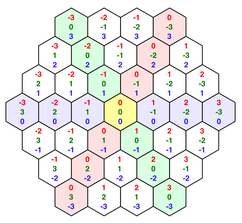
.
.
unitypackage
Work with obstacles
The distances we calculate correspond to the shortest paths from the selected cell to every other cell. We can not find a shorter way. But these paths are guaranteed to be correct if the route does not block anything. Cliffs, water and other obstacles can make us go around. Some cells may not be able to be reached at all.
To find a way around obstacles, we need to use a different approach instead of simply calculating the distance between the coordinates. We can no longer treat each cell separately. We will have to perform a search on the map until we find every cell that can be reached.
Search visualization
Map search is an iterative process. To understand what we are doing, it would be useful to see each stage of the search. We can do this by turning the search algorithm into a quortenine, for which we will need a search space
System.Collections. The refresh rate of 60 iterations per second is small enough for us to see what is happening, and the search on a small map does not take too much time. public void FindDistancesTo (HexCell cell) { StartCoroutine(Search(cell)); } IEnumerator Search (HexCell cell) { WaitForSeconds delay = new WaitForSeconds(1 / 60f); for (int i = 0; i < cells.Length; i++) { yield return delay; cells[i].Distance = cell.coordinates.DistanceTo(cells[i].coordinates); } } We need to make it so that at any time only one search is active. Therefore, before starting a new search, we stop all the Korutins.
public void FindDistancesTo (HexCell cell) { StopAllCoroutines(); StartCoroutine(Search(cell)); } In addition, we need to complete the search when loading a new map.
public void Load (BinaryReader reader, int header) { StopAllCoroutines(); … } Search Breadth (Breadth-First Search)
Even before we start the search, we know that the distance to the selected cell is zero. And, of course, the distance to all its neighbors is 1 if they can be reached. Then we can take a look at one of these neighbors. This cell most likely has its own neighbors, which can be reached and which have not yet calculated the distance. If so, then the distance to these neighbors should be 2. We can repeat this process for all neighbors at a distance of 1. After that we repeat it for all neighbors at a distance of 2. And so on, until we reach all the cells.
That is, first we find all the cells at a distance of 1, then we find everything at a distance of 2, then at a distance of 3, and so on, until we finish. This ensures that we find the smallest distance to each reachable cell. This algorithm is called breadth-first search.
To make it work, we need to know if we have already determined the distance to the cell. Often, cells are placed in a collection called a ready-made or closed set for this. But we can set the distance to the cell value
int.MaxValueto indicate that we have not visited it yet. We need to do this for all the cells right before performing the search. IEnumerator Search (HexCell cell) { for (int i = 0; i < cells.Length; i++) { cells[i].Distance = int.MaxValue; } … } You can also use this to hide all unvisited cells by changing
HexCell.UpdateDistanceLabel. After that we will begin each search on an empty map. void UpdateDistanceLabel () { Text label = uiRect.GetComponent<Text>(); label.text = distance == int.MaxValue ? "" : distance.ToString(); } Next, we need to track the cells that need to be visited, and the order of their visit. Such a collection is often called a border or an open set. We just need to process the cells in the same order in which we met them. You can use a queue for this
Queue, which is part of the namespace System.Collections.Generic. The selected cell will be the first to be placed in this queue, and will have a distance of 0. IEnumerator Search (HexCell cell) { for (int i = 0; i < cells.Length; i++) { cells[i].Distance = int.MaxValue; } WaitForSeconds delay = new WaitForSeconds(1 / 60f); Queue<HexCell> frontier = new Queue<HexCell>(); cell.Distance = 0; frontier.Enqueue(cell); // for (int i = 0; i < cells.Length; i++) { // yield return delay; // cells[i].Distance = // cell.coordinates.DistanceTo(cells[i].coordinates); // } } From this point on, the algorithm performs a loop while there is something in the queue. At each iteration, the frontmost cell is extracted from the queue.
frontier.Enqueue(cell); while (frontier.Count > 0) { yield return delay; HexCell current = frontier.Dequeue(); } Now we have the current cell, which can be at any distance. Next, we need to add all its neighbors to the queue one step further from the selected cell.
while (frontier.Count > 0) { yield return delay; HexCell current = frontier.Dequeue(); for (HexDirection d = HexDirection.NE; d <= HexDirection.NW; d++) { HexCell neighbor = current.GetNeighbor(d); if (neighbor != null) { neighbor.Distance = current.Distance + 1; frontier.Enqueue(neighbor); } } } But we need to add only those cells that have not yet been assigned a distance.
if (neighbor != null && neighbor.Distance == int.MaxValue) { neighbor.Distance = current.Distance + 1; frontier.Enqueue(neighbor); } Search wide.
Avoid water
After making sure that a wider search finds the correct distances on a flat map, we can begin to add obstacles. This can be done by refusing to add cells to the queue if certain conditions are met.
In fact, we are already missing some cells: those that do not exist, and those to which we have already indicated the distance. Let's rewrite the code so that we explicitly skip the neighbors in this case.
for (HexDirection d = HexDirection.NE; d <= HexDirection.NW; d++) { HexCell neighbor = current.GetNeighbor(d); if (neighbor == null || neighbor.Distance != int.MaxValue) { continue; } neighbor.Distance = current.Distance + 1; frontier.Enqueue(neighbor); } Let's also skip all the cells that are under water. This means that when searching for the shortest distances we consider only the movement on the ground.
if (neighbor == null || neighbor.Distance != int.MaxValue) { continue; } if (neighbor.IsUnderwater) { continue; } Distances without moving through the water.
The algorithm still finds the shortest distances, but now it avoids all the water. Therefore, submarine cells never receive distances, as do isolated plots of land. An underwater cell receives a distance only if it is selected.
Avoid cliffs
Also, to determine the possibility of visiting a neighbor, we can use the type of edge. For example, you can make the cliffs block the path. If you allow movement on the slopes, the cells on the other side of the cliff can still be reachable, only along other paths. Therefore, they can be at very different distances.
if (neighbor.IsUnderwater) { continue; } if (current.GetEdgeType(neighbor) == HexEdgeType.Cliff) { continue; } Distances without crossing cliffs.
unitypackage
Relocation costs
We can avoid cells and edges, but these options are binary. It can be imagined that it is easier to move in some directions than in others. In this case, the distance is measured in labor or time.
Fast roads
It will be logical that it is easier and faster to travel along the roads, so let's make the intersection of the edges with the roads less costly. Since we use integer values to set the distance, we will leave the cost of traveling on roads equal to 1, and we will increase the cost of crossing other edges to 10. This is a big difference, which allows us to immediately see if we get the right results.
int distance = current.Distance; if (current.HasRoadThroughEdge(d)) { distance += 1; } else { distance += 10; } neighbor.Distance = distance; Roads with wrong distances.
Border sorting
Unfortunately, it turns out that a wide search cannot work with variable translation costs. He assumes that the cells are added to the border in order of increasing distance, but for us this is irrelevant. We need a priority queue, that is, a queue that sorts itself. There are no standard priority queues, because you cannot program them so that they fit all situations.
We can create our own queue with priority, but we will leave its optimization for the next tutorial. For now, we simply replace the queue with a list that has a method
Sort. List<HexCell> frontier = new List<HexCell>(); cell.Distance = 0; frontier.Add(cell); while (frontier.Count > 0) { yield return delay; HexCell current = frontier[0]; frontier.RemoveAt(0); for (HexDirection d = HexDirection.NE; d <= HexDirection.NW; d++) { … neighbor.Distance = distance; frontier.Add(neighbor); } } Unless it is impossible to use ListPool <HexCell>?
, , . , , .
To make the border true, we need to sort it after adding a cell to it. In fact, we can postpone sorting until all the neighbors of the cell are added, but, I repeat, we are not interested in optimizations yet.
We want to sort the cells by distance. To do this, we need to call the list sorting method with reference to the method that performs this comparison.
frontier.Add(neighbor); frontier.Sort((x, y) => x.Distance.CompareTo(y.Distance)); How does this Sort method work?
. , . .
frontier.Sort(CompareDistances); … static int CompareDistances (HexCell x, HexCell y) { return x.Distance.CompareTo(y.Distance); } The sorted border is still not valid.
Border update
After the border began to be sorted, we began to get better results, but errors still exist. This is because when a cell is added to the boundary, we do not necessarily find the shortest distance to that cell. This means that now we can no longer miss neighbors who have already been assigned a distance. Instead, we need to check if we have found a shorter way. If so, then we need to change the distance to the neighbor, instead of adding it to the border.
HexCell neighbor = current.GetNeighbor(d); if (neighbor == null) { continue; } if (neighbor.IsUnderwater) { continue; } if (current.GetEdgeType(neighbor) == HexEdgeType.Cliff) { continue; } int distance = current.Distance; if (current.HasRoadThroughEdge(d)) { distance += 1; } else { distance += 10; } if (neighbor.Distance == int.MaxValue) { neighbor.Distance = distance; frontier.Add(neighbor); } else if (distance < neighbor.Distance) { neighbor.Distance = distance; } frontier.Sort((x, y) => x.Distance.CompareTo(y.Distance)); The correct distances.
Now, when we get the right distances, we start to consider the cost of moving. You may notice that the distances to some cells are initially too large, but are corrected when they are removed from the border. This approach is called the Dijkstra algorithm, it is named after Edsger Dijkstra, who first invented it.
Slopes
We do not want to limit ourselves to differing costs only for roads. For example, you can reduce the cost of crossing flat edges without roads to 5, leaving 10 for slopes without roads.
HexEdgeType edgeType = current.GetEdgeType(neighbor); if (edgeType == HexEdgeType.Cliff) { continue; } int distance = current.Distance; if (current.HasRoadThroughEdge(d)) { distance += 1; } else { distance += edgeType == HexEdgeType.Flat ? 5 : 10; } To overcome the slopes need to make more work, and the roads are always fast.
Objects of relief
We can add costs in the presence of terrain objects. For example, in many games in the woods to move more difficult. In this case, we simply add to the distance all levels of objects. And here again the road accelerates everything.
if (current.HasRoadThroughEdge(d)) { distance += 1; } else { distance += edgeType == HexEdgeType.Flat ? 5 : 10; distance += neighbor.UrbanLevel + neighbor.FarmLevel + neighbor.PlantLevel; } Objects slow down if there is no road.
Walls
Finally, let's take the walls into account. Walls should block movement if the road does not pass through them.
if (current.HasRoadThroughEdge(d)) { distance += 1; } else if (current.Walled != neighbor.Walled) { continue; } else { distance += edgeType == HexEdgeType.Flat ? 5 : 10; distance += neighbor.UrbanLevel + neighbor.FarmLevel + neighbor.PlantLevel; } The walls do not let us through, you need to look for the gate.
unitypackage
Source: https://habr.com/ru/post/425919/
All Articles