Educational program in chemistry: acid reversing of microcircuits (how to expose a crystal of a microcircuit for its subsequent photographing)
Introduction
If you are already engaged in etching and photographing microcircuits, there is little you can learn from this article. However, if you want to take a picture of the chip, but do not know where to start, then this article is definitely for you. In addition, keep in mind that the first steps in mastering this fascinating procedure will probably hurt you a little.
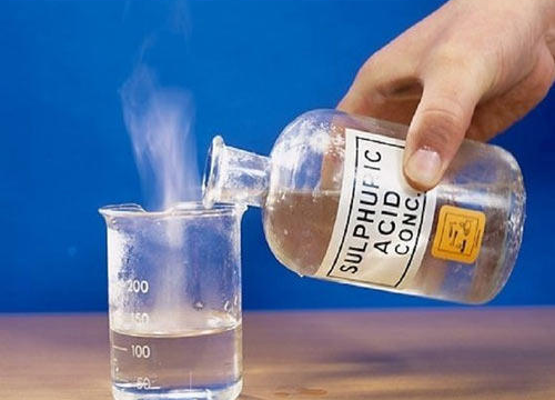
Please take extreme caution, then it will hurt you though it will, but not much. Also, if you have at least a tiny inclination towards common sense, conduct this procedure in a specially equipped chemical laboratory, under the supervision of experienced specialists; and do not become a victim of your arrogance, thinking that after reading this educational program, you can immediately carry out this procedure yourself. Moreover, if you don’t turn to Google and don’t know what to pour (acid into water or acid) and don’t know what this ignorance is fraught with for you, please stop reading this educational program and first sign up for courses Someone local technical school, where there is a good chemical laboratory.
Chemical equipment
If we proceed from the absolutely necessary minimum, then you need highly concentrated nitric acid (HNO3) and sulfuric acid (H2SO4). The legality of their acquisition varies from country to country. If you live in a country in which the government takes special care of the environment, you will probably need a different method (I heard that the Germans are achieving good results with rosin). In addition to these two acids, you also need isopropyl alcohol and acetone, as solvents, for stripping. In addition to chemicals, you will also need some glassware. Fortunately, the procedure is quite simple, so all you need is a few test tubes, a few glasses and a ring stand with a burette clamp.
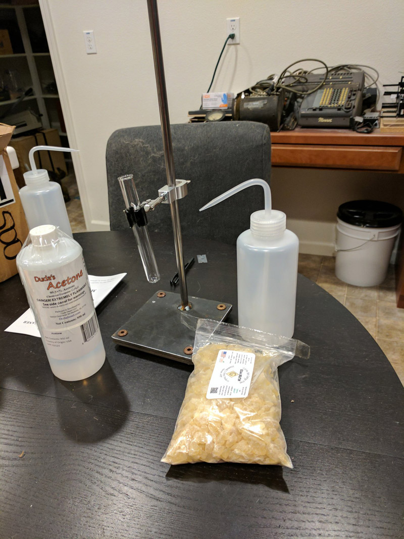
- When purchasing used clamps, keep in mind that the metal should not come into contact with the glass walls of the test tubes; on the clamps, already used, there may be no gasket (rubber or fabric) that protects from scratches.
- Acids with which you have to work, can bite into the metal, so stock up with acid-resistant tweezers. As practice shows, tweezers tend to get lost or bend, so buy a dozen at once to solve this problem once and for all.
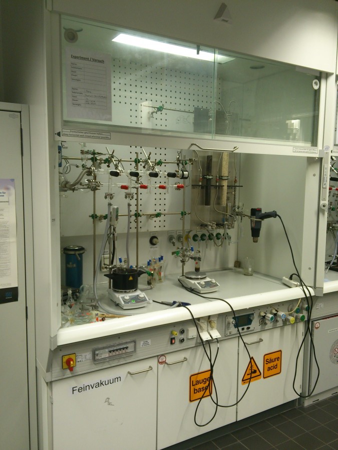
- Since acid fumes, especially nitric acid fumes, are very harmful, you will need a fume hood to properly “curb” the acid gas that will boil out of the tube when you start to heat it.
- As a convenient indicator of the level to which acid pairs have risen, you can use thermal paper from air and railway tickets. When in contact with acid fumes, thermal paper turns black or red. The ticket suspended above the tube will give you a visual signal when acid vapors will erupt excessively.
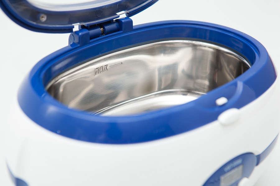
- To clean the surface of the chip with a solvent, you can basically do with a toothbrush, but it is preferable and safer to use ultrasonic baths. Cheap ultrasonic baths can be found with jewelers, - they work pretty well. But be careful that your cleaning solvents do not dissolve the plastic parts of these ultrasonic baths.
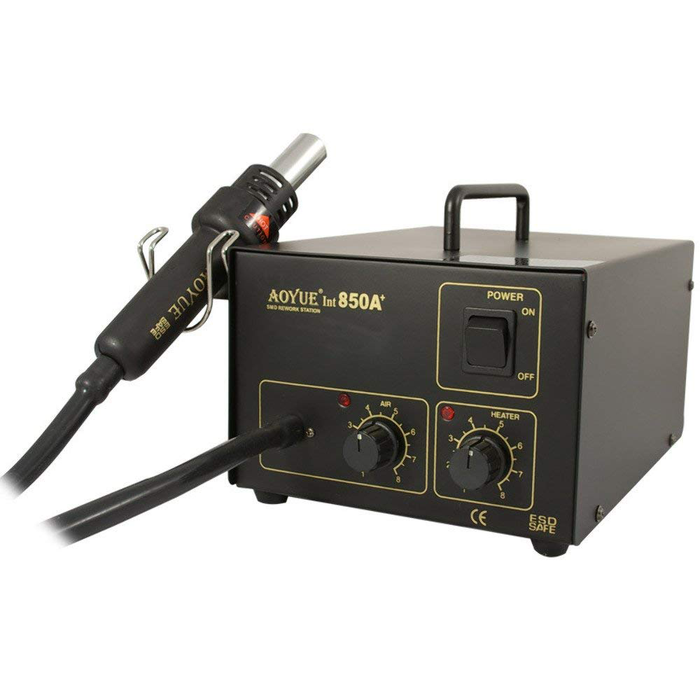
- Finally, you will need a regulated heat source. You probably already joyfully stretched out your hand over the Bunsen gas burner ... But it is absolutely not suitable for our procedure. Instead, it is better to use an inexpensive thermoair soldering station designed to work with SMD: surface-mounted printed circuit boards. For example Aoyue 850A. By rotating the airflow regulator of the heat gun near the maximum and slowly raising its temperature, you can heat the tube to the desired temperature, and then maintain it.
Chemical procedure
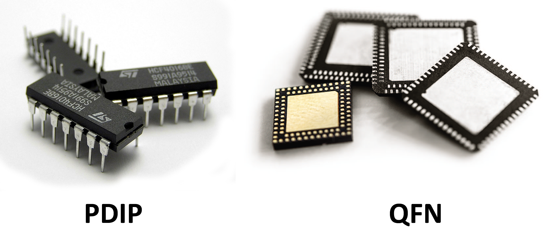
The form factor of your sample chip should be minimal, of all those that are commercially available. For example, Texas Instruments MSP430F2012 is available in two form factors: PDIP (Plastic Dual Inline Package; Plastic case with double-row pin layout) and QFN (Quad Flat No-leads; Square case, without legs). Although the procedure described is applicable to all form factors, QFN is preferable. Because it is much smaller and there is less plastic on it, which in any case will have to be etched; this means that less nitric acid is needed to etch the QFN sample.
- Start by connecting the burette clamp to the ring stand. And point the soldering station nozzle, just below the bottom of the tube. But do not turn on the heat yet.
- Place the microchip in a tube with enough nitric acid to completely hide under the acid. To taste, you can add a drop of sulfuric acid (but do not overdo it, otherwise it will eat not only plastic, but also wire compounds). For reasons of self-preservation, you will rather quickly learn how to do this procedure in that short period of time while the glass is still cold; as well as you very quickly, and quite painfully find out that, oddly enough, the cold glass looks exactly the same as hot.
- Place the tube in the burette clamp. The tube should be slightly tilted. The lower side is closer to you, the upper one farther away from you, so that explosive eruptions of boiling acid, which sometimes occur, fly by on your side.
- So you have an acid coated chip. Now set up the soldering station for a high air flow rate of the heat gun and for low heat. Slowly raise the temperature while observing a well-lit column of acid fumes. The idea is to find a temperature at which the acid boils very intensively, but at the same time the column of acid vapors above it stays below the edges of the tube and does not fly out.
- A laser pointer beam directed into the tube will show the exact height of this column, since acid fumes, unlike clean air, will be highlighted by a laser beam.
- Overheating of the tubes will lead to the fact that the acid fumes will fly out - filling out a fume hood or a laboratory. In the latter case, all the iron in the room will begin to rust, your lungs will burn, and among other things the fire alarm will work. Do not do this.
- As the microcircuit boils in nitric acid, its body will crumble into pieces. This chipping is necessary to continue until the acid begins to corrode the crystal chip itself, or until the acid loses its corrosive ability.
- You may notice that the color of the acid solution changes. HNO3 turns green or blue after dissolving copper, and this indicates that its ability to corrode plastic has decreased significantly. After the acid has been used up, allow the tube to cool and then pour its contents into an empty glass.
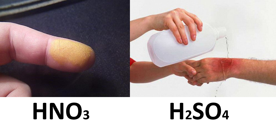
- At the moment, the acid is not strong enough to corrode the body of the chip - but still strong enough to eat away your skin. HNO3 burns do not hurt at first, and they are also bright. Therefore, you can not even notice them immediately, with the exception of yellowed skin, which will gradually exfoliate during the week (or so). Sometimes you can feel it as an itch rather than a burn. Therefore, if some stain on your hand began to itch, run like a scalded to the sink. H2SO4 burns more intensely. When it hits the skin, there is a sharp burning pain, and the skin becomes covered with a red rash.
- So, now that your knowledge extends a little further than understanding the fact that you should not stick your fingers in test tubes with acid, use tweezers to carefully remove the crystal chip from the acid, and lower it into another glass - with acetone. This glass (glass of acetone) is then sent to an ultrasonic bath for several minutes.
- At this stage, the crystal is usually almost completely naked. Only minor bits of dirt are observed. However, if the microcircuit case is large, then one portion of nitric acid may not be enough (after the first time, the crystal still remains covered). To achieve the best result, the procedure with HNO3 should be repeated until there is very little dirt on the chip. Then, before the photo session, the crystal should take a bath in H2SO4, where the remaining crumbs of dirt will be cleaned from it.
- These two acids are very different in their behavior. You will find that taking a bath with H2SO4, your microchip behaves completely differently than in a bath with HNO3. H2SO4 has a much higher boiling point than HNO3, but at the same time it well eats away the body of the chip even below its boiling point. You will also find that in H2SO4 the case of the microcircuit is neither painted, but dissolved, and the acid acquires an ink-black color, and through it, because of this, it is no longer possible to discern the crystal of the microcircuit in order to understand whether it is time to pull it out or not.
- After swimming in H2SO4, hold the crystal for several minutes in an ultrasonic bath. Everything, now he is ready for a photo session.
Photography Equipment
Now that you have a naked crystal, you can take a picture of it. This will require a metallographic microscope - i.e. the one that highlights the picture with a reflecting light, and not passing.
- To photograph the crystal chip, you can either purchase a special camera for the microscope, or use a digital SLR camera. Both options have their advantages, but it is worth noting that “special cameras for the microscope” often turn out to be the most primitive budget options of webcams, with uncomfortable software that works only under Windows. Therefore, it is better to use a digital SLR camera.
Photography procedure. Whichever camera you use, you will not be able to take a picture of the entire chip with one shot. To get an image of the entire microcircuit, you will have to take a picture of it in parts, and then sew these parts into a single image. This can be done using the software designed for working with panoramic images. - To ensure the best result, each image fragment should overlap by about a third, with images before and after it, as well as with adjacent lines.
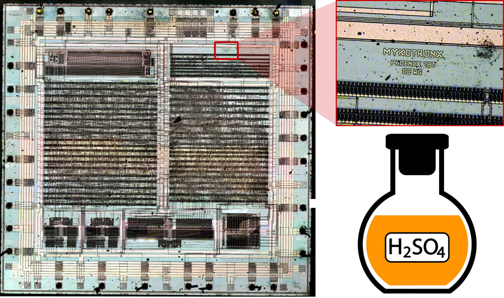
- After you capture the entire microchip, upload the resulting images to Hugin, on a computer with a sufficient amount of RAM. Hugin is a utility for stitching panoramic images. She, among other things, is good because she can correct the mistakes made when photographing, if there are not too many of them. Hugin will do everything possible to align all the fragments of your image. At the exit, it produces either an almost perfect pattern, or an ugly confusion. If this confusion occurs due to a minor error, you can make the necessary adjustments through Hugin. However, in the case of serious errors, such as insufficient overlap or poor focus, a repeated photo session will be needed for the chip on the chip. The following figure shows a full photograph of the crystal (in reduced resolution) of the Clipper chip. The photo was built using the Hugin utility.
')
Source: https://habr.com/ru/post/425715/
All Articles