DevBoy: make a signal generator
Hello friends!
In previous articles I talked about my project and its program part . In this article I will tell how to make a simple signal generator for 4 channels - two analog channels and two PWM channels.
The STM32F415RG microcontroller incorporates a 12-bit DAC (digital-to-analog) converter for two independent channels, which allows you to generate different signals. You can directly load data into the converter registers, but this is not very suitable for generating signals. The best solution is to use an array in which to generate a single wave of the signal, and then start the DAC with a trigger from the timer and DMA. By changing the frequency of the timer, you can change the frequency of the generated signal.
')
" Classic " waveforms include: sine wave, square wave, triangular and sawtooth wave.

In the function you need to pass a pointer to the beginning of the array, the size of the array, the maximum value and the desired waveform. After the call, the array will be filled with samples for one wave of the desired shape and you can start a timer to periodically load the new value into the DAC.
The DAC in this microcontroller has a limitation: the typical settling time (the time from loading a new value into the DAC and its appearance at the output ) is 3 ms. But not everything is so simple - this time is the maximum, i.e. change from minimum to maximum and vice versa. When you try to bring out the meander, these littered fronts are very clearly visible:
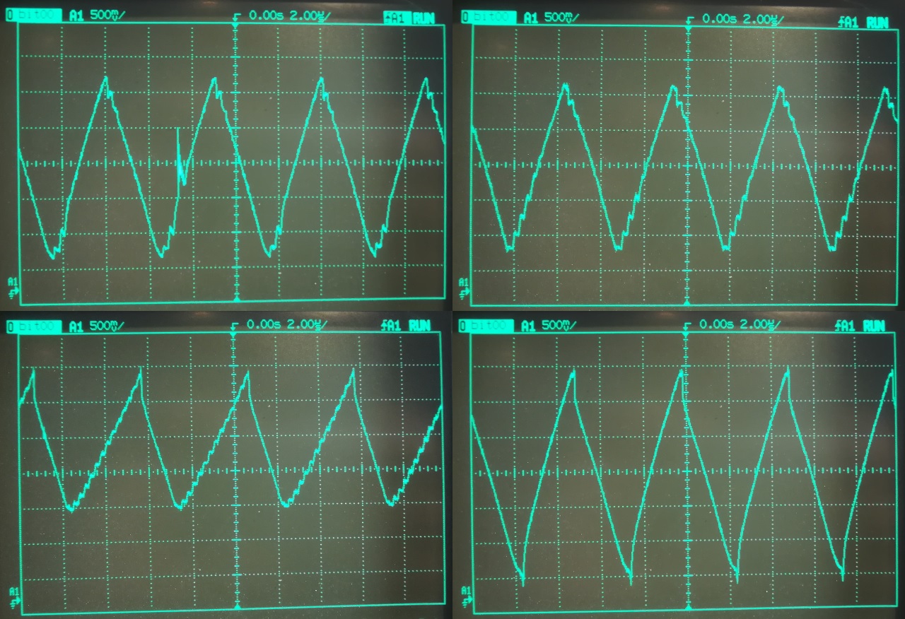
If, however, to output a sine wave, the collapse of the fronts is not so noticeable due to the waveform. However, if you increase the frequency of the sinusoidal signal becomes triangular, and with further increase the amplitude of the signal decreases.
Generation at 1 KHz ( 90% amplitude ):
Generation at 10 KHz ( 90% amplitude ):
Generation at 100 KHz ( 90% amplitude ):

Steps are already visible - because new data is loaded into the DAC at 4 MHz.
In addition, the rear front of the ramp is littered and from the bottom the signal does not reach the value to which it should. This is because the signal does not reach the specified low level, and the software loads already new values.
Generation at 200 KHz ( 90% amplitude ):
Here you can see how all the waves turned into a triangle.
With digital channels, everything is much simpler - in almost any microcontroller there are timers that allow you to output the PWM signal to the microcontroller pins. It is best to use a 32-bit timer - in this case you do not need to recalculate the predecessor of the timer, it is enough to load the period into one register and load the required ratio in the other register.
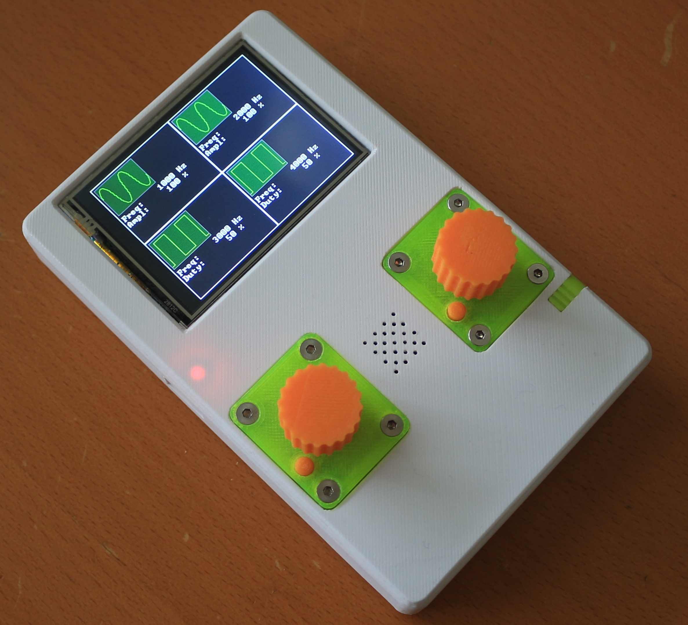
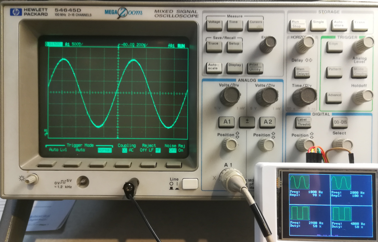
It was decided to organize the user interface into four rectangles, each has a picture of the output signal, frequency and amplitude / duty cycle. For the currently selected channel text data is displayed in white font, for the rest - in gray.
Management was decided to do on the encoders: the left is responsible for the frequency and the current selected channel ( changes when you press the button ), the right is responsible for the amplitude / duty cycle and waveform ( changes when you press the button ).
In addition, support for the touch screen is implemented - when you click on an inactive channel, it becomes active, when you click on an active channel, the waveform changes.
Of course, DevCore is used to implement all of this. The code for initializing the user interface and updating the data on the screen looks like this:
Interestingly implemented processing of pressing the button ( represents a rectangle on top of which the remaining elements are drawn ). If you looked at the code, you should have noticed such a thing: ch_dsc [i] .box. SetCallback (& Callback, this, nullptr, i); called in a loop. This is the task of the callback function that will be called when the button is pressed. The following functions are passed to the function: the address of the static function of the static class function, the this pointer, and two user parameters that will be passed to the callback function - a pointer ( not used in this case - nullptr is passed ) and a number (the channel number is transmitted ).
From university, I remember the postulate: " Static functions do not have access to non-static class members ." So this is not true . Since a static function is a member of a class, it has access to all members of the class if it has a link / pointer to this class. Now take a look at the callback function:
In the very first line of this function, " magic " occurs, after which you can access any members of the class, including private ones.
By the way, the call to this function occurs in another task ( drawing the screen ), so inside this function you need to take care of synchronization. In this unpretentious project " couple of evenings " I did not do this, because in this particular case it is not essential.
Generator source code uploaded to GitHub: https://github.com/nickshl/WaveformGenerator
DevCore is now allocated in a separate repository and is included as a submodule.
Well, why do I need a signal generator, will be in the next ( or one of the following ) articles.
In previous articles I talked about my project and its program part . In this article I will tell how to make a simple signal generator for 4 channels - two analog channels and two PWM channels.
Analog channels
The STM32F415RG microcontroller incorporates a 12-bit DAC (digital-to-analog) converter for two independent channels, which allows you to generate different signals. You can directly load data into the converter registers, but this is not very suitable for generating signals. The best solution is to use an array in which to generate a single wave of the signal, and then start the DAC with a trigger from the timer and DMA. By changing the frequency of the timer, you can change the frequency of the generated signal.
')
" Classic " waveforms include: sine wave, square wave, triangular and sawtooth wave.
The function of generating these waves in the buffer is as follows
// ***************************************************************************** // *** GenerateWave ******************************************************** // ***************************************************************************** Result Application::GenerateWave(uint16_t* dac_data, uint32_t dac_data_cnt, uint8_t duty, WaveformType waveform) { Result result; uint32_t max_val = (DAC_MAX_VAL * duty) / 100U; uint32_t shift = (DAC_MAX_VAL - max_val) / 2U; switch(waveform) { case WAVEFORM_SINE: for(uint32_t i = 0U; i < dac_data_cnt; i++) { dac_data[i] = (uint16_t)((sin((2.0F * i * PI) / (dac_data_cnt + 1)) + 1.0F) * max_val) >> 1U; dac_data[i] += shift; } break; case WAVEFORM_TRIANGLE: for(uint32_t i = 0U; i < dac_data_cnt; i++) { if(i <= dac_data_cnt / 2U) { dac_data[i] = (max_val * i) / (dac_data_cnt / 2U); } else { dac_data[i] = (max_val * (dac_data_cnt - i)) / (dac_data_cnt / 2U); } dac_data[i] += shift; } break; case WAVEFORM_SAWTOOTH: for(uint32_t i = 0U; i < dac_data_cnt; i++) { dac_data[i] = (max_val * i) / (dac_data_cnt - 1U); dac_data[i] += shift; } break; case WAVEFORM_SQUARE: for(uint32_t i = 0U; i < dac_data_cnt; i++) { dac_data[i] = (i < dac_data_cnt / 2U) ? max_val : 0x000; dac_data[i] += shift; } break; default: result = Result::ERR_BAD_PARAMETER; break; } return result; } In the function you need to pass a pointer to the beginning of the array, the size of the array, the maximum value and the desired waveform. After the call, the array will be filled with samples for one wave of the desired shape and you can start a timer to periodically load the new value into the DAC.
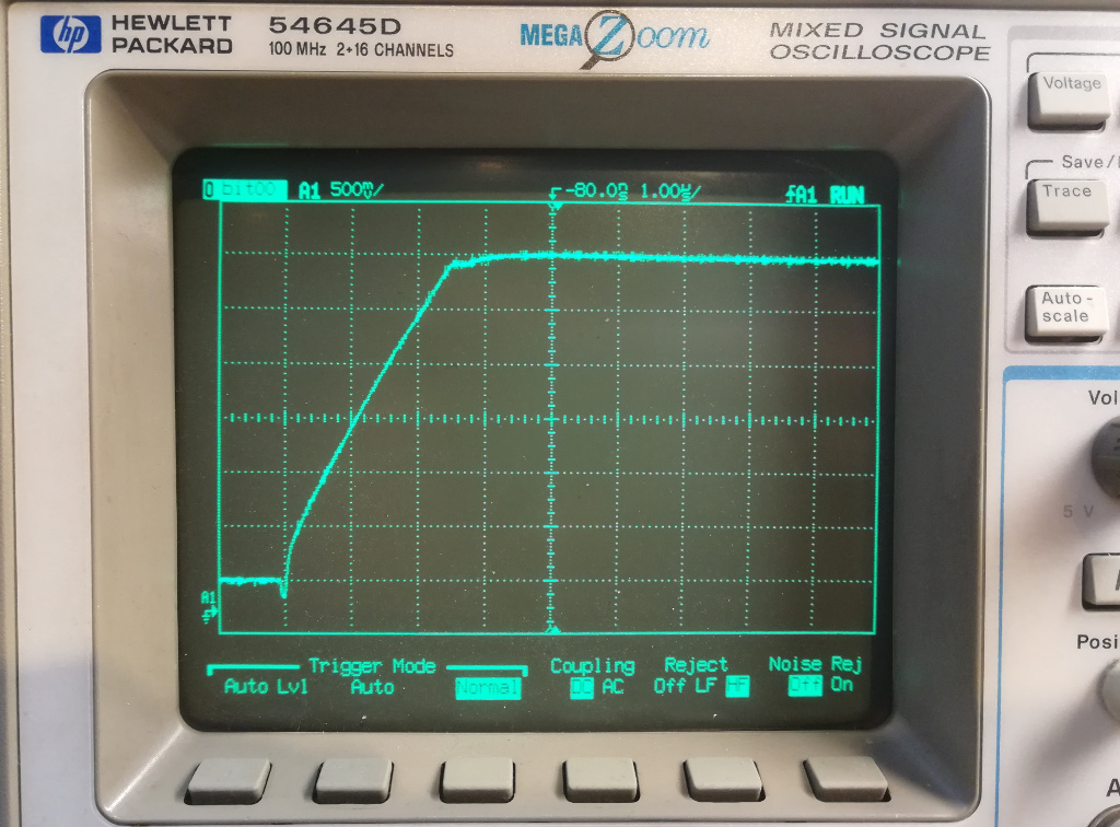
The DAC in this microcontroller has a limitation: the typical settling time (the time from loading a new value into the DAC and its appearance at the output ) is 3 ms. But not everything is so simple - this time is the maximum, i.e. change from minimum to maximum and vice versa. When you try to bring out the meander, these littered fronts are very clearly visible:
If, however, to output a sine wave, the collapse of the fronts is not so noticeable due to the waveform. However, if you increase the frequency of the sinusoidal signal becomes triangular, and with further increase the amplitude of the signal decreases.
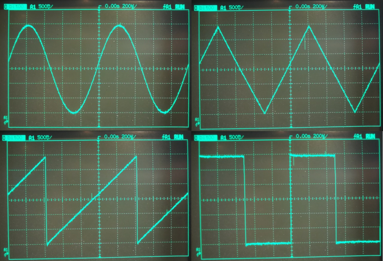
Generation at 1 KHz ( 90% amplitude ):
Generation at 10 KHz ( 90% amplitude ):
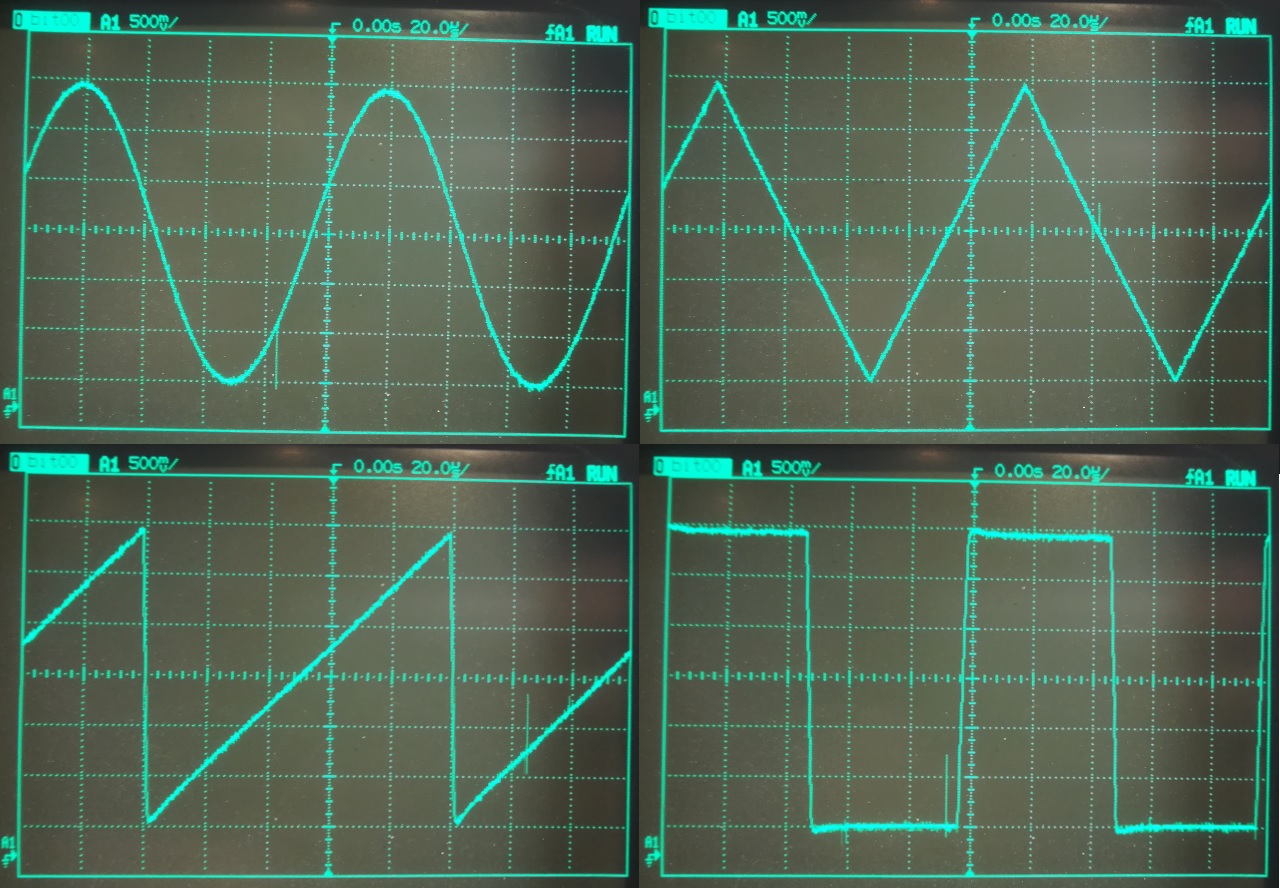
Generation at 100 KHz ( 90% amplitude ):
Steps are already visible - because new data is loaded into the DAC at 4 MHz.
In addition, the rear front of the ramp is littered and from the bottom the signal does not reach the value to which it should. This is because the signal does not reach the specified low level, and the software loads already new values.
Generation at 200 KHz ( 90% amplitude ):
Here you can see how all the waves turned into a triangle.
Digital channels
With digital channels, everything is much simpler - in almost any microcontroller there are timers that allow you to output the PWM signal to the microcontroller pins. It is best to use a 32-bit timer - in this case you do not need to recalculate the predecessor of the timer, it is enough to load the period into one register and load the required ratio in the other register.
User interface
It was decided to organize the user interface into four rectangles, each has a picture of the output signal, frequency and amplitude / duty cycle. For the currently selected channel text data is displayed in white font, for the rest - in gray.
Management was decided to do on the encoders: the left is responsible for the frequency and the current selected channel ( changes when you press the button ), the right is responsible for the amplitude / duty cycle and waveform ( changes when you press the button ).
In addition, support for the touch screen is implemented - when you click on an inactive channel, it becomes active, when you click on an active channel, the waveform changes.
Of course, DevCore is used to implement all of this. The code for initializing the user interface and updating the data on the screen looks like this:
A structure containing all UI objects
// ************************************************************************* // *** Structure for describes all visual elements for the channel ***** // ************************************************************************* struct ChannelDescriptionType { // UI data UiButton box; Image img; String freq_str; String duty_str; char freq_str_data[64] = {0}; char duty_str_data[64] = {0}; // Generator data ... }; // Visual channel descriptions ChannelDescriptionType ch_dsc[CHANNEL_CNT]; UI Initialization Code
// Create and show UI int32_t half_scr_w = display_drv.GetScreenW() / 2; int32_t half_scr_h = display_drv.GetScreenH() / 2; for(uint32_t i = 0U; i < CHANNEL_CNT; i++) { // Generator data ... // UI data int32_t start_pos_x = half_scr_w * (i%2); int32_t start_pos_y = half_scr_h * (i/2); ch_dsc[i].box.SetParams(nullptr, start_pos_x, start_pos_y, half_scr_w, half_scr_h, true); ch_dsc[i].box.SetCallback(&Callback, this, nullptr, i); ch_dsc[i].freq_str.SetParams(ch_dsc[i].freq_str_data, start_pos_x + 4, start_pos_y + 64, COLOR_LIGHTGREY, String::FONT_8x12); ch_dsc[i].duty_str.SetParams(ch_dsc[i].duty_str_data, start_pos_x + 4, start_pos_y + 64 + 12, COLOR_LIGHTGREY, String::FONT_8x12); ch_dsc[i].img.SetImage(waveforms[ch_dsc[i].waveform]); ch_dsc[i].img.Move(start_pos_x + 4, start_pos_y + 4); ch_dsc[i].box.Show(1); ch_dsc[i].img.Show(2); ch_dsc[i].freq_str.Show(3); ch_dsc[i].duty_str.Show(3); } Refresh code on screen
for(uint32_t i = 0U; i < CHANNEL_CNT; i++) { ch_dsc[i].img.SetImage(waveforms[ch_dsc[i].waveform]); snprintf(ch_dsc[i].freq_str_data, NumberOf(ch_dsc[i].freq_str_data), "Freq: %7lu Hz", ch_dsc[i].frequency); if(IsAnalogChannel(i)) snprintf(ch_dsc[i].duty_str_data, NumberOf(ch_dsc[i].duty_str_data), "Ampl: %7d %%", ch_dsc[i].duty); else snprintf(ch_dsc[i].duty_str_data, NumberOf(ch_dsc[i].duty_str_data), "Duty: %7d %%", ch_dsc[i].duty); // Set gray color to all channels ch_dsc[i].freq_str.SetColor(COLOR_LIGHTGREY); ch_dsc[i].duty_str.SetColor(COLOR_LIGHTGREY); } // Set white color to selected channel ch_dsc[channel].freq_str.SetColor(COLOR_WHITE); ch_dsc[channel].duty_str.SetColor(COLOR_WHITE); // Update display display_drv.UpdateDisplay(); Interestingly implemented processing of pressing the button ( represents a rectangle on top of which the remaining elements are drawn ). If you looked at the code, you should have noticed such a thing: ch_dsc [i] .box. SetCallback (& Callback, this, nullptr, i); called in a loop. This is the task of the callback function that will be called when the button is pressed. The following functions are passed to the function: the address of the static function of the static class function, the this pointer, and two user parameters that will be passed to the callback function - a pointer ( not used in this case - nullptr is passed ) and a number (the channel number is transmitted ).
From university, I remember the postulate: " Static functions do not have access to non-static class members ." So this is not true . Since a static function is a member of a class, it has access to all members of the class if it has a link / pointer to this class. Now take a look at the callback function:
// ***************************************************************************** // *** Callback for the buttons ********************************************* // ***************************************************************************** void Application::Callback(void* ptr, void* param_ptr, uint32_t param) { Application& app = *((Application*)ptr); ChannelType channel = app.channel; if(channel == param) { // Second click - change wave type ... } else { app.channel = (ChannelType)param; } app.update = true; } In the very first line of this function, " magic " occurs, after which you can access any members of the class, including private ones.
By the way, the call to this function occurs in another task ( drawing the screen ), so inside this function you need to take care of synchronization. In this unpretentious project " couple of evenings " I did not do this, because in this particular case it is not essential.
Generator source code uploaded to GitHub: https://github.com/nickshl/WaveformGenerator
DevCore is now allocated in a separate repository and is included as a submodule.
Well, why do I need a signal generator, will be in the next ( or one of the following ) articles.
Source: https://habr.com/ru/post/425409/
All Articles