A guide to bringing a “clone” to the clone of the popular Chinese mini-router Hame A15, aka “unbranded A5-V11”
If I saw farther than others, it is because I stood on the shoulders of giants.
I.Newton
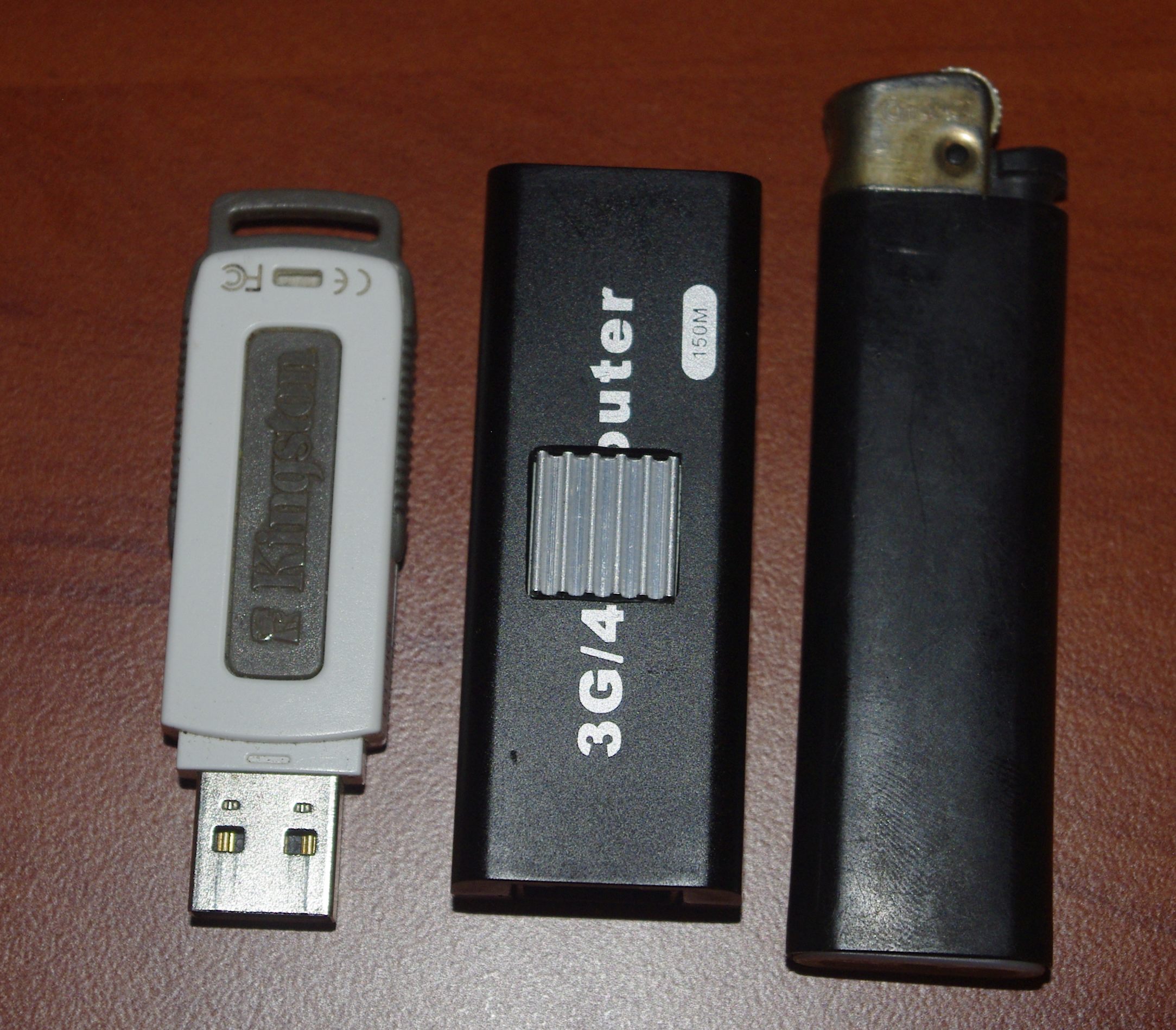
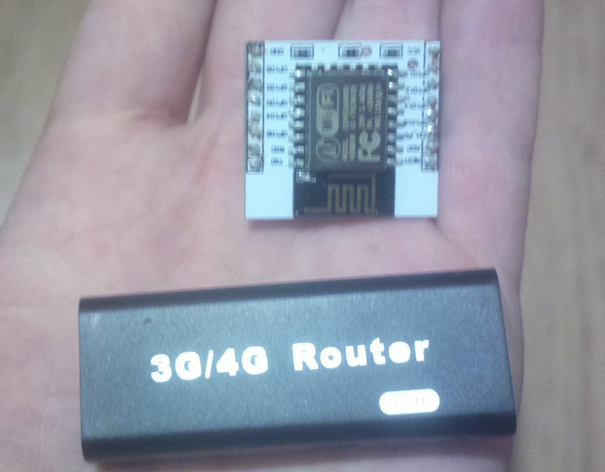
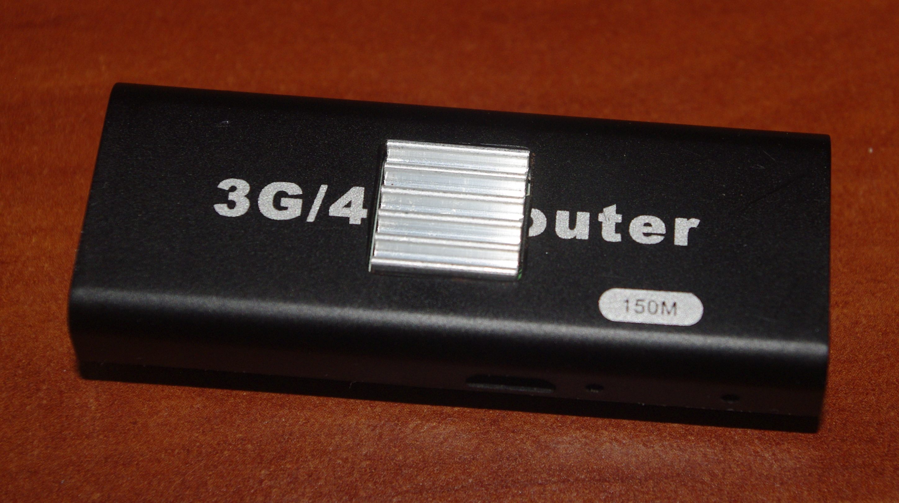
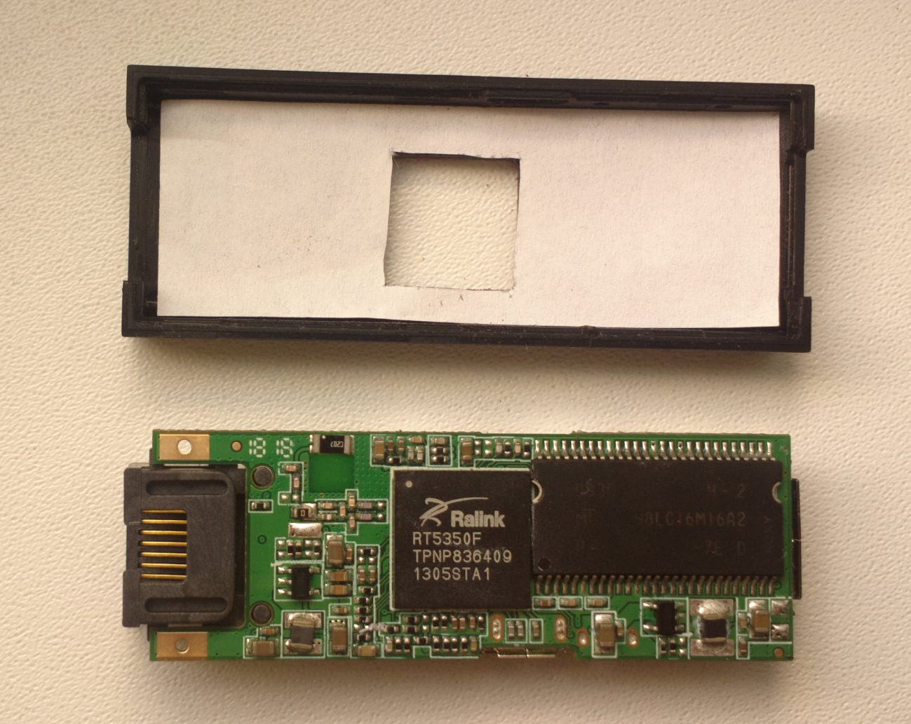
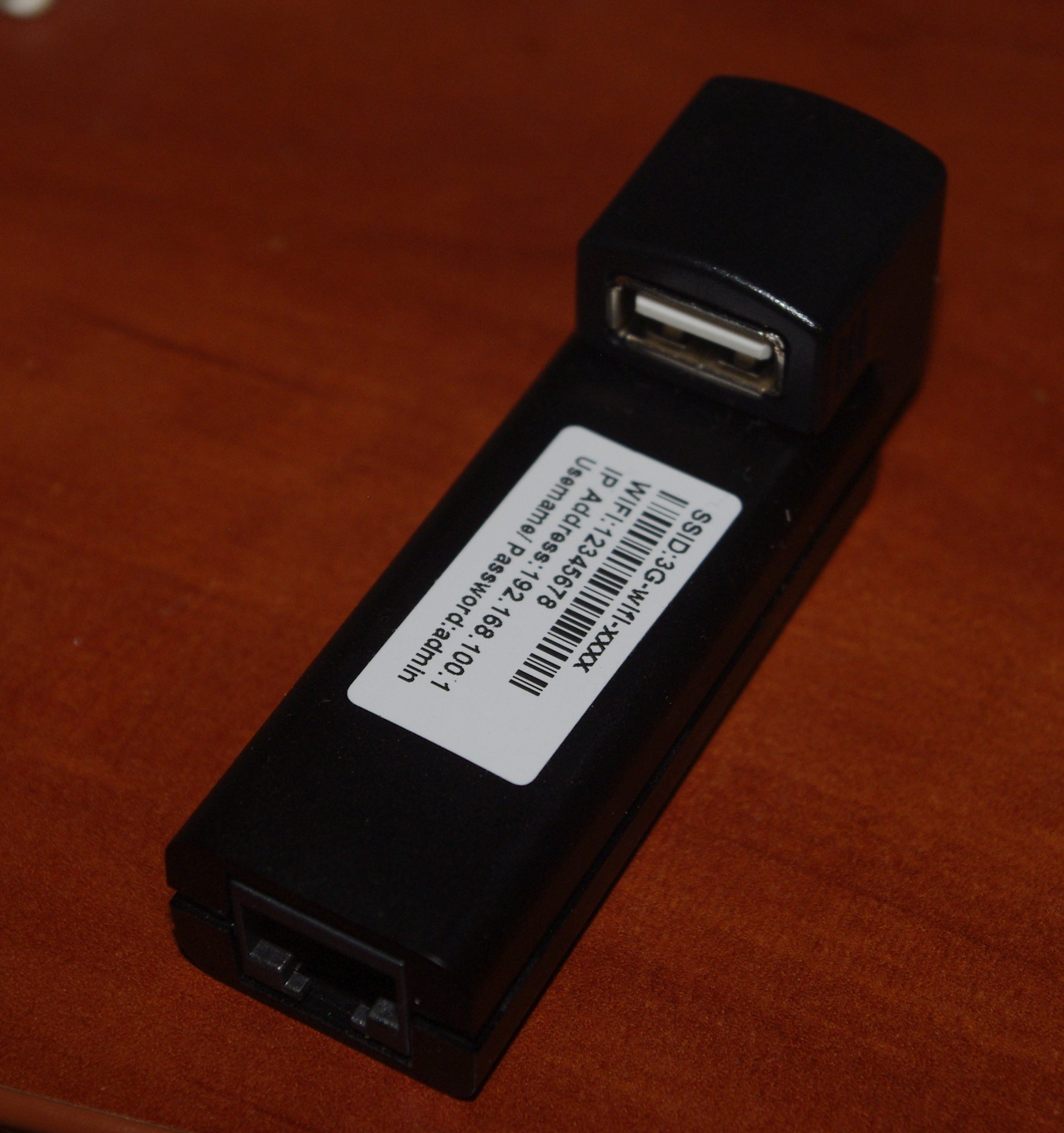
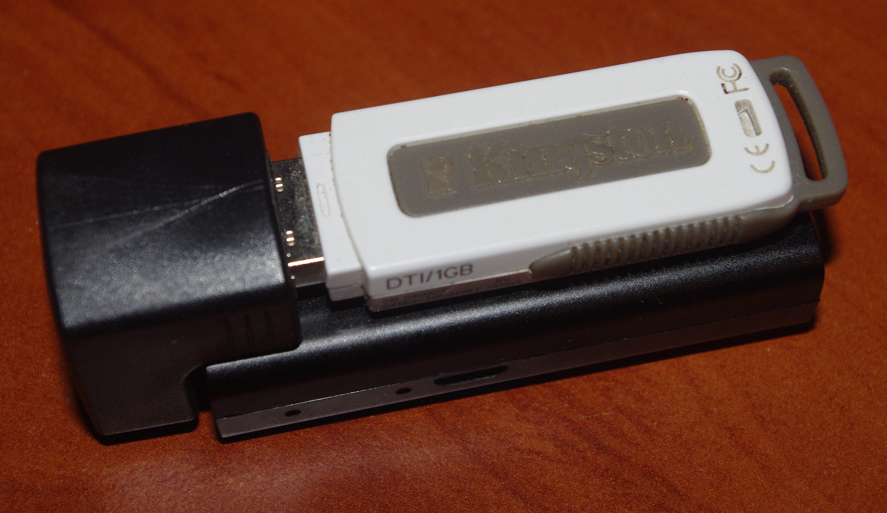
I think many people know the small Chinese Hame A15 router (it, or rather its massive copies, with improved TTX compared to the original, is equally good at using the keywords 3g / 4g router on both ebay and aliexpress ). Today I wanted to tell how I brought to mind the $ 6.5 router and spent $ 20 on it. What for? And for about the same reason why bracelets are woven from beads - to train a micromotorica and to implant a sight (the body of the components is mostly 0402 :) Mostly for sporting interest, although it is also important that this router is today my favorite base for various projects (even despite the difficulty of accessing GPIO), instead of “popular” NEXX WT3020F, TP-Link TL-MR3020, TP-Link TL-WR703N and others like them. The reason for this in the first place is its size and shape of the printed circuit board, convenient for embedding anywhere (in the photo you can estimate the size). Further, in order to avoid confusion of terminology, I will call the device shown below as it is called by wiki openwrt - A5-V11 .
The heart of this device is the SoC Ralink RT5350F with a frequency of 360 MHz, the board has a full USB host, 4 MB of flash memory and 32 MB of RAM SDRAM with a frequency of 166 MHz (which is by the way strange, because even the ancient D-link DIR-320 on board had a faster DDR). Some clone clones have 16 MB of memory and are not suitable without increasing RAM for the manipulations described in the article.
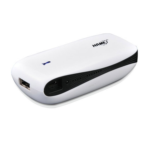
As usual, the picture below shows the original router Hame A15.
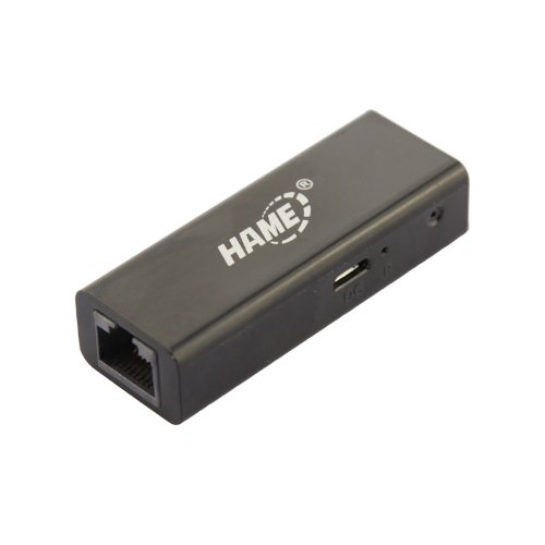
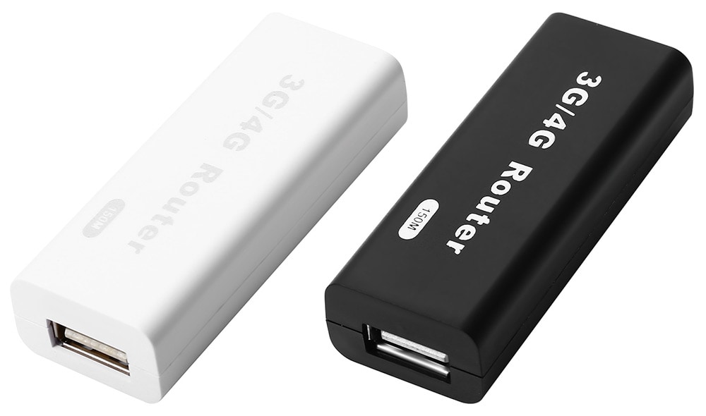
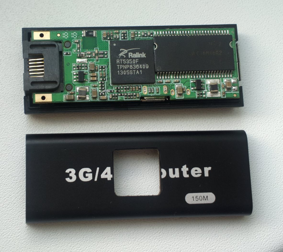
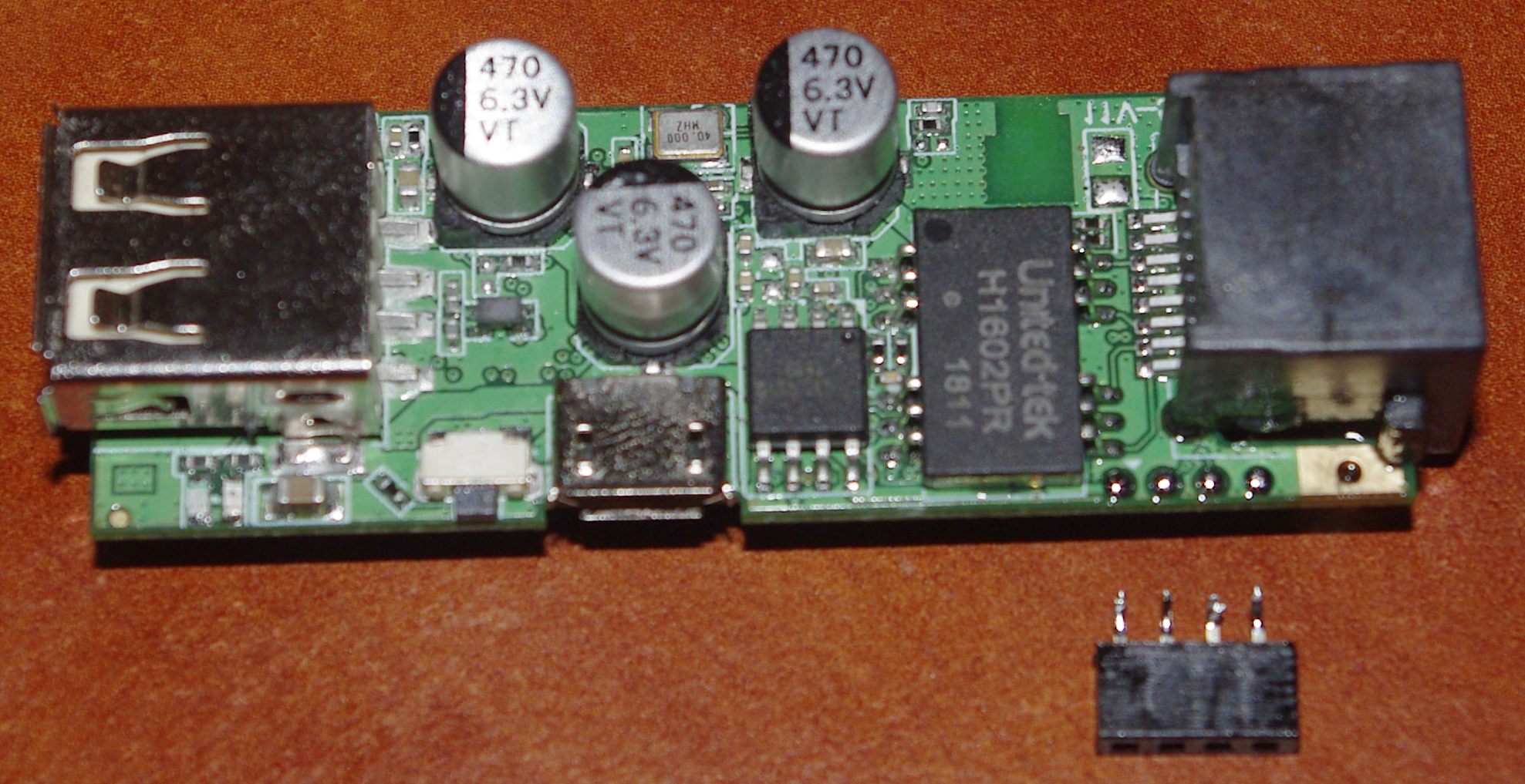
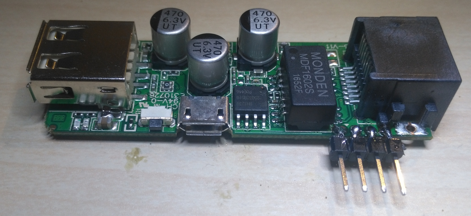
And this is how its improved Chinese copy looks like (at the end of the article you can see another copy of the copy, but 10 times more expensive :).
The interiors of the firmware were already covered in the Habré, so I will not dwell on the features of the markup. Details of the problems and solutions are described on w3bsit3-dns.com . There is a lot of information, but it is incredibly scattered. I hope in this article to collect the key points, based on the experience of the guys, "the giants of the router" :)
The answer to the question "why does this (router) need an inexperienced user" will quote the user ded1971 :
General consumer properties - universal compact 3G-WiFi-router. It is convenient to take on trips, connect a 3G / 4G modem, organize your WiFi network, or use as a repeater to enhance WiFi, connect the Internet to a smart TV if there is no built-in WiFi. In general, a lot of useful features for ridiculous money.
Part one, preparatory
While the router went by mail, it was time to study the reviews of happy owners. The main problems faced by most are problems of overheating of the router (and, accordingly, “chip dump”) and power instability, when the router cannot start for a long time (“indicator” - two LEDs are dimly lit, it is impossible to connect to the device via Ethernet).
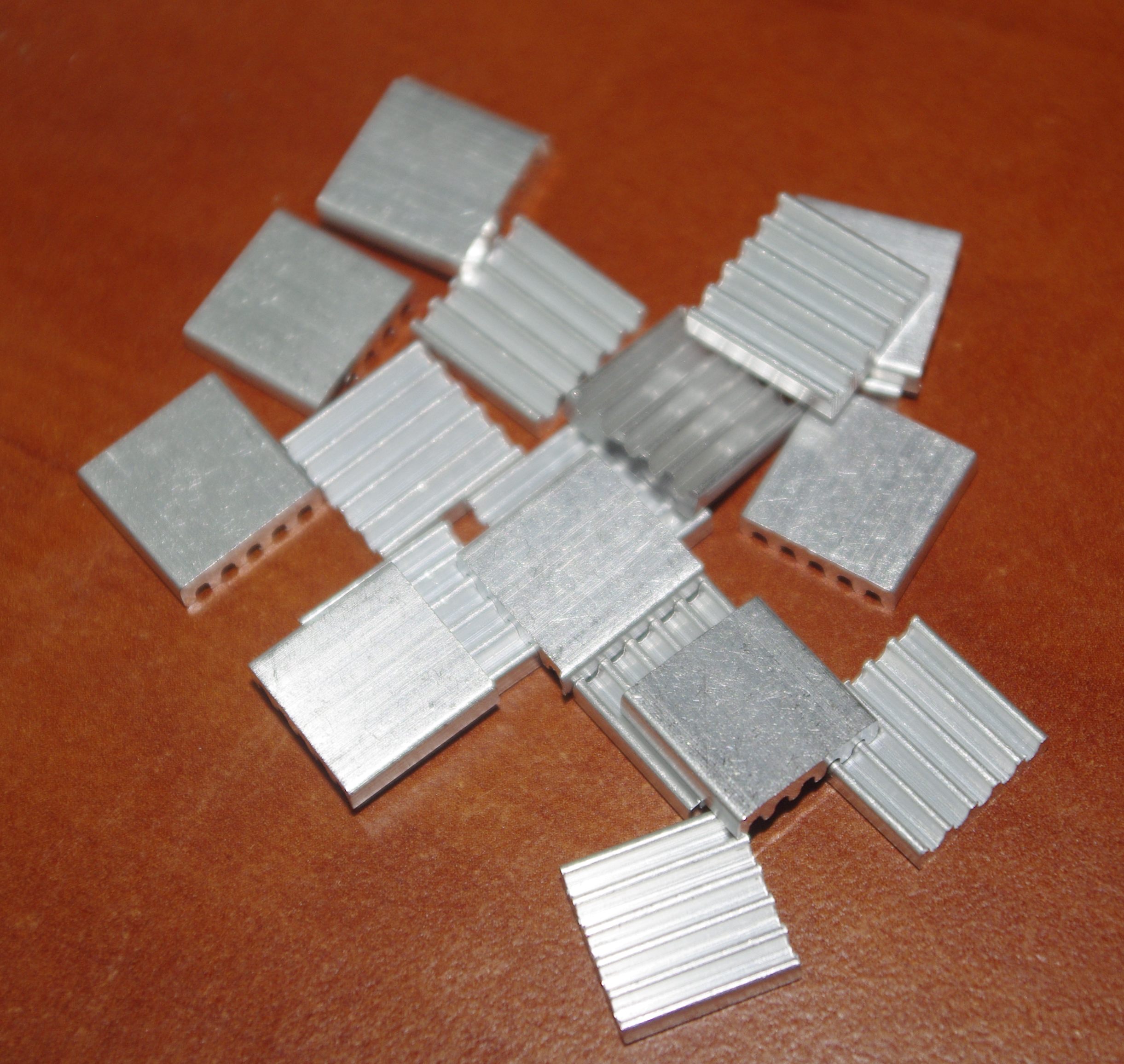
To combat the first problem, it was decided to install a radiator on the chip. For this, I ordered small aluminum radiators of sizes 12x12x3 mm (exactly under the size of the chip). A height of 3 mm was chosen because I wanted the protruding radiator not to cling to objects (in a bag, for example) and the router could stably lie on the table.
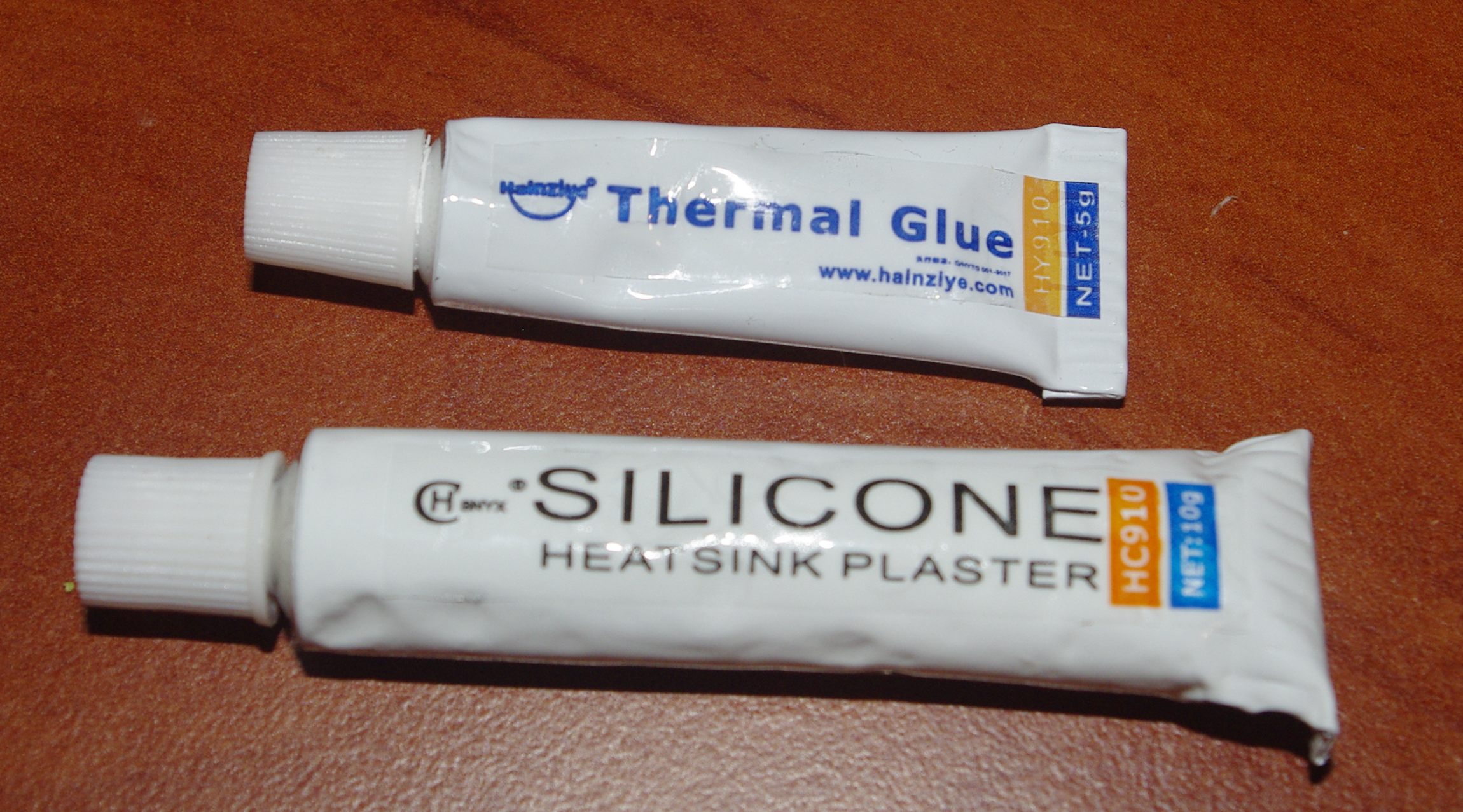
For mounting the radiator, I decided to use hot melt glue. From those available in our area - there was only “disposable” Alsil-5, which, despite its fairly good thermal conductivity, does not at all imply long-term storage. It dries in a couple of days (and if you are lucky, you can buy it already dried). Therefore, on the same aliexpress, two types of hot melt glue were ordered for high-power LED radiators - Halnziye HY910 and Hcbonyx HC-910 .
The reviews on the specialized forums are not bad, although experts still recommend using two-component epoxy hot melts for serious tasks, like Thermopox 85CT . But go find him ...
Just in case, here are the comparative characteristics of thermal conductivities used by me hot melt, found on the Internet.
Thermoglue Halnziye HY910 - thermal conductivity 0.975W / mK
Thermoglue Alsil-5 - thermal conductivity 1.4-1.6W / mK
Thermoglue hcbonyx HC-910 - thermal conductivity 1.7W / mK
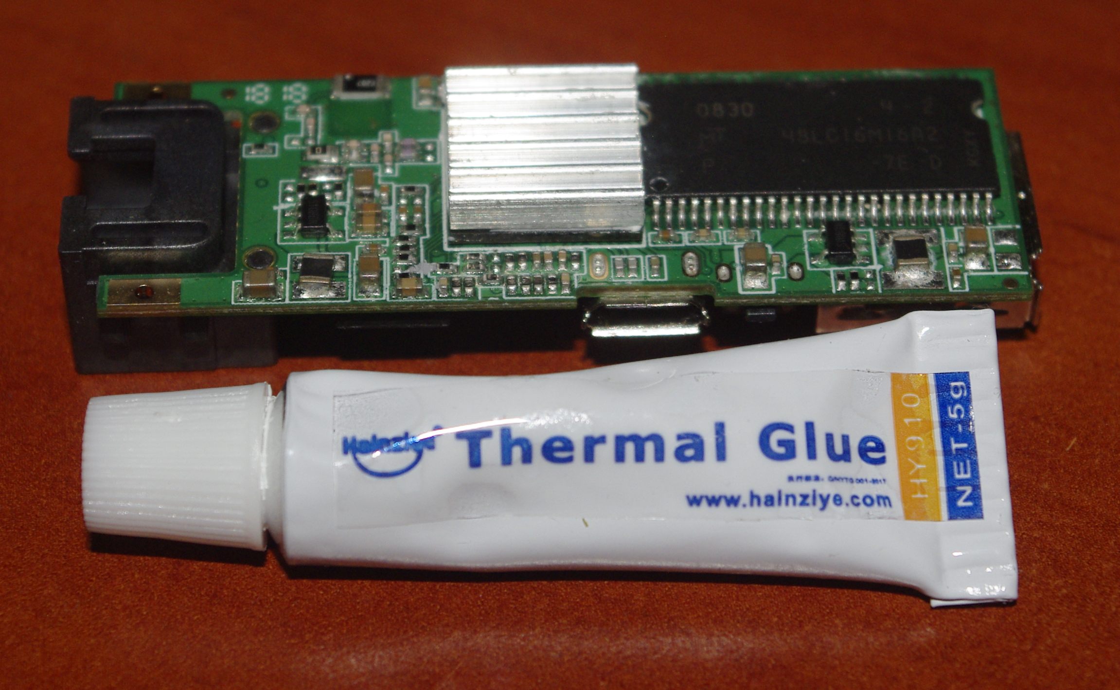
In order to install a radiator, I had to cut the case (including to improve heat transfer). To do everything as neatly as possible, I first traced the dimensions of the board onto thick paper, cut a hole for the chip, and then put the cardboard template into the case. Then everything is simple - we draw out the contours of the hole with a pencil, cut it with a stationery knife and polish it with a file.

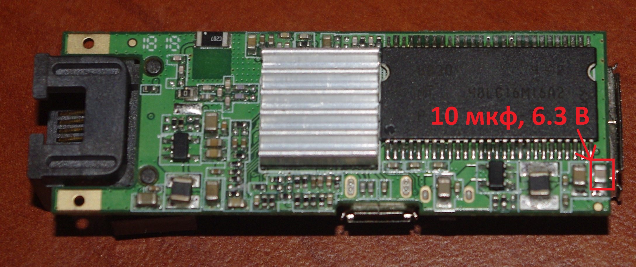
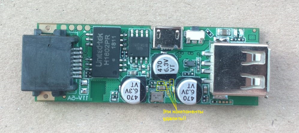
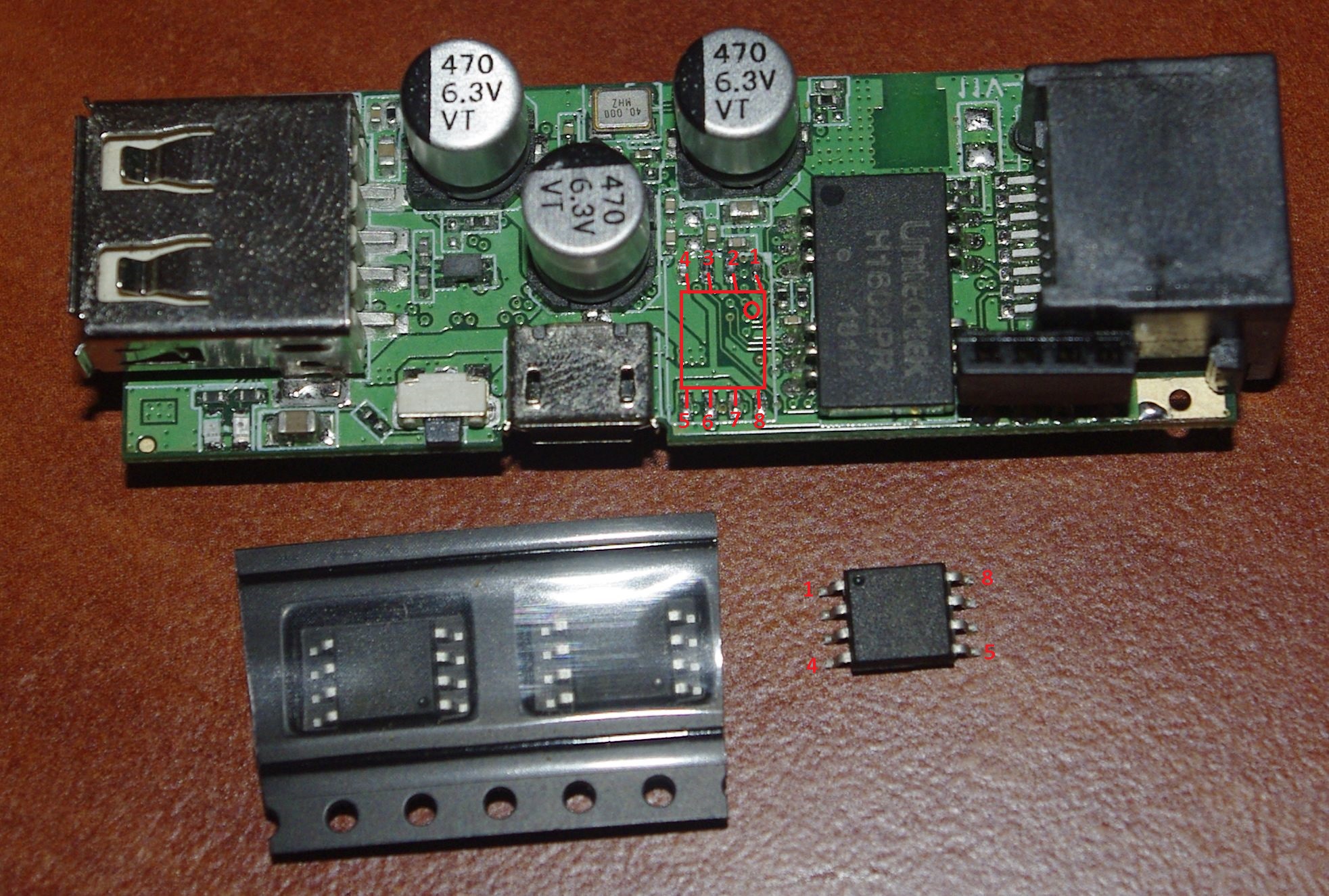
In parallel with the installation of the radiator, it is necessary to solder the missing ceramic SMD capacitor 10 μf 6.3 V to the router in a 3.3V converter circuit. (following the advice of the user return1 ). Installation location shown in the picture:
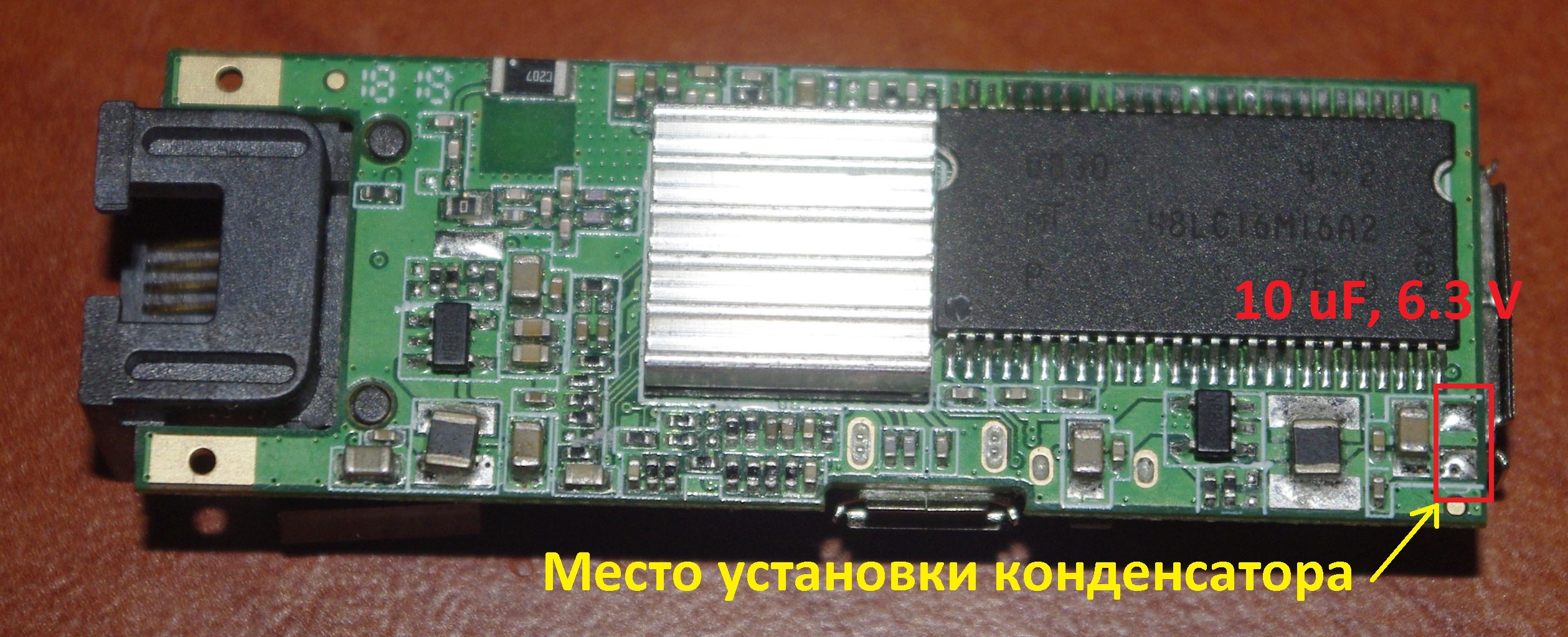
According to reviews, the current consumption of the device decreases and becomes more stable. Presumably, in the 3.3V converter, pulsations appear on the output, which disable the processor. The capacitor smoothes these pulsations.
Important! Try to install the radiator and solder the capacitor BEFORE launching and operating the router. Otherwise, it may turn out that “Borjomi drink” is too late ...
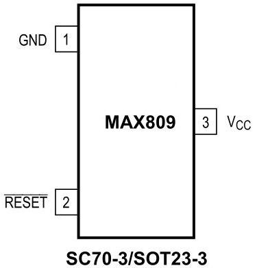
People solve the power problem by installing, instead of the regular RC-chain of the router, specialized power supply monitor circuits, for example, KR1171SP28 , DS1816 or MAX809TTR . I immediately liked the option of using Maxim power supply supervisors. The two main tasks that supervisors can solve are to keep the controller in a reset state until the supply voltage reaches a predetermined value and does not stabilize, or resetting the controller when the supply voltage drops below a critical level or when the voltage drops suddenly. Also from the advantages of this type of supervisors, it can be noted that the installation of the chip does not require additional components, and the size of this semiconductor device lies in the places of the removed elements (yes, you must first remove the unnecessary resistors and capacitors, and then also go braid on contact pads).
Search on aliexpress did not give anything, but it gave a search in the catalog of CHIP and IP where the pulse shapers (reset) of MAX809TEUR + T (with a voltage of 3.08 volts) were detected, one of which was successfully soldered to the router.

By the way, I can not fail to mention the Chinese USB soldering iron , without which I would never cranked this procedure (even with the vaunted microwave ...).
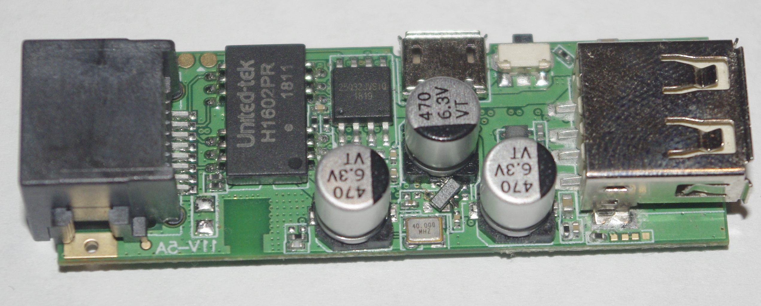
In order not to drive the wasted soldering iron, at the same time I decided to solder a contact block to the contact pads of the UART console (patch) to simplify the connection of dupont-wiring from Arduino-designers. The pins of the pads with the contact pitch of 2 mm matched perfectly (the standard widespread 2.54 mm is already wide). These are , for example. To make it easier to solder, I with the help of tweezers bent the tips of the contacts with the letter “G” and tinned the fingers on the router board.
Then it was enough to install the pad on the patch and slightly warm the joint before melting the solder. It is important not to overdo it (which is easy to do with a powerful soldering iron), otherwise the snouts can simply fall back from overheating. In this case, the picture shows a backup test-point, where you can solder.
By the way, it is possible to solder contacts using another method, but the case is simply not closed.
At this preparatory part ended and the main one began.
Part Two, “Programmer”
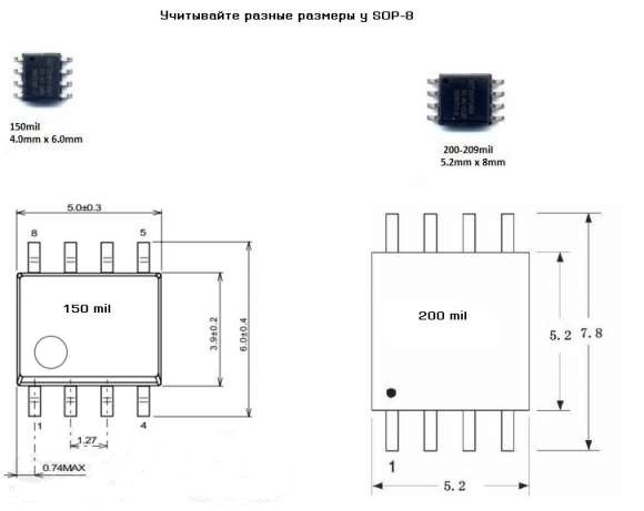
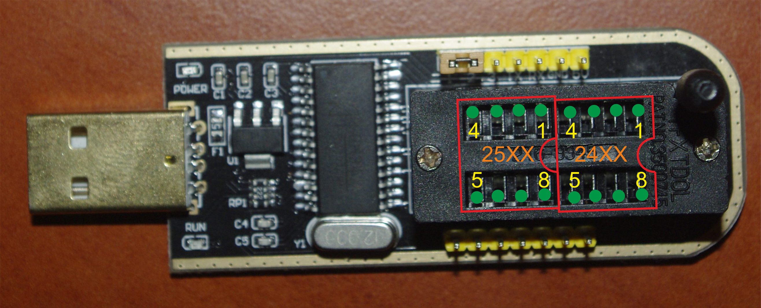
As I mentioned at the beginning of the article, there is little memory in the router, only 4 MB. Of course, I can remember someone and the fact that "640 KB should be enough for everyone." But having spent a week trying to shove all the necessary packages into the self-assembled openwrt for the D-Link DIR-320 (and there is in fact 8 MB (!)), I now know for sure that it’s not worth saving on memory. Therefore, it was decided to change flash to a more capacious and at the same time having a reasonable cost (so as not to be more expensive than the router itself). Replacement requires chips with an effective frequency (SPI Clock rate) not lower than 100 MHz and a supply voltage of 3.3 V. Of the manufacturers, Winbond or any other (En = Eon, Mx = Macronix, Pm = PMC, At = Atmel). From what openwrt.org advises are W25Q128BV , MX25L128 (35F), S25FL128P, S25FL129P, GD25Q128C, GD25Q128CSIG. The number 128 in the marking tells us that the size of the flash drive is 16 MB (128Mbit = 16Mb). The choice of a nominal of this size is due to the fact that a cheap Chinese programmer of the 24 / 25th CH341A memory chip (about it below) can work with such volume without dancing with a tambourine. For fans, I can say that 32 MB can be soldered (for example, W25Q256FV, MX25L25635F, N25Q256A, MX25L25645GM2I-10G and even 64 MB (MX25L51245G, MT25QL512AB). But I would like to note that for 64 MB of modules, the memory tags are far from humane. I note that the talk about memory chips is ONLY in the SOP8 package as the most convenient for soldering. Of course, you can take chips in WSON8 packages with contact pads instead of legs, but the soldering is too laborious and the result may not meet the expectations.
You can flash the memory chip in several different ways, depending on what is available:
a) There is a diode / capacitor and a parallel port (the simplest programmer) - see the firmware manual on the Czech website or in Russian .

b) There is any Arduino (Pro, Micro, Nano, etc.) - we prepare one of them for our SPI flash programmer according to the following recipe .
c) If there is a Raspberry Pi - look here
d) There is a “popular” USBASP programmer (about which they once wrote on Habré) - we prepare it according to the recipe number 2 .
e) There is only a desire and some money - we buy Chinese CH341A programmer for 24/25 SPI flash on aliexpress and calmly start working.
The flash drive itself is connected to the programmer (s) as follows:
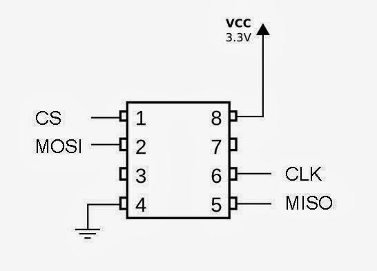
A USB flash drive can be soldered and connected to the blocks / adapters of the programmer, or you can solder the already mentioned dupont wires from the Arduino to it, and you can connect the wires to the programmer. The "workers" of the flash are MISO , MOSI , CLK , CS , VCC and GND contacts. If programming is carried out without removing the chip from the board, it is best to unsolder during operation and slightly raise the VCC contact above the board plane. After completion of work - press the foot to the board and solder.
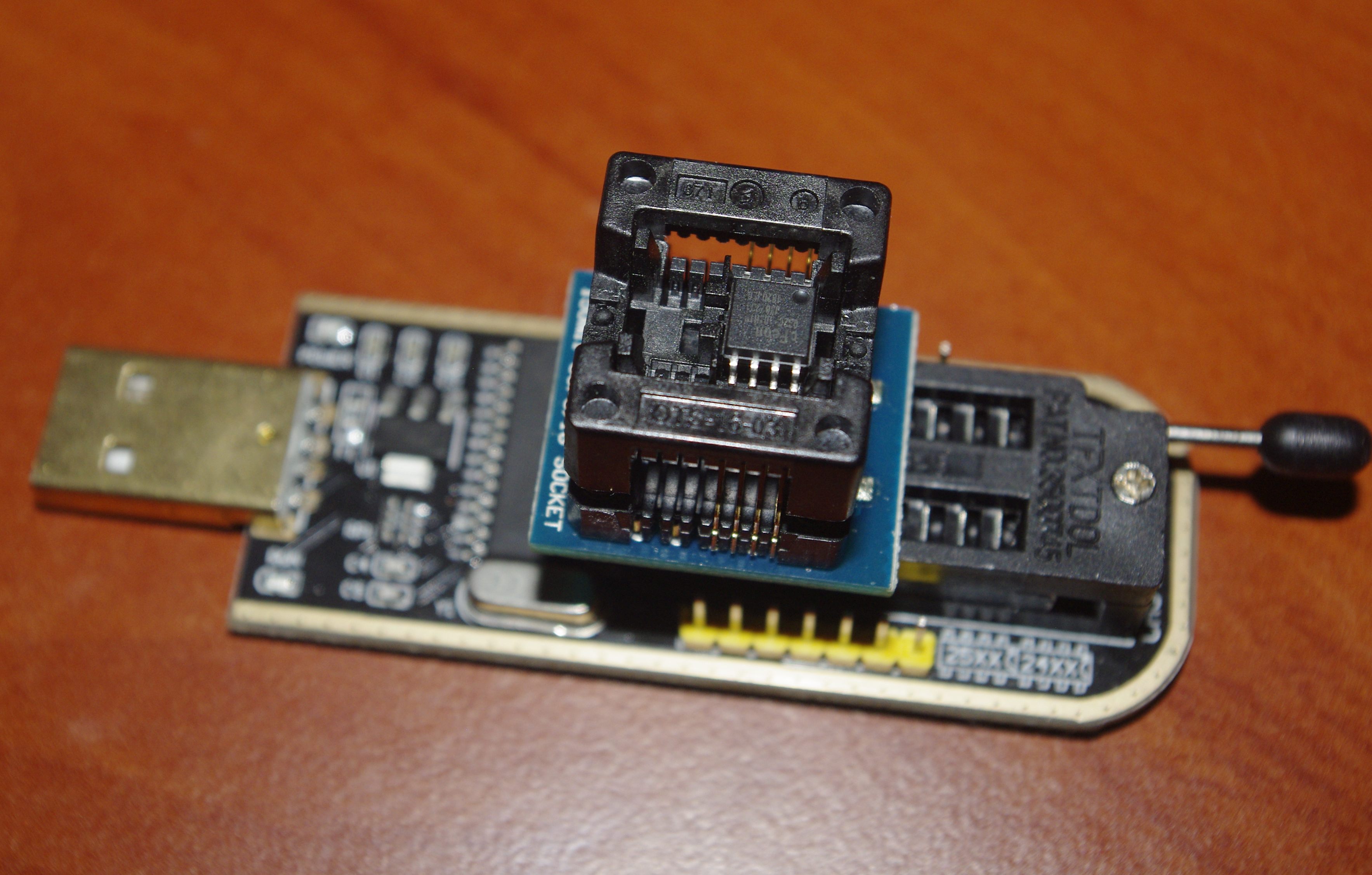
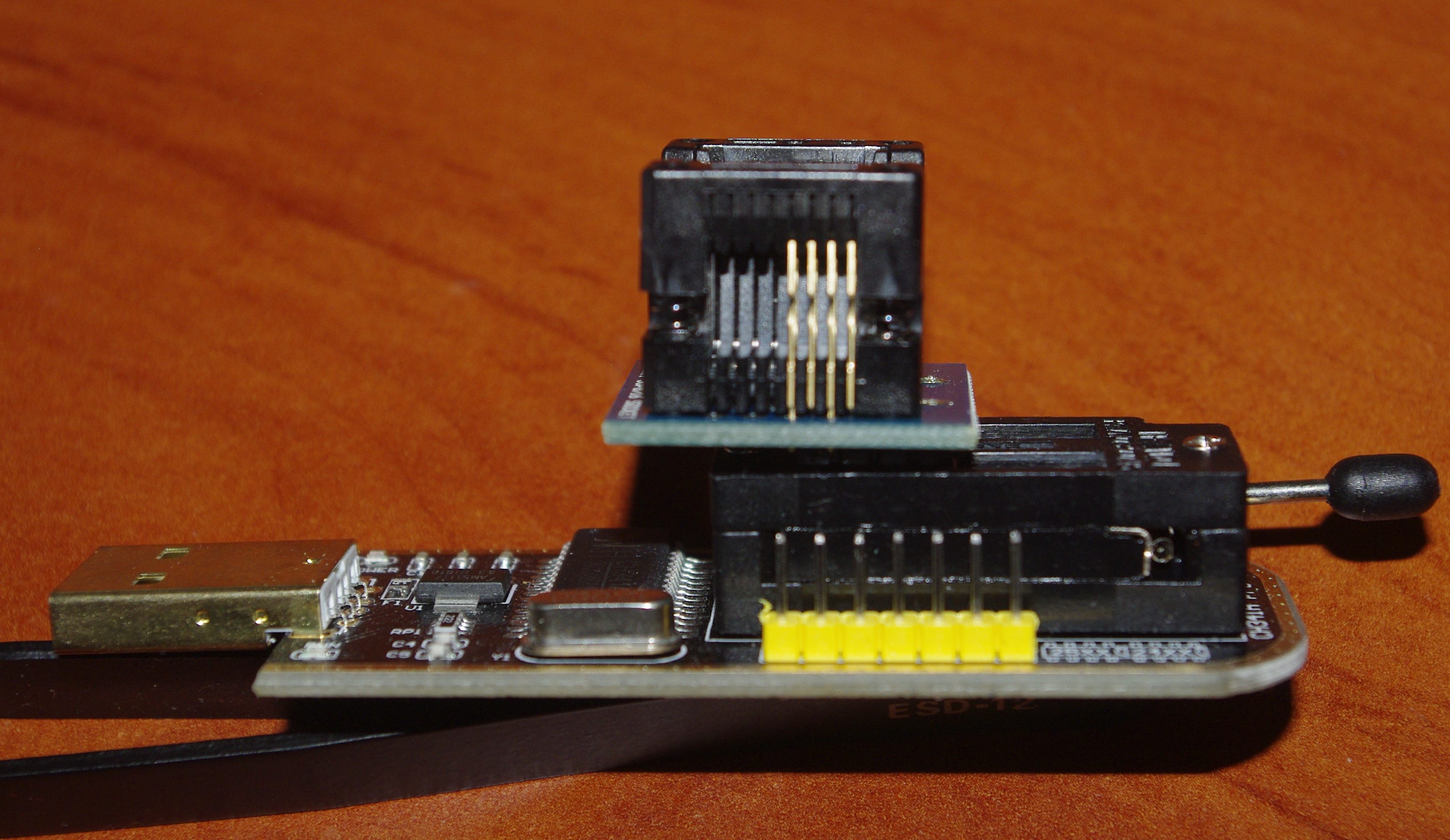
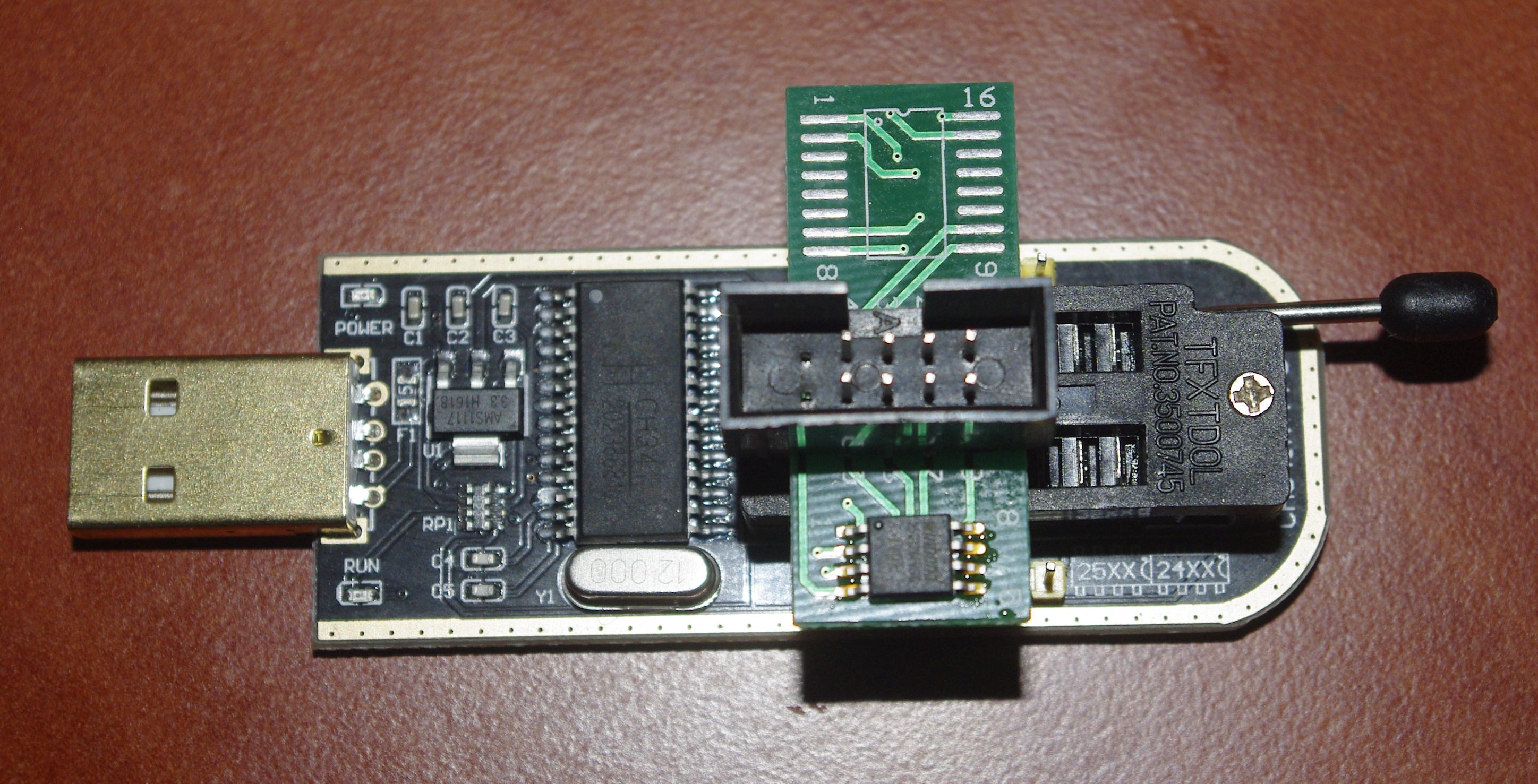
Since I didn’t have the desire to look for the LPT port, I decided to act on the last option e) and purchase an additional piece of iron in my park. This piece is called CH341A and is, oddly enough, a programmer based on the chip CH341, the author's development of the "widely known" Chinese mega-corporation Jiangsu QinHeng Ltd. :)
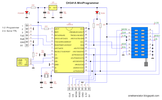
When ordering only the programmer, I strongly recommend additionally buying an adapter from SOP8 / SOIC8 cases to DIP cases and a clip-clip for working with chips.
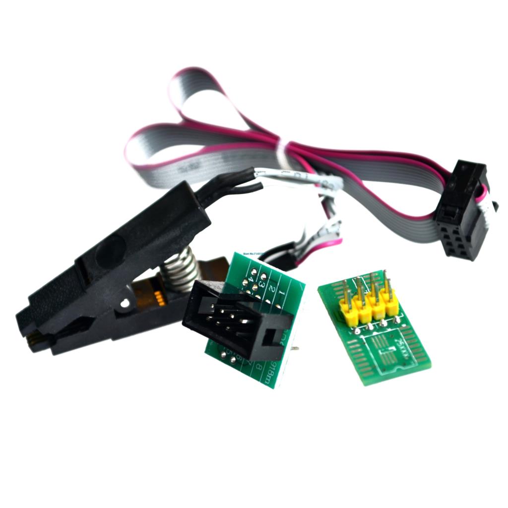
You can not chase the meager savings, and buy immediately a ready-made set consisting of the programmer and all the necessary adapters, then you will get in addition to the above two adapters and an adapter for programming 1.8 V chips.

From my own experience I will say that the clip-clothespin works once a time and most likely the chip will have to be soldered and put into the SOP8-DIP adapter or even soldered to the pads on the programmer itself.
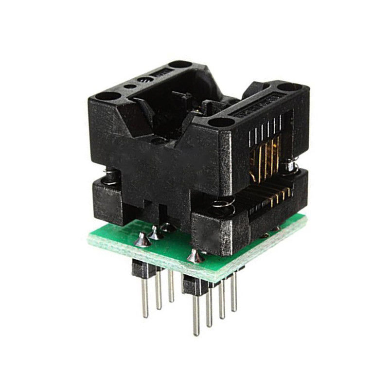
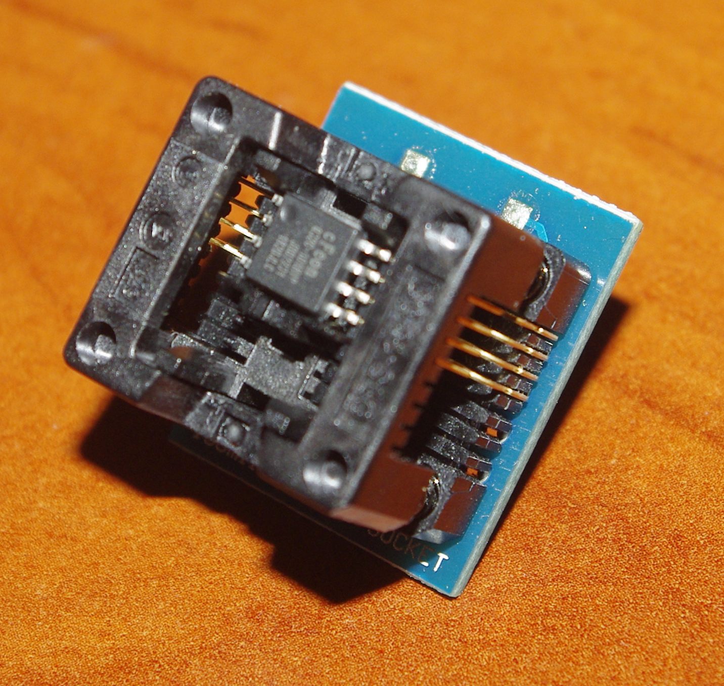
Addition : my adapter has finally come, or how correctly it is called the SIF8-DIP8 150 mil ZIF adapter . This adapter is suitable for microcircuits with a housing width of 150mil, lead pitch 1.27mm. In addition to 150 mil, there may be 200 mil, so it’s important to pay attention to this when ordering at auctions (I have chips and so, so there are two adapters).
The thing is incredibly convenient, the chip is clamped easily, at ease and very clearly (the system resembles pliers). To do this, simply press the spring upper part of the case, put the chip on the exposed sites and release this part of the case back. The spring-loaded top contacts come out when released and the chip is automatically clamped (photo for clarity, because the 200 mil chip is in the 150 mil adapter, so do not kick it, it stuck what was at hand). Then install in the programmer, looking where we have leg 1 (circle on the chip). It turns out like this:
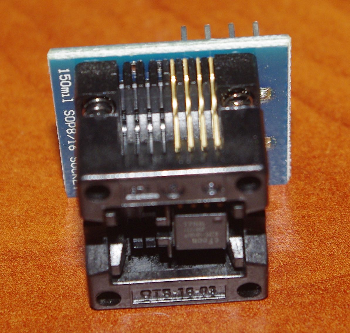

I filmed a native memory chip using a hot air soldering station, and for those who do not have such equipment, I recommend strongly using the Rosa alloy method . After work, be sure to remove the remains of the Rosa alloy with braid from the board and the microcircuits, away from sin.
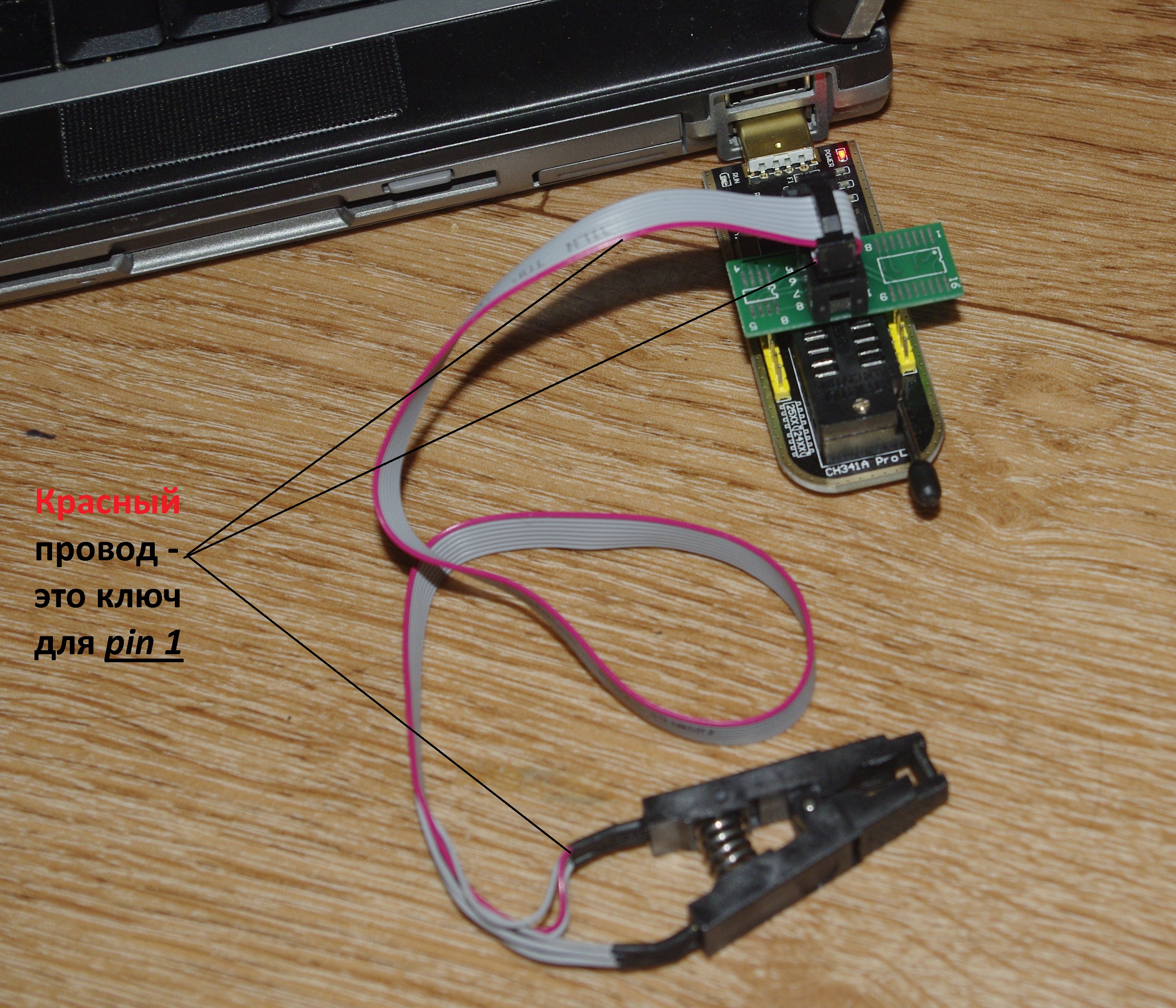
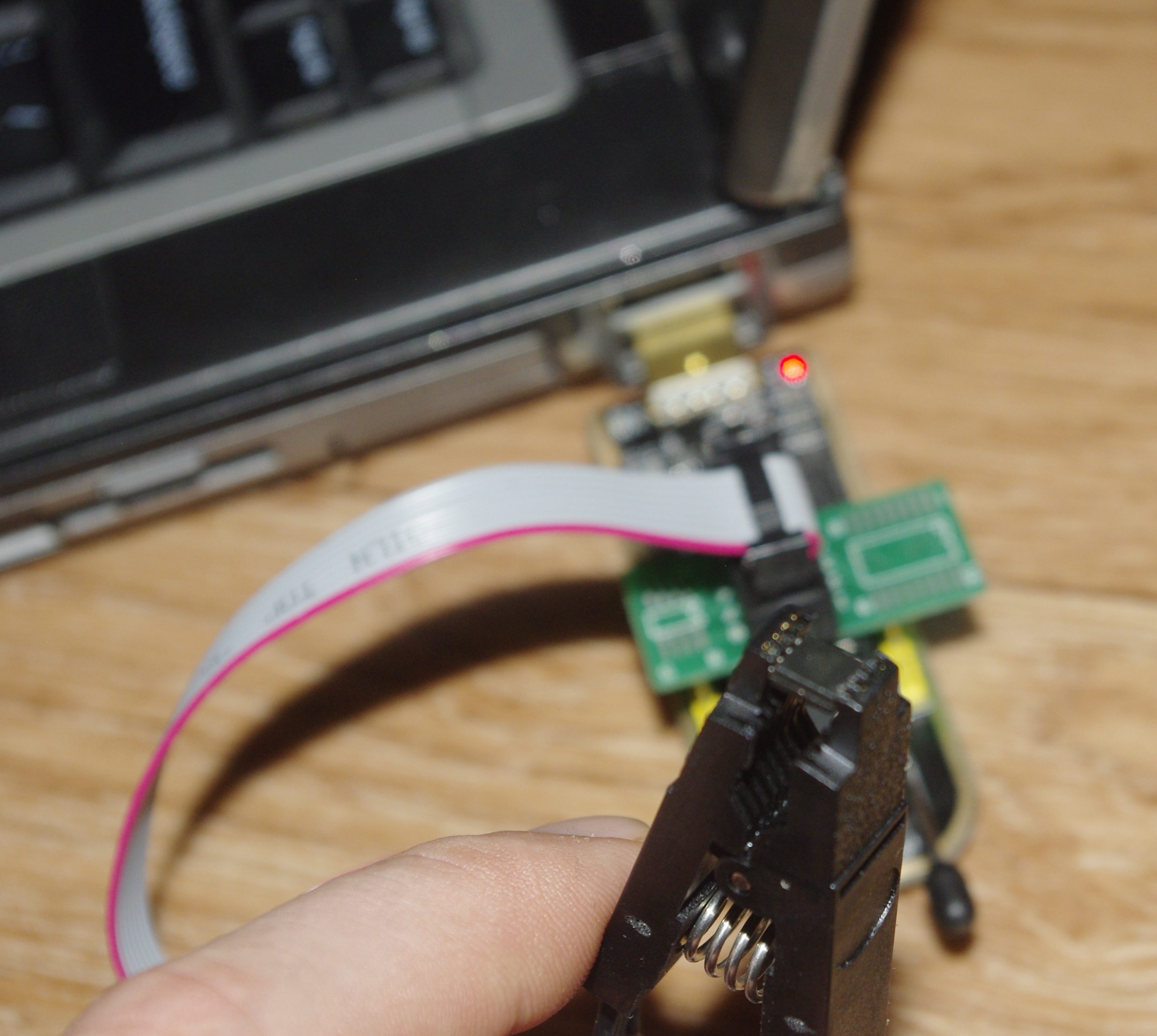
The removed microcircuit is connected to the programmer (for someone how and what happens). I was too lazy to solder, I honestly tried to clamp with a clip, as a result, my legs strongly slanted down with a spring of clips. But the benefit of soldering back, I did not intend to 4 MB flash, and good contact was to ensure trouble-free reading. So it happened. Nota bene for those who solder the microcircuit - carefully look at the digits on the adapter boards and solder them in accordance with them. In the case of a clip, the red wire on the cable is keyed and falls on foot number 1.
Having dealt with the iron, you have to deal with the software. As I already wrote, on Habré this programmer periodically pops up in articles . From where it is clear that it works without problems with all modern operating systems (for example, in Windows 10 drivers are pulled from the network automatically, and in Linux they have been in the kernel for several years). But, but you never know what will happen, here you can find the driver (for the Serial / Parallel mode) with separate files just in case. For programming in Windows, Chinese software by SkyGz is often used. For Linux, there are open projects ch341prog (SPI) and ch341eepromtool (I2C), you can use the "people's" flashrom . Since I use Windows, and the majority of users are not very positive about the "Chinese program" (especially about the new 1.28 ... 1.30 versions), in order not to tempt fate, the chip was read using the simple, reliable Russian programmer AsProgrammer version 1.4.0 . By the way, if something suddenly did not like something / is not clear, or for example, you need to add a new chip, you can easily write in the topic "technical support" and get a quick feedback.
I will allow myself a small digression and explain my unwillingness to install a 32 MB flash drive (the price difference from 16 MB is not critical). The fact is that neither in the Chinese programs (version 1.29 or 1.30), nor in the mentioned AsProgrammer support of the microcircuits ala W25Q256FV, MX25L25635F, N25Q256A, MX25L25645GM2I-10G is stated. Perhaps the reason for this is that for an SPI flash, the maximum amount is 128 Mbps (the maximum that can be addressed by the 3-byte addressing mode adopted by JEDEC). And here the options are not so much. For example, you can use the modified flashrom to write the first half of a w25q256 chip (16 MB in size), as familiar to this program, a 16 MB w25q128 chip and stick a correct bootloader (Breed, for example) and factory partitions with “service” information (mac -address of the router, wi-fi calibration, etc.). And already booted in bootloader mode (in case of successful recognition of the entire volume of the chip), it would be possible to flash the precompiled firmware from it. You can even buy flash drives for the future and wait until support for such volumes appears in the broken versions of Chinese software to the ch341a or when the flashrom is finished. Summing up, it is better to take 16 MB :) for “tired of reaching for the stars, pick up what is lying under your feet.”
Working with AsProgrammer is extremely simple, first select your chip in the "Chip" menu, and then click on the "Read" button. A couple of minutes and a dump in our pocket :)

The factory full flash consists of a bootloader, a pair of sections for storing various settings and the firmware itself.
0x00000000-0x00030000: "Bootloader"
0x00030000-0x00040000: "Config"
0x00040000-0x00050000: "Factory"
0x00050000-0x0011282a: "Kernel"
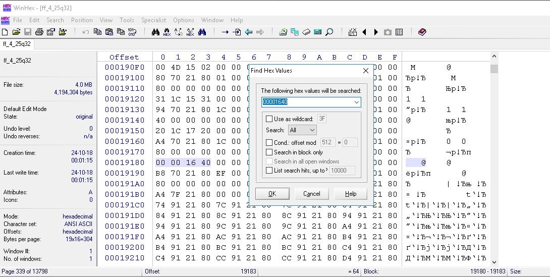
The saved dump file needs to be opened in any HEX editor (I'm used to using WinHex ) and at 105720 (the address in decimal system in hex will be 00019CF8) change 40 00 to 00 01 for a 16 MB flash (well, or 80 00 if Suddenly you decide to save a dozen cents and buy an 8 MB IC chip). We save the modified firmware for future use. By the way, the address 105720 is not the point of some kind of binding and other numbers may well be there, especially if you have already tried to unlock the bootloader for openwrt firmware, etc. Therefore, if all of a sudden, nothing happens, and the cherished “40 00» 105720 , HEX- « 00 00 16 40 ». /.
? , UART TFTP, .
0 ( ). . , , :)
, openwrt-
— openwrt. , ( « ») sysupgrade-, - . , openwrt . (, Tp-Link TL-WR741ND , Tp-Link TL-MR3020 , D-Link DIR320A1 , ...), ( ).
*nix , VirtualBox Ubuntu x64 ( -).
sudo apt-get update
. Ubuntu 16.04 LTS :
sudo apt-get install build-essential subversion mercurial libncurses5-dev zlib1g-dev gawk gcc-multilib flex git-core gettext libssl-dev unzip
git clone . — openwrt.
18.06.1
git clone git: //github.com/openwrt/openwrt.git -b v18.06.1
18.06.0
git clone git: //github.com/openwrt/openwrt.git -b v18.06.0
17.01.5
git clone git: //github.com/openwrt/openwrt.git -b v17.01.5
17.01.4
git clone git: //github.com/openwrt/openwrt.git -b v17.01.4
17.01.3
git clone git: //github.com/openwrt/openwrt.git -b v17.01.3
17.01.2
git clone git: //github.com/openwrt/openwrt.git -b v17.01.2
17.01.1
git clone git: //github.com/openwrt/openwrt.git -b v17.01.1
17.01
git clone git: //github.com/openwrt/openwrt.git -b v17.01.0
15.05.1
git clone git: //github.com/openwrt/archive.git -b v15.05.1
15.05
git clone git: //github.com/openwrt/archive.git -b v15.05
14.07
git clone git: //github.com/openwrt/archive.git -b v14.07
12.09
git clone git: //github.com/openwrt/archive.git -b v12.09
openwrt. cd ,
./scripts/feeds update -a && ./scripts/feeds install –a
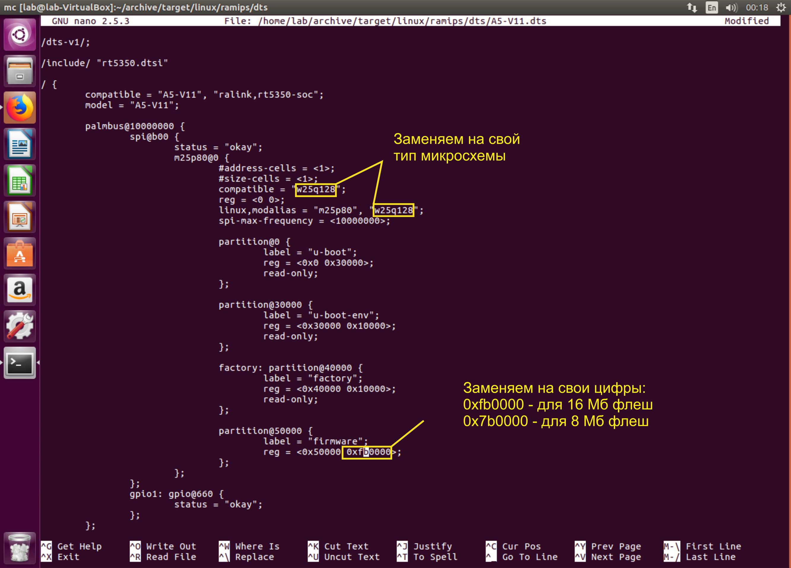
" " , , , 4 . . openwrt target/linux/ramips/dts/A5-V11.dts ( nano, F4 mc).
,
make defconfig
, make menuconfig . — :
Target System: Ralink RT288x/RT3xxx
Subtarget: RT3x5x/RT5350 based boards
Target Profile: A5-V11
and then - by analogy with the openwrt build for other routers (I gave the links above), modify the set of packages in the way we want and save the configuration (to the .config file). By the way, if you plan to change configurations frequently, you can make a backup copy each time with the command scripts / diffconfig.sh> mydiffconfig , so each time we save our configuration changes to the file mydiffconfig. After compiling the desired configuration (and selecting all the necessary packages), run the build with the make command.
Due to the independent compilation of the kernel, you may encounter the fact that many packages from the official repositories for installation will not work. This should be taken into account and more often set the flag “M” opposite the desired package. Then these packages can be found in the openwrt / bin / ramips / packages folder and uploaded to some HTTP server to create your own personal repository with blackjack and ... for OpenWRT :).
By the way, I remembered that it is very convenient to run the make command in the following form:
make V = 99 2> & 1 | tee build.log | grep -i error
In this case, the compiler saves a full detailed copy of the debugging information about the build to the build.log file in the openwrt directory and displays only errors. Then this log is conveniently attached to the forums to find the cause of the error or ask a question. In addition, it remarkably allows you to identify packages on which the compiler stops working. You can find the text mentioned in the log by searching the directory with the command
grep –Hr “TEXT” <path to the search directory> | cut –d: -f1 | sort -u
But I sincerely hope that the compilation will be successful and I will not have to look for errors. After the process is complete, you can find the firmware files in the bin folder of the openwrt directory, something like openwrt-ramips-rt305x-a5-v11-squashfs-sysupgrade.bin . We take this file and proceed to the final stage.
Part Four, console
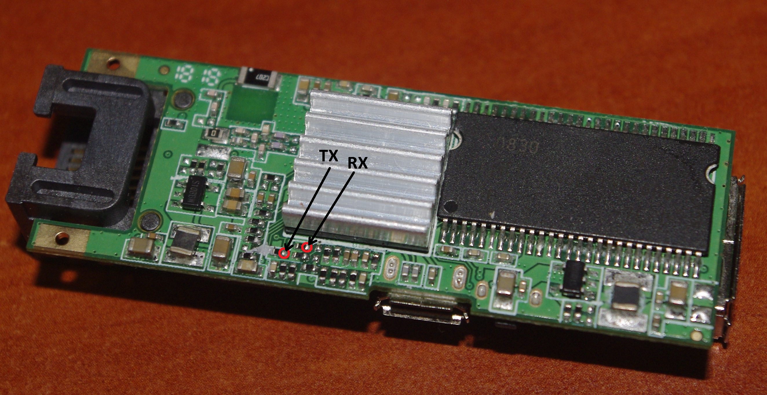
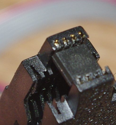
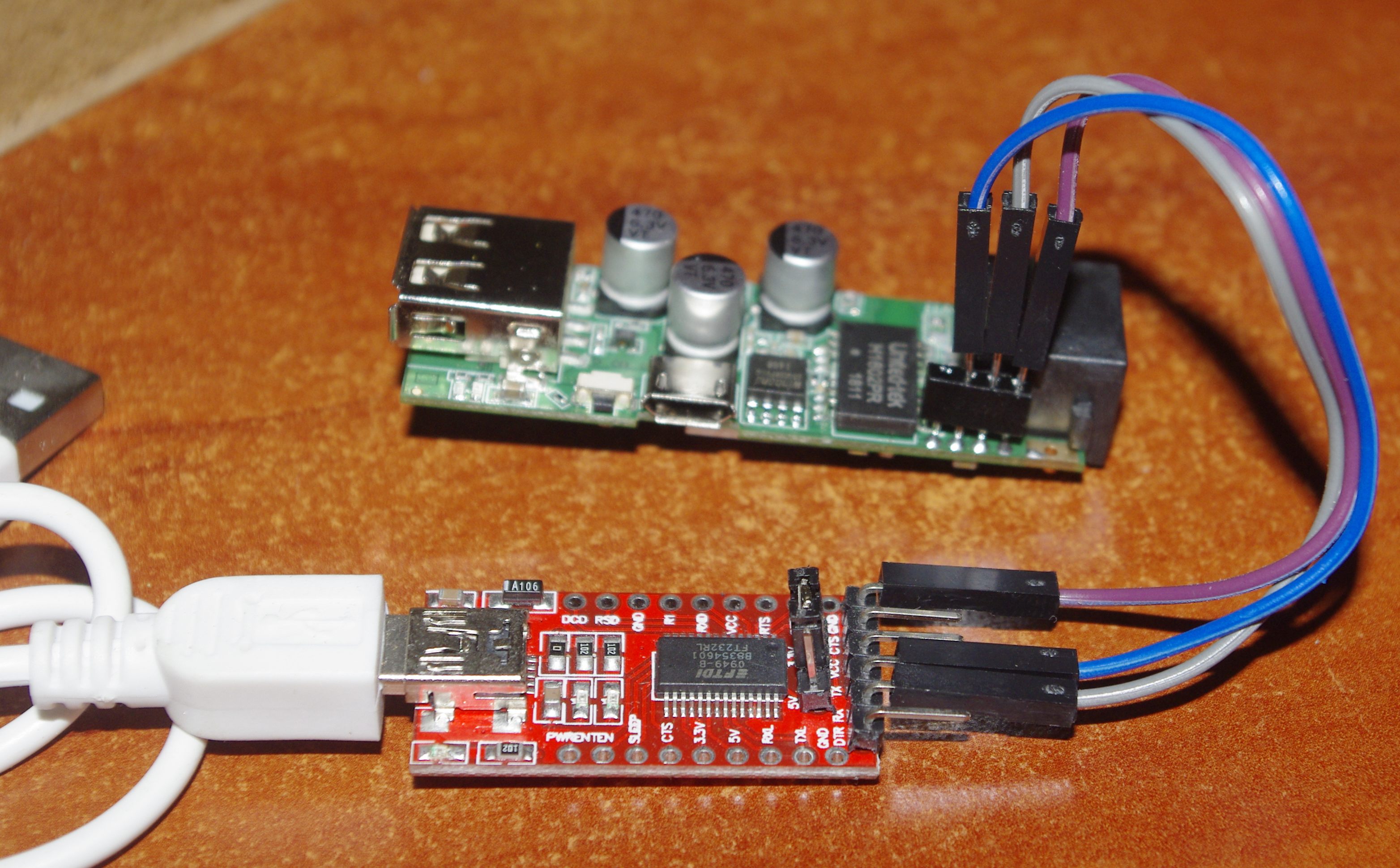
After the firmware is assembled in the depths of the virtual machine, all that remains is to throw it into the router. I like the version with UART (not for nothing did I solder the pad to the contact heels). To connect, you need either a USB to TTL UART adapter, or at least a data cable from the old Siemens. I, fortunately, had such an adapter on an FT232 microcircuit (the CP2102 and the omnipresent CH340 are also suitable). Pinout pads shown in the photo.
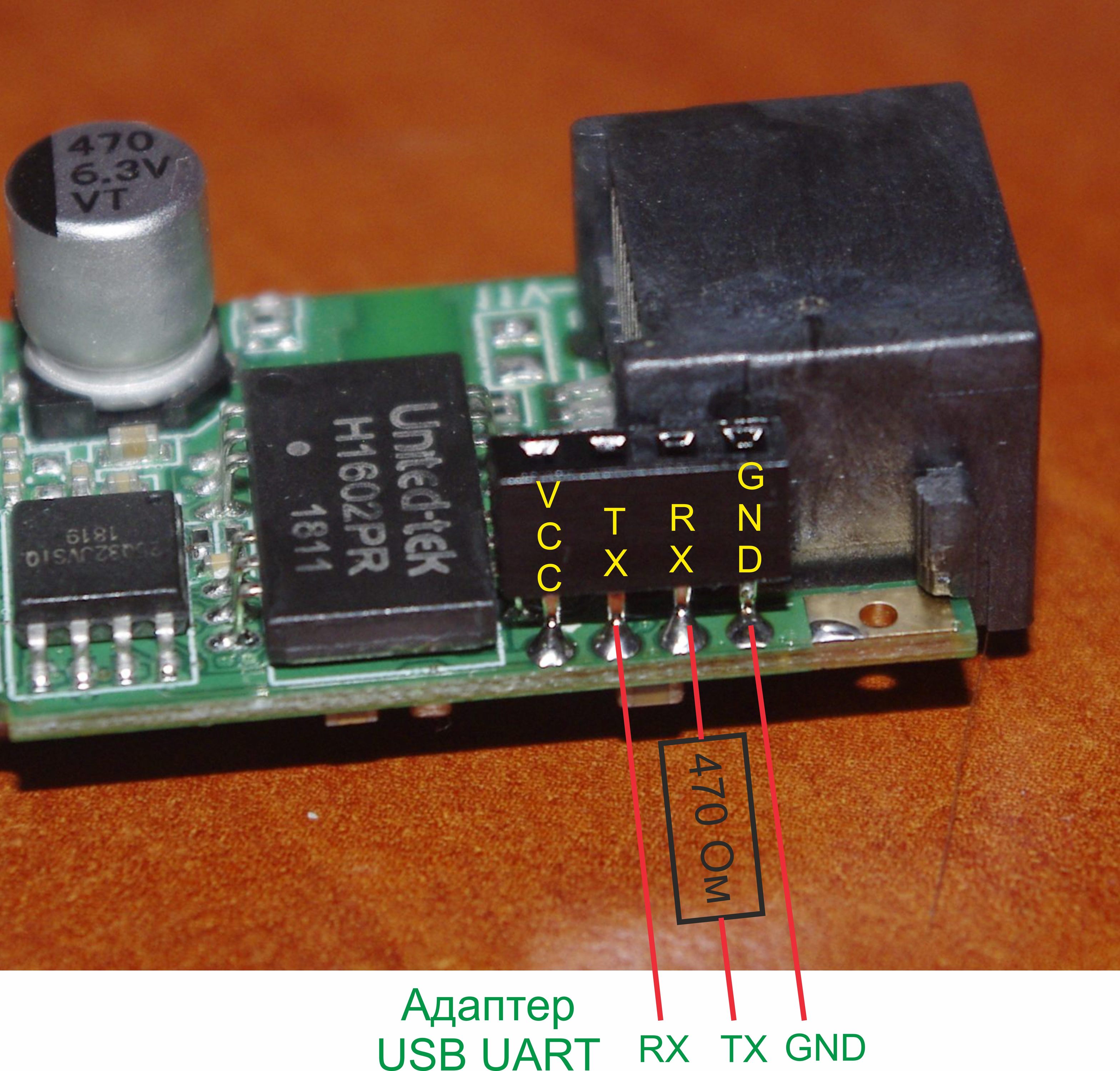
Connect the contacts to the adapter as follows:
GND router → GND adapter
RX router → 470 Ohm-1 kΩ resistor → TX adapter
TX router → RX adapter
Let me explain why you need a resistor. When I turned on the router connected to the adapter, it hung up and started to get warm.
In this case, the terminal managed to fall out something like
ϟr▒▒▒▒▒▒▒▒▒▒▒▒▒▒▒▒1▒▒▒▒▒▒▒▒▒▒▒▒▒▒▒▒▒A▒▒ (0▒▒▒▒▒
? ▒▒▒ {▒F▒▒▒▒▒ ^ ▒▒B▒▒▒KӉSP @ ▒ (Y <0▒0▒ $ ▒ @ ▒▒▒ ▒▒▒ 怘 ▒▒ff▒▒▒▒▒`▒▒ ▒▒▒▒▒▒▒▒▒x▒▒x▒▒▒▒▒x ~ `▒▒ 怘 ▒▒▒▒▒x▒▒f▒▒▒▒▒f▒▒`ff▒▒▒▒▒▒▒ ▒▒fx▒▒▒f ~ f▒f▒▒`fxf▒▒▒▒`fx▒▒ ~ ▒x▒f▒▒f ~ f▒`▒f▒fx▒ ~ ▒f▒xf▒ ~ fx ▒▒x▒▒▒xx▒▒▒▒xx▒▒▒▒x▒▒▒xf▒▒`x▒▒▒▒▒▒fxf▒x▒▒`▒▒▒f▒▒f▒▒f▒fxx▒ x▒ 枘 ▒x▒f▒▒
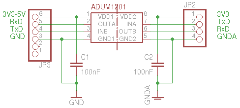
The resistor (you can connect any, in the range from 470 ohms to 1 kOhm) fixed everything. And here , for example, the author generally advises using the AduM1201 digital signal isolator to connect to the UART for decoupling. But I had enough resistor, which is what you want.
Receive the signal from the router using the terminal program on the PC. I somehow didn’t work with the national favorite Putty, and I use the excellent Terminal program. Select the desired virtual COM port (on which our USB-UART sits), set the parameters:
Speed: 57600
Data Bits: 8
Parity: None
Stop Bits: 1
And click Connect. Now, when power is applied to the router, we will see the bootloader logs in the console:
U-Boot 1.1.3 (Apr 11 2013 - 00:10:51)
Board: Ralink APSoC DRAM: 32 MB
relocate_code Pointer at: 81fb4000
spi_wait_nsec: 42
spi device id: ef 40 18 0 0 (40180000)
Warning: un-recognized chip ID, please update bootloader!
raspi_read: from: 30000 len: 1000
*** Warning - bad CRC, using default environment
============================================
Ralink UBoot Version: 3.6.0.0
ASIC 5350_MP (Port5 <-> None)
DRAM_CONF_FROM: Boot-Strapping
DRAM_TYPE: SDRAM
DRAM_SIZE: 256 Mbits
DRAM_WIDTH: 16 bits
DRAM_TOTAL_WIDTH: 16 bits
TOTAL_MEMORY_SIZE: 32 MBytes
Flash component: SPI Flash
Date: Apr 11 2013 Time: 00: 10: 51
============================================
icache: sets: 256, ways: 4, linesz: 32, total: 32768
dcache: sets: 128, ways: 4, linesz: 32, total: 16384
The CPU freq = 360 MHZ
estimate memory size = 32 Mbytes
Please choose the operation:
1: Load system code to SDRAM via TFTP.
2: Load system code then write to Flash via TFTP.
3: Boot system code via Flash (default).
4: Entr boot command line interface.
7: Load Boot Loader code then write to Flash via Serial.
9: Load Boot Loader code then write to Flash via TFTP.
4 3 2 1
You choosed 3
0
3: System Boot system code via Flash.
Booting image at bc050000 ...
raspi_read: from: 50000 len: 40
. Image Name: MIPS OpenWrt Linux-3.7.5
Created: 2013-04-11 14:41:22 UTC
Image Type: MIPS Linux Kernel Image (lzma compressed)
Data Size: 915849 Bytes = 894.4 kB
Load Address: 80000000
Entry Point: 80000000
raspi_read: from: 50040 len: df989
... Verifying Checksum ... OK
Uncompressing Kernel Image ... OK
No initrd
Transferring control to Linux (at address 80000000) ...
Giving linux memsize in MB, 32
Starting kernel ...
[0.000000] Linux version 3.7.5 (lich @ lich-pc) (gcc version 4.6.4 20121210 (prerelease) (Linaro GCC 4.6-2012.12)) # 2 Thu Apr 11 22:41:02 CST 2013
[0.000000] bootconsole [early0] enabled
[0.000000] CPU revision is: 0001964c (MIPS 24KEc)
[0.000000] Ralink RT5350 id: 1 rev: 3 running at 360.00 MHz
[0.000000] Determined physical RAM map:
[0.000000] memory: 02000000 @ 00000000 (usable)
[0.000000] User-defined physical RAM map:
[0.000000] memory: 02000000 @ 00000000 (usable)
[0.000000] Initrd not found or empty - disabling initrd
[0.000000] Zone ranges:
[0.000000] Normal [mem 0x00000000-0x01ffffff]
[0.000000] Movable zone start for each node
[0.000000] Early memory node ranges
[0.000000] node 0: [mem 0x00000000-0x01ffffff]
[0.000000] Primary instruction cache 32kB, VIPT, 4-way, linesize 32 bytes.
[0.000000] Primary data cache 16kB, 4-way, VIPT, no aliases, linesize 32 bytes
[0.000000] Built 1 zonelists in Zone order, mobility grouping on. Total pages: 8128
[0.000000] Kernel command line: board = MPR-A1 console = ttyS1,57600 mtdparts = spi0.0: 192k (u-boot) ro, 64k (u-boot-env) ro, 64k (factory) ro, 896k (kernel ), 2880k (rootfs), 3776k @ 0x50000 (firmware) rootfstype = squashfs, jffs2 mem = 32M
[0.000000] PID hash table entries: 128 (order: -3, 512 bytes)
[0.000000] Dentry cache hash table entries: 4096 (order: 2, 16384 bytes)
[0.000000] Inode-cache hash table entries: 2048 (order: 1, 8192 bytes)
[0.000000] __ex_table already sorted skipping sort
[0.000000] Writing ErrCtl register = 00023ff6
[0.000000] Readback ErrCtl register = 00023ff6
[0.000000] Memory: 29632k / 32768k available (1969k kernel code, 3136k reserved, 473k data, 180k init, 0k highmem)
[0.000000] SLUB: Genslabs = 9, HWalign = 32, Order = 0-3, MinObjects = 0, CPUs = 1, Nodes = 1
[0.000000] NR_IRQS: 48
[0.000000] console [ttyS1] enabled, bootconsole disabled
[0.000000] console [ttyS1] enabled, bootconsole disabled
[0.010000] Calibrating delay loop ... 239.61 BogoMIPS (lpj = 1198080)
[0.080000] pid_max: default: 32768 minimum: 301
[0.080000] Mount-cache hash table entries: 512
[0.090000] NET: Registered protocol family 16
[0.100000] MIPS: machine is HAME MPR-A1
[0.130000] bio: create slab <bio-0> at 0
[0.140000] Switching to clocksource MIPS
[0.150000] NET: Registered protocol family 2
[0.160000] TCP established hash table entries: 1024 (order: 1, 8192 bytes)
[0.180000] TCP bind hash table entries: 1024 (order: 0, 4096 bytes)
[0.190000] TCP: Hash tables configured (established 1024 bind 1024)
[0.200000] TCP: reno registered
[0.210000] UDP hash table entries: 256 (order: 0, 4096 bytes)
[0.220000] UDP-Lite hash table entries: 256 (order: 0, 4096 bytes)
[0.230000] NET: Registered protocol family 1
[0.280000] squashfs: version 4.0 (2009/01/31) Phillip Lougher
[0.290000] jffs2: version 2.2 (NAND) (SUMMARY) (LZMA) (RTIME) (CMODE_PRIORITY) © 2001-2006 Red Hat, Inc.
[0.320000] msgmni has been set to 57
[0.320000] io scheduler noop registered
[0.330000] io scheduler deadline registered (default)
[0.340000] Serial: 8250/16550 driver, 2 ports, IRQ sharing disabled
[0.360000] serial8250: ttyS0 at MMIO 0x10000500 (irq = 13) is a 16550A
[0.370000] serial8250: ttyS1 at MMIO 0x10000c00 (irq = 20) is a 16550A
[0.390000] ramips-spi ramips-spi.0: master is unqueued, this is deprecated
[0.410000] m25p80 spi0.0: found w25q128, expected pm25lq032
[0.420000] m25p80 spi0.0: w25q128 (16384 Kbytes)
[0.430000] 6 cmdlinepart partitions found on MTD device spi0.0
[0.440000] Creating 6 MTD partitions on "spi0.0":
[0.450000] 0x000000000000-0x000000030000: "u-boot"
[0.460000] 0x000000030000-0x000000040000: "u-boot-env"
[0.480000] 0x000000040000-0x000000050000: "factory"
[0.490000] 0x000000050000-0x000000130000: "kernel"
[0.500000] 0x000000130000-0x000000400000: "rootfs"
[0.520000] mtd: partition "rootfs" set to be root filesystem
[0.530000] mtd: partition "rootfs_data" created automatically, ofs = 380000, len = 80000
[0.550000] 0x000000380000-0x000000400000: "rootfs_data"
[0.560000] 0x000000050000-0x000000400000: "firmware"
[0.580000] ramips-wdt ramips-wdt: timeout value must be 0 <timeout <= 35, using 35
[0.600000] TCP: cubic registered
[0.610000] NET: Registered protocol family 17
[0.620000] 8021q: 802.1Q VLAN Support v1.8
[0.650000] VFS: Mounted root (squashfs filesystem) readonly on device 31: 4.
[0.660000] Freeing unused kernel memory: 180k freed
[5,100000] input: gpio-keys-polled as / devices / platform / gpio-keys-polled / input / input0
[5.210000] Button Hotplug driver version 0.4.1
- preinit - Press the [f] key and hit [enter] to enter failsafe mode
Reading and viewing logs it is important not to miss the moment and when there will be such a line:
Please choose the operation:
1: Load system code to SDRAM via TFTP.
2: Load system code then write to Flash via TFTP.
3: Boot system code via Flash (default).
4: Entr boot command line interface.
7: Load Boot Loader code then write to Flash via Serial.
9: Load Boot Loader code then write to Flash via TFTP.
You need to quickly have time to press the number "2". Then we will see the following:
You choosed 2
2: System Load Linux Kernel then write to Flash via TFTP.
Warning !!! Erase Linux in Flash then burn new one. Are you sure? (Y / N)
Please Input new ones / or Ctrl-C to discard
Input device IP (10.10.10.123) ==: 10.10.10.123
Input server IP (10.10.10.3) ==: 10.10.10.3
Input Linux Kernel filename () ==: openwrt-ramips-rt305x-a5-v11-squashfs-sysupgrade.bin
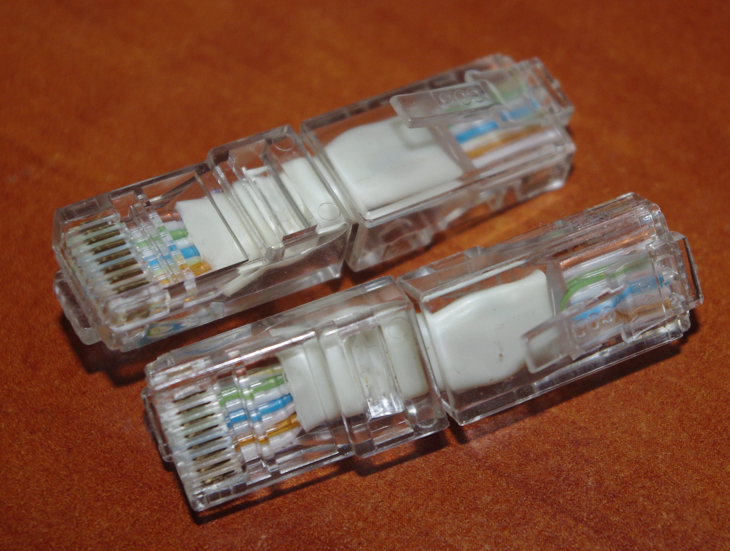
Click successively "Y", enter, enter, "openwrt-ramips-rt305x-a5-v11-squashfs-sysupgrade.bin". In the latter case, you will need to manually register the name of our firmware, which will need to be uploaded to a previously running tftp server. I used the TFTPD64 program for this purpose. After activating the console firmware download, you need to connect our A5-V11 with a computer whose IP address is the same as specified in the console. By the way, to connect directly (ala "usb-flash drive"), I made myself RJ45-RJ45 adapters. They are very convenient to carry along with the router.
The router will be flashed and after the reboot it will be ready to perform new combat missions. By the way, if it was not possible to flash the console, we return to the "programmatorona" of the article and sew the openwrt-ramips-rt305x-a5-v11-squashfs-sysupgrade.bin firmware through the good old AsProgrammer, not from the address 0, but from 327680 ( !)
Addition: you can not poke around with the search for bytes and modification of the native firmware, but fill the programmer with a new chip in the Chinese Breed loader from Comrade Hackpascal, for our V5, the last option found is breed-rt5350-hame-a5-r1163.bin . And already from this best (IMHO) to date, the loader to flash everything you need. There are still many goodies worthy of a separate article, BUT, but the damn firmware is absolutely no localization, in bare Chinese. It seems like technical terms are clear ... But "sediment remained." The Chinese, in principle, do not make contact: (
Part five, information ("note")
At the end of the story I would like to say a few words about the devices that make using our A5-V11 more comfortable.
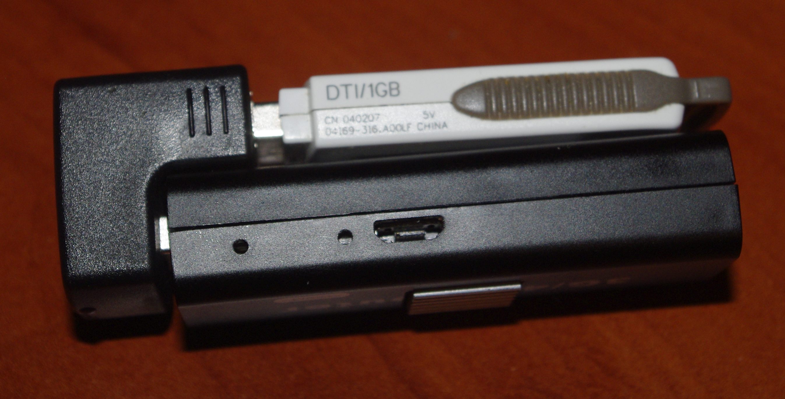
First of all, it is a U-shaped adapter to the USB port. An indispensable device when sharing a router with a USB flash drive / card reader / 3g-4g modem / SDR tuner finally :)
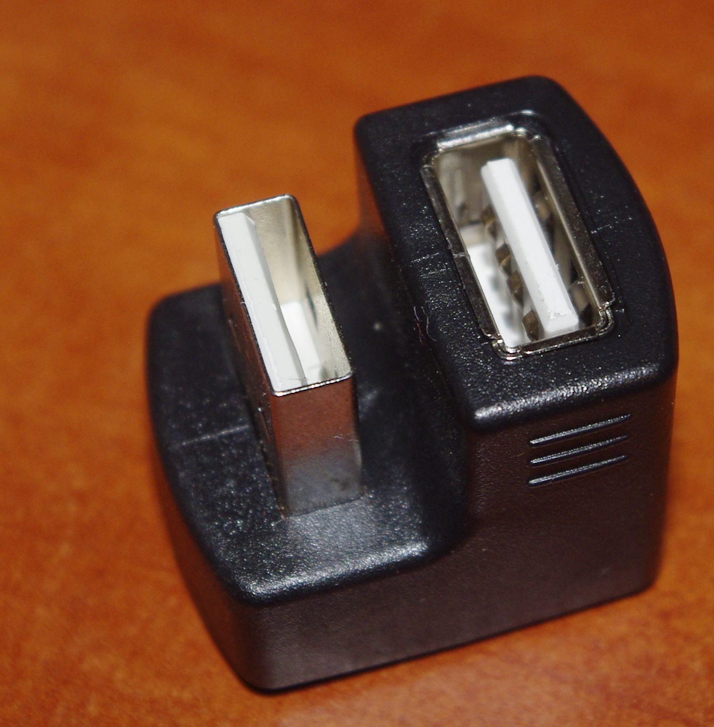
The second important milestone when working with the described mini-router is a USB hub. Yes, with a very difficult layout of USB ports. The vertical layout of this passive hub and pushes to buy a Bluetooth " fungus " on some CSR8510 . Since childhood, I like the concept of industrial PCs from Octagon - MicroPC - and their vertical PC / 104 “ sandwiches ”. There is an opportunity to do something similar with the said hub (by the way, if someone from the readers found something similar interesting on the Internet auction sites, please share in the comments).

On board the micro-chip GL8506 chip from Genesys Logic Inc.

In principle, instead of a vertical USB port, it is quite possible to place a small USB Bluetooth keychain described above or a microSD miniature card reader .

And this is what a ready-made "micro-sandwich sandwich" looks like :)


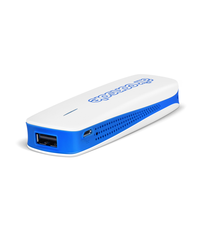
And finally, the most delicious. There is such a New Zealand office, CloudStore , known for its products under the Airconsole brand. These devices are good, among other things, because the only thing is absolutely legal and for reasonable money to connect various RS232 loggers to iOS. Very cool useful thing, including for the automation of old instruments and equipment controlled by RS232. I mentioned these cool devices and Habr .
And so they write about themselves :)
If you need to control remote equipment via COM / USB ports, then why spend hundreds or thousands of dollars on Moxa *, Perle * or Opengear * terminal servers? AirConsole has all the remote access and control capabilities for servers or network equipment, but is much more portable and consumes minimal power.
So, now attention. Below are some interesting pictures. As the saying goes, “find 10 differences” :)


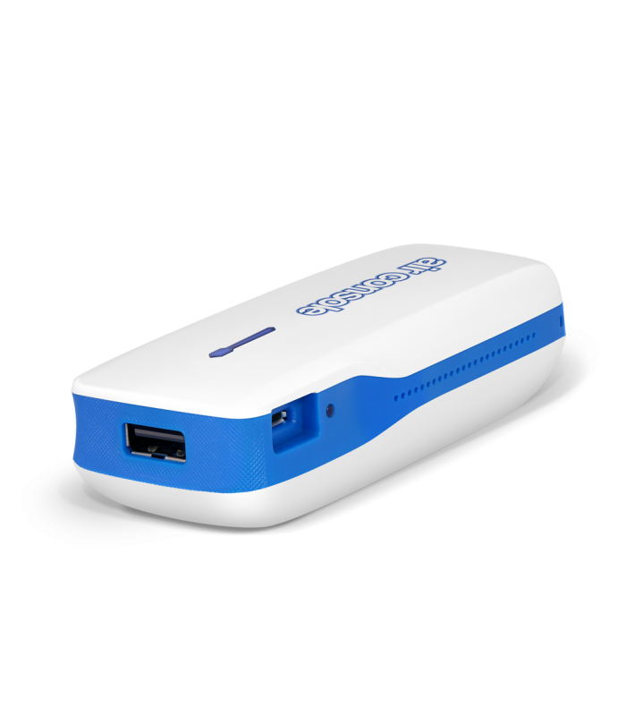
It intrigued me, and of course I honestly asked the manufacturer for their device to the test, but did not wait for an answer. I had to work by the method of mental experiment :) Well, read a little. As Henry Ford said, "The air is full of ideas. They constantly knock on your head. You just have to know what you want, then forget it and go about your business. The idea will come suddenly. It always has been ."
Therefore, in the net result, the answer is the following: “Chinese routers A5-V11 can be turned into Airconsole”. Here a glimpse of this issue was discussed and with the help of a dump fill, the guys turn their Hame for $ 6 into the Airconsole for $ 69. And rightly so, not Zyxel Keenetic 4G II as one alive enthusiast.
By the way, if suddenly among the readers there are owners of the original AirConsol, which have already opened them, I will gladly accept a gift of photo boards and add an article :)
Well, in principle, and all that I wanted to say. Much of what is written here is applicable for another (compact) hardware and I hope it will be useful for "a wide circle of readers" :)
Sergey Besarab ( Siarhei V. Besarab )
ps For the owners of the NEXX WT3020F, TP-Link TL-MR3020, TP-Link TL-WR703N (i.e., all routers with a rather spacious case) mentioned in the beginning of the article, the inexpensive hub on the HS8836 chip shown below can be a very convenient option for embedding :

Just in case, the scheme found here is shown under the spoiler.
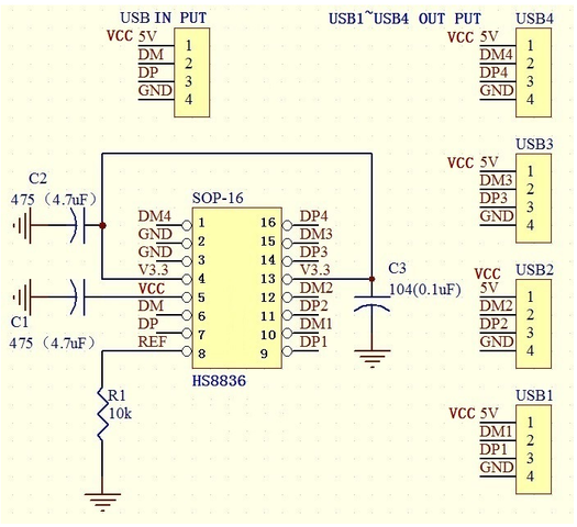
The main plus, in my opinion, in addition to the miniature size and the minimum of details is the mounting of the board with the controller and USB ports through the wires. For embedding in a router - a minimum of gestures, although you can still install an aluminum plate radiator on a chip.

Addition from 2019 : hands reached cooling by the walti method. Details under the spoiler

The first thing I found and cut a suitable aluminum plate with a thickness of 1 mm

Drilled holes for M1 screws and cut threads in the plate (especially waited for a tap on M1)


I tried to additionally tighten the nuts M1. I clung to my pocket, I didn’t like it, so I gave up on this idea and simply stole the protruding ends of the screws.

On the aluminum plate on the hot melt adhesive (mentioned in the article) I glued a copper plate 1.5 mm thick to the size of the crystal.

So that the screws do not short the router's handkerchief - closed them with a heat-resistant polyimide film

I put a piece of heat-conducting rubber on a copper plate (removed it from some laptop board) and assembled a router.

Heat transfer and flight are normal :).
- http://skproj.ru/hame-mpr-a1-proshivka-openwrt-i-apgrejd-fleshki-na-16-ili-8-megabajt/?doing_wp_cron=1472313516.0620179176330566406250
- http://w3bsit3-dns.com/forum/index.php?showtopic=884713&
- https://github.com/nofeletru/UsbAsp-flash/releases/
- http://forum.easyelectronics.ru/viewtopic.php?f=17&t=10947
- http://my-embedded.blogspot.com/2013/12/mini-4g-router-rt5350f.html
- http://eko.one.pl/?p=openwrt-gpio2
- https://habr.com/post/238713/
- https://nm-projects.de/2017/09/analysis-of-mini-3g4g-wifi-wireless-router-a5-v11/
- https://tuxotronic.org/wiki/tools/flashrom/
- http://srr.cherkessk.ru/owrt/help-owrt.html
- https://tuxotronic.org/wiki/openwrt/rt5350/build-firmware/
- https://mysku.ru/blog/aliexpress/27796.html
- https://habr.com/post/247513/
')
Source: https://habr.com/ru/post/425281/
All Articles