Developing a hexapod from scratch (part 2) - build
Hello! The time has come for the second part of the development of the SKYNET hexapod. In this article I will tell you how I assembled the case and about errors when designing it. There will also be a demonstration of the work of a limb and the first independent ascent from the belly.
ALARM: There will be a lot of pictures.

The case will differ slightly from the model from the first part, since the model is an improved version of the assembled case.
')
As mentioned in the first part , 3mm plywood will be used as the material. I made an order for laser cutting according to drawings from and after 2 days the model from the screen came over to my table, true in parts.
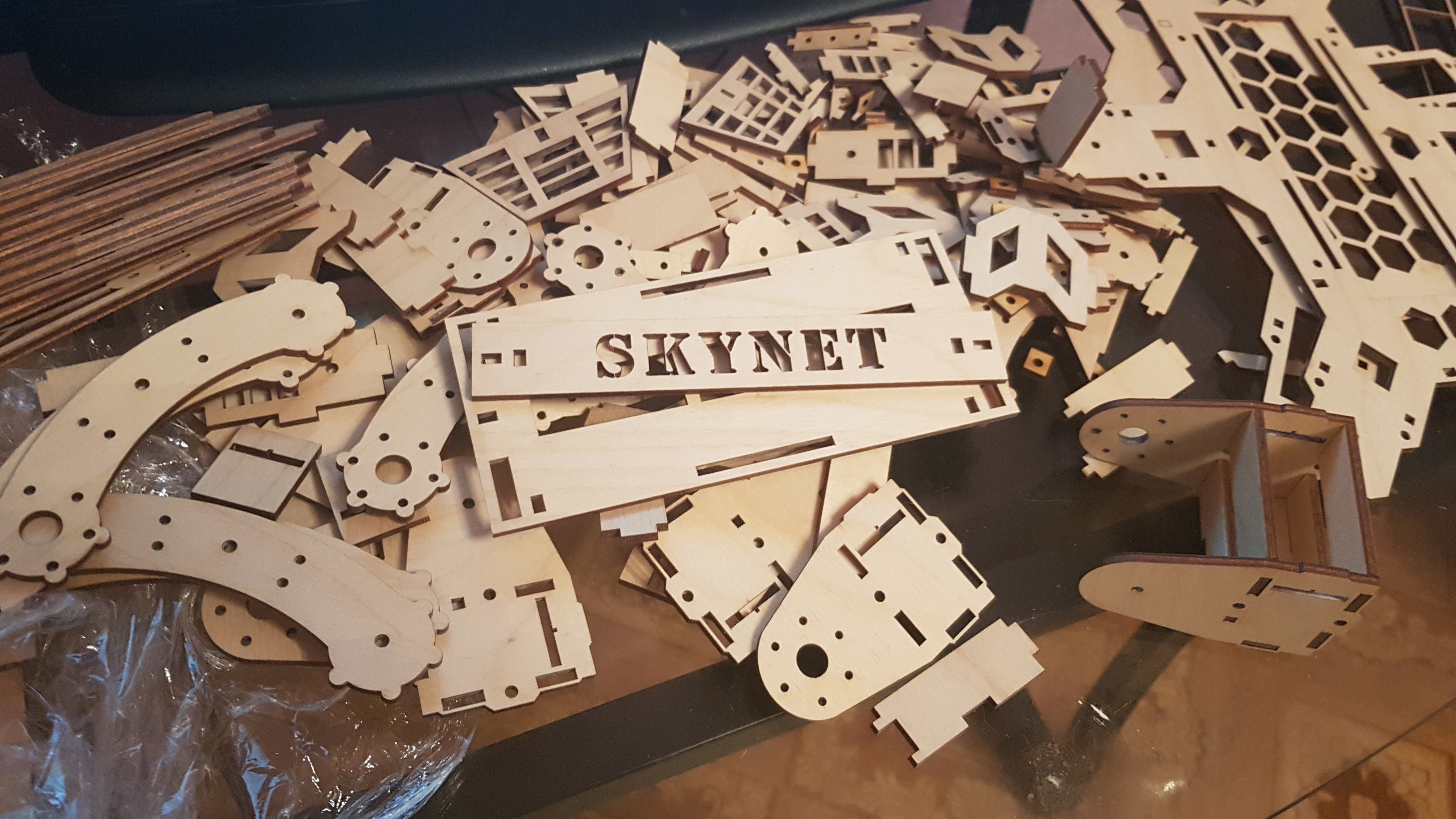
This did not stop me and a long assembly process began, which took about 3 to 4 hours. Before assembling, it is better to sort the parts, so it is much easier to assemble.

for (uint32_t i = 0; i <6; ++ i) {
I decided to start with the assembly of 1 link limb. This will require the following details:
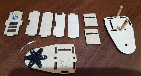
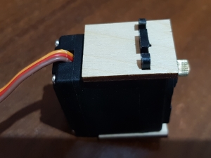
Oh yeah, we still need a servo. It is necessary to install 2 "pillows" on it, which will be fixed in the case. It is very difficult to confuse the sides; there is a special cutout in the pillows for a corner on the servo's ears.
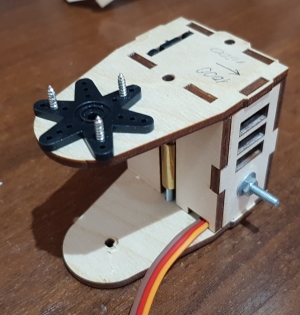
Next, put the resulting assembly on the lower part of the link in a special cutout and install the remaining parts in accordance with the model. The servo axis must align with the axis of the screw on the other side. Installation must be done very carefully without much effort, so as not to spoil the grooves. The result was the following:

In the end we put the upper part of the link, tighten the screws and the link is ready.
After absorbing a pair of cups of tea, it was time to assemble the second link. It looks easy to assemble, but this is the most routine part. For assembly, you will need the parts shown below. By the way, the most routine part has already been done - the rocking rods for the servos are screwed on. And yes, a little advice: fasten the screws fastest with pliers, while twisting the part itself.
Further assembly problems should not be. We do everything in accordance with the model and it should turn out like this:

Finally, we come to the last link of the future limb. We collect the necessary parts for the assembly in accordance with the model and begin the assembly of the frame:
Now we need a servo and pillows for it. Install them as follows (for the second ear of the servo do the same).
Next, install the servo in the frame and fasten it with screws. Also install the second part of the link and tighten all the screws. In this case, I decided to set the servo axis closer to the center of the link - it looks better.
Finally, the assembly of all the details of limb i is complete.
}
After completing the assembly cycle of parts of the limbs, you need to put everything together. I think the process of putting on rocking on the servo axis does not need to be described. It should turn out like this:

Video of one of the limbs:
This part is the easiest and I don’t need detailed comments. To assemble the frame we need all the remaining parts. I decided to start the assembly with the caps, since they are assembled with glue, and while I assemble the frame, the glue will dry out (hopefully).
Covers are going to be very simple and confusing there is something difficult. It should be like this (bottom cover):
As you can see, I filled with glue all the joints of the parts so that the whole structure does not fall apart. By the way, surprisingly, it was quite solid. The top cover is assembled similarly, only when it is assembled, the main thing is not to turn the name of the hexapod.
After assembling the covers, it is time to start assembling the frame. Servomotors are attached to the upper part on a straight line without pillows and tightened with my favorite screws and M3 nuts. Next, we put the wide and narrow racks in the grooves and cling the lower part. Then we tighten the whole thing with screws and rejoice in the result (do not laugh at the screwdriver, it has gone through a lot).
In the frame are the servos S3003, since the batch of MG996R of 6 pieces so far, that in the way, but they have the same dimensions.
After the frame is assembled, we install the covers into place, but they do not need to be glued. It looks cool.

And now the moment of truth - setting all legs into place. I think to install them on the axis of the servos is not difficult. The result is simply gorgeous:
Yes, he can get up. Joy at this moment was very much. The code was written on an early hand to see if he could even get up. In the assembly on the video, the S3003 servo drives are everywhere, since it was shot before the transition to the MG996R.
In the following articles I plan to tell you about the electronics of the robot and its basic mathematics.
ALARM: There will be a lot of pictures.
The case will differ slightly from the model from the first part, since the model is an improved version of the assembled case.
')
As mentioned in the first part , 3mm plywood will be used as the material. I made an order for laser cutting according to drawings from and after 2 days the model from the screen came over to my table, true in parts.
This did not stop me and a long assembly process began, which took about 3 to 4 hours. Before assembling, it is better to sort the parts, so it is much easier to assemble.
Limb assembly
for (uint32_t i = 0; i <6; ++ i) {
Link 1
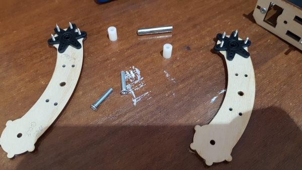
I decided to start with the assembly of 1 link limb. This will require the following details:
Oh yeah, we still need a servo. It is necessary to install 2 "pillows" on it, which will be fixed in the case. It is very difficult to confuse the sides; there is a special cutout in the pillows for a corner on the servo's ears.
Next, put the resulting assembly on the lower part of the link in a special cutout and install the remaining parts in accordance with the model. The servo axis must align with the axis of the screw on the other side. Installation must be done very carefully without much effort, so as not to spoil the grooves. The result was the following:
In the end we put the upper part of the link, tighten the screws and the link is ready.
Link 2
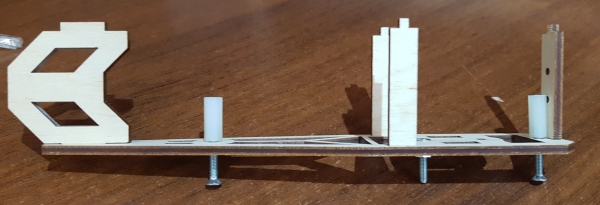
After absorbing a pair of cups of tea, it was time to assemble the second link. It looks easy to assemble, but this is the most routine part. For assembly, you will need the parts shown below. By the way, the most routine part has already been done - the rocking rods for the servos are screwed on. And yes, a little advice: fasten the screws fastest with pliers, while twisting the part itself.
Further assembly problems should not be. We do everything in accordance with the model and it should turn out like this:
Link 3
Finally, we come to the last link of the future limb. We collect the necessary parts for the assembly in accordance with the model and begin the assembly of the frame:
Now we need a servo and pillows for it. Install them as follows (for the second ear of the servo do the same).
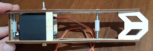
Next, install the servo in the frame and fasten it with screws. Also install the second part of the link and tighten all the screws. In this case, I decided to set the servo axis closer to the center of the link - it looks better.
Finally, the assembly of all the details of limb i is complete.
}
After completing the assembly cycle of parts of the limbs, you need to put everything together. I think the process of putting on rocking on the servo axis does not need to be described. It should turn out like this:
Video of one of the limbs:
Frame assembly
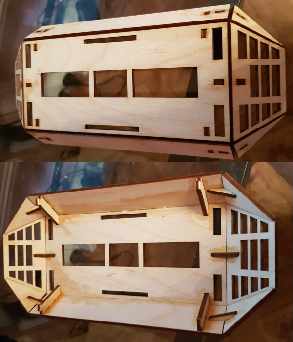
This part is the easiest and I don’t need detailed comments. To assemble the frame we need all the remaining parts. I decided to start the assembly with the caps, since they are assembled with glue, and while I assemble the frame, the glue will dry out (hopefully).
Covers are going to be very simple and confusing there is something difficult. It should be like this (bottom cover):
As you can see, I filled with glue all the joints of the parts so that the whole structure does not fall apart. By the way, surprisingly, it was quite solid. The top cover is assembled similarly, only when it is assembled, the main thing is not to turn the name of the hexapod.
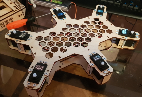
After assembling the covers, it is time to start assembling the frame. Servomotors are attached to the upper part on a straight line without pillows and tightened with my favorite screws and M3 nuts. Next, we put the wide and narrow racks in the grooves and cling the lower part. Then we tighten the whole thing with screws and rejoice in the result (do not laugh at the screwdriver, it has gone through a lot).
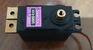
In the frame are the servos S3003, since the batch of MG996R of 6 pieces so far, that in the way, but they have the same dimensions.
After the frame is assembled, we install the covers into place, but they do not need to be glued. It looks cool.
Result
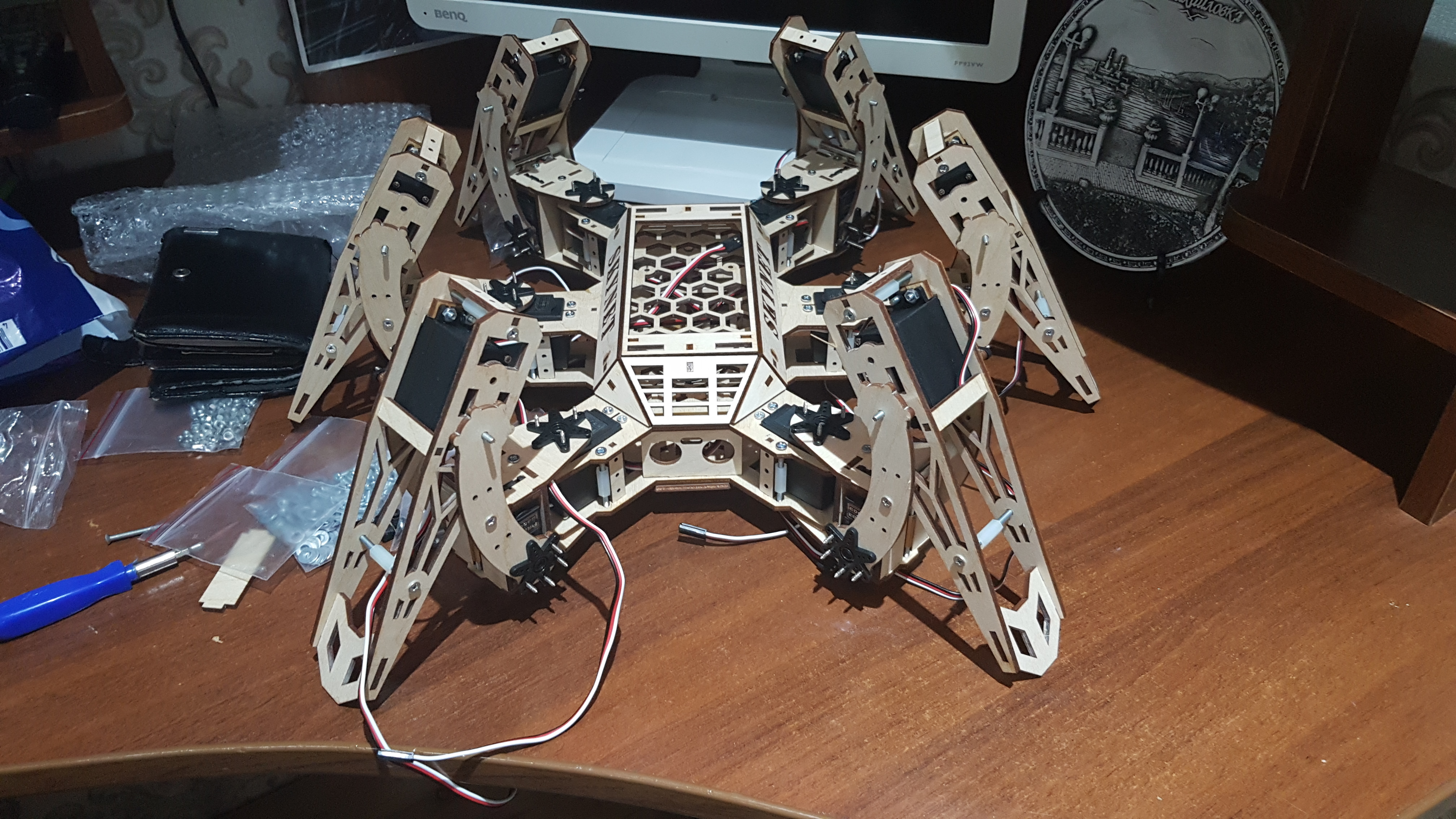
And now the moment of truth - setting all legs into place. I think to install them on the axis of the servos is not difficult. The result is simply gorgeous:
Yes, he can get up. Joy at this moment was very much. The code was written on an early hand to see if he could even get up. In the assembly on the video, the S3003 servo drives are everywhere, since it was shot before the transition to the MG996R.
Rakes, choppers and hoes that I stepped on
- Servos. I decided to take the cheapest S3003 for 100 rubles for a joke and regretted it. Effort is enough with a margin, but the backlash is terrible. The servo axis can be safely rotated about 10 degrees in any direction, and it does not make any attempts to hold the position. If you twist more, it will resist. And no smooth movements with them can not be realized.
- Wrong location of supports. As a result of this, in some places the parts sag when tightened, this is especially noticeable on the 3 link of the limb.
- The larger the piece of plywood, the more it is deformed, especially in the frame. As a result, some places have cracks.
Solution: added a pair of screw holes at the edges
- Bearings. Yes, it was necessary to put the bearings. This hoe did not strike the leg yet, but I feel that it is approaching. Axial holes quickly izotrutsya under load and will play.
Plans
In the following articles I plan to tell you about the electronics of the robot and its basic mathematics.
Source: https://habr.com/ru/post/424905/
All Articles