Minidrill speed controller
The drilling of printed circuit boards is a real headache for the electronics engineer, but our new device will help soften it a bit. This simple and compact addition to the mini-drill will extend the life of the engine and drills. Scheme, fee, instructions for setting up, video - all in the article!
Usually mini-drills are built on the basis of conventional DC motors. And the speed of such engines depends on the load and the applied voltage. As a result, at idle speed the engine spins up very strongly, and at the moments of drilling the engine revolutions float in a large range.
If you reduce the voltage on the engine, when there is no load on it, you can increase the service life of both the drills and the engines themselves. In addition, even drilling accuracy is improved. The easiest way to achieve this is to measure the current consumed by the motor.
')
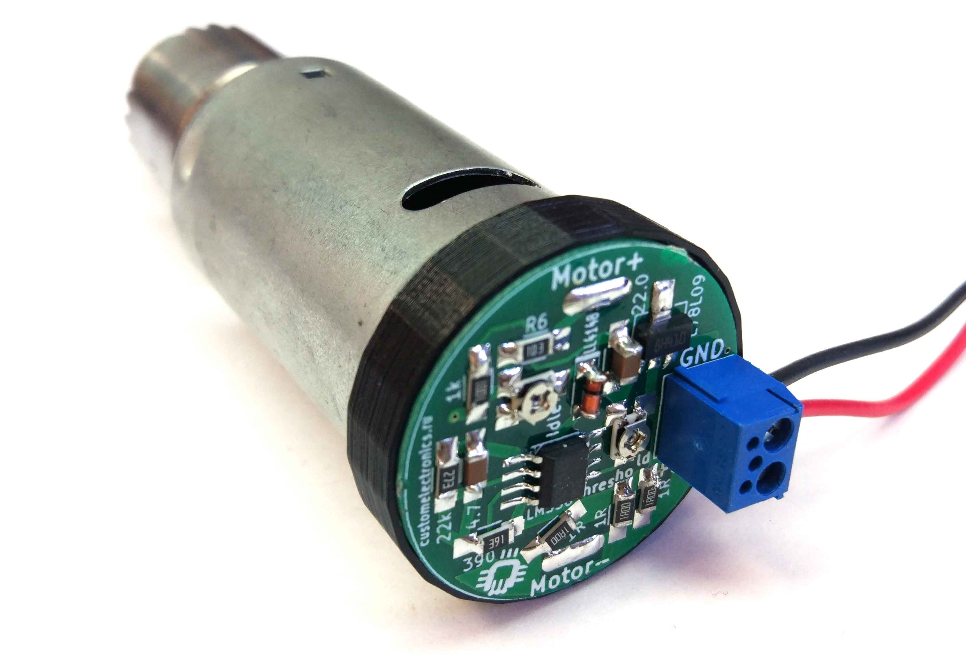
There are many schemes of similar regulators on the Internet, but most of them use linear voltage regulators. They are massive and require cooling. In collaboration with TinyElectronicFriends, we wanted to make a compact board based on a switching regulator so that it could be simply “worn” on the engine.
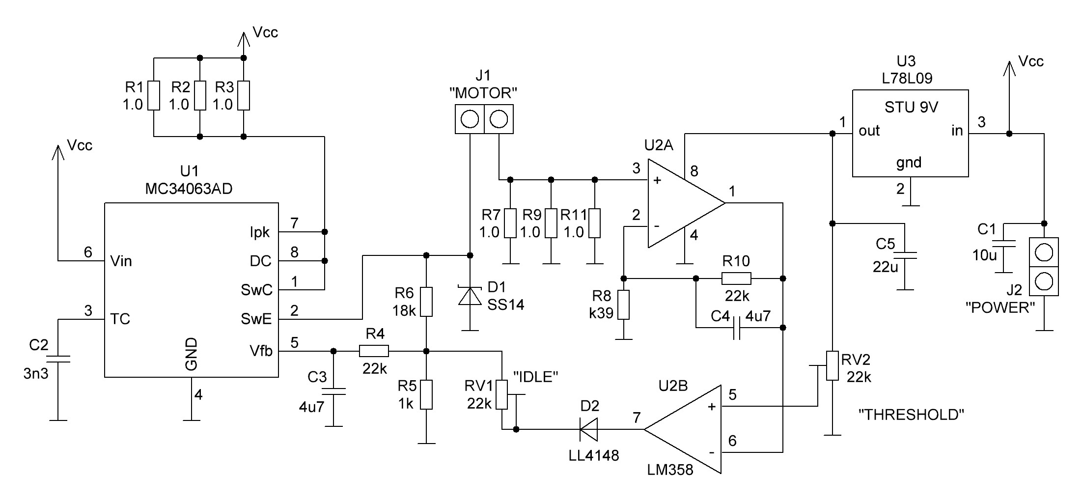
A PWM controller with an integrated key MC34063 regulates the voltage on the motor. The voltage on the shunt R7, R9, R11 is amplified by the operational amplifier and through the comparator is fed to the input of the feedback PWM controller.
If the current is less than a certain value, a voltage is applied to the motor, depending on the resistance setting RV1. That is, at idle speed, only a part of the power will be supplied to the engine, and the trimming resistor RV1 will allow adjusting the rpm.
If the signal at the output of the op-amp exceeds the voltage on the comparator, the full supply voltage will be applied to the engine. That is, when drilling the engine will turn on at maximum power. The switching threshold is set by the RV2 resistor.
A linear stabilizer is used to power the op amp.
All components of the circuit will dissipate very little heat and you can assemble it completely on SMD components. It can work with a large range of supply voltages (depending on the resistance R6), does not require controllers and speed sensors.
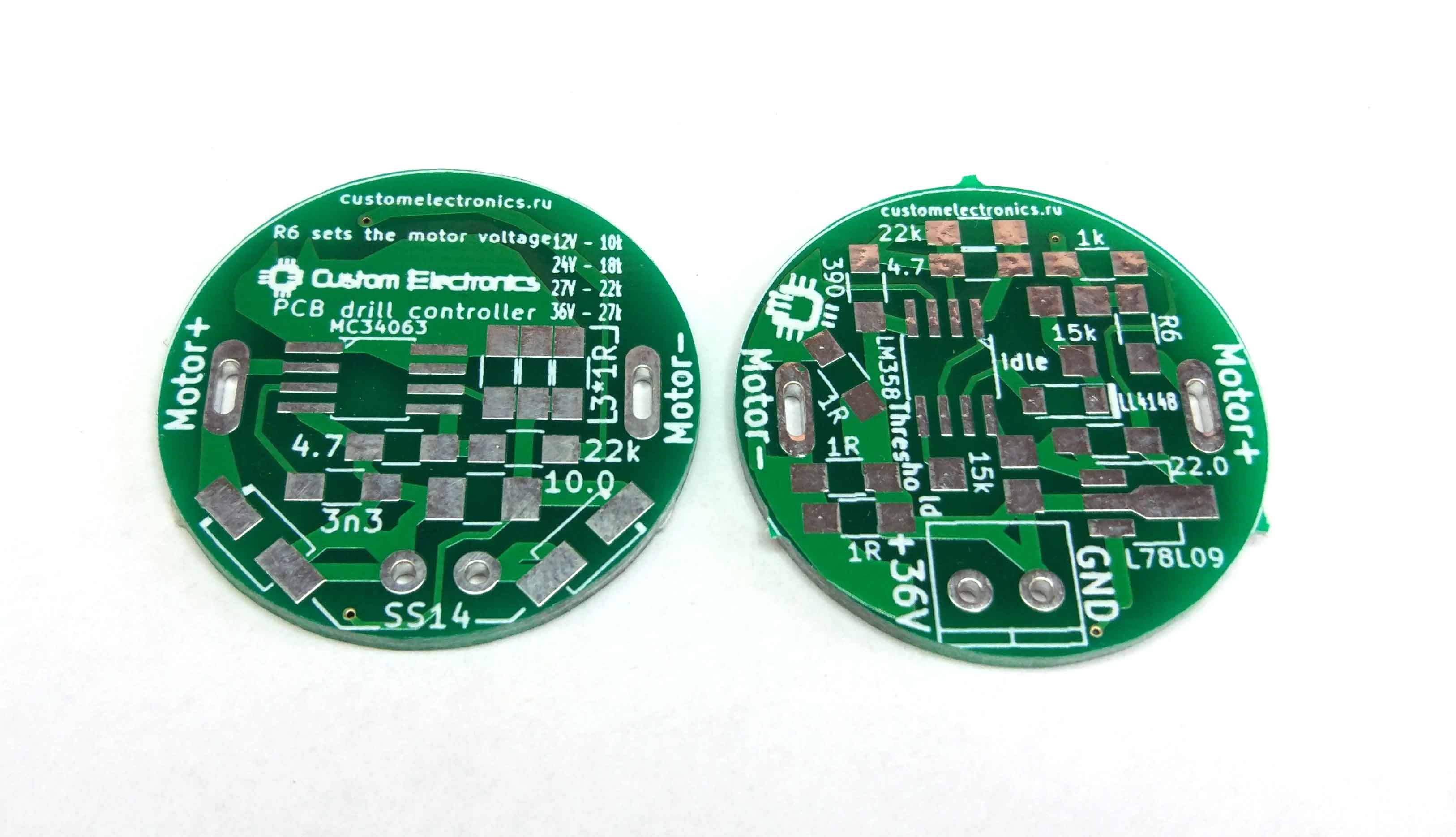
The whole scheme fits on a double-sided printed circuit board with a diameter of 30mm. There are only a few pieces of vias on it and it can be easily made “at home”. Below in the article there will be files for downloading the PCB file for SprintLaout.
Here is a complete list of everything you need to build:
We also made a 3D limiter ring on the 3D printer, for convenient installation on the engine. Link to download the STL file for download at the end of the article.

Everything is going to be quite simple. Contact pads are drawn by hand soldering.
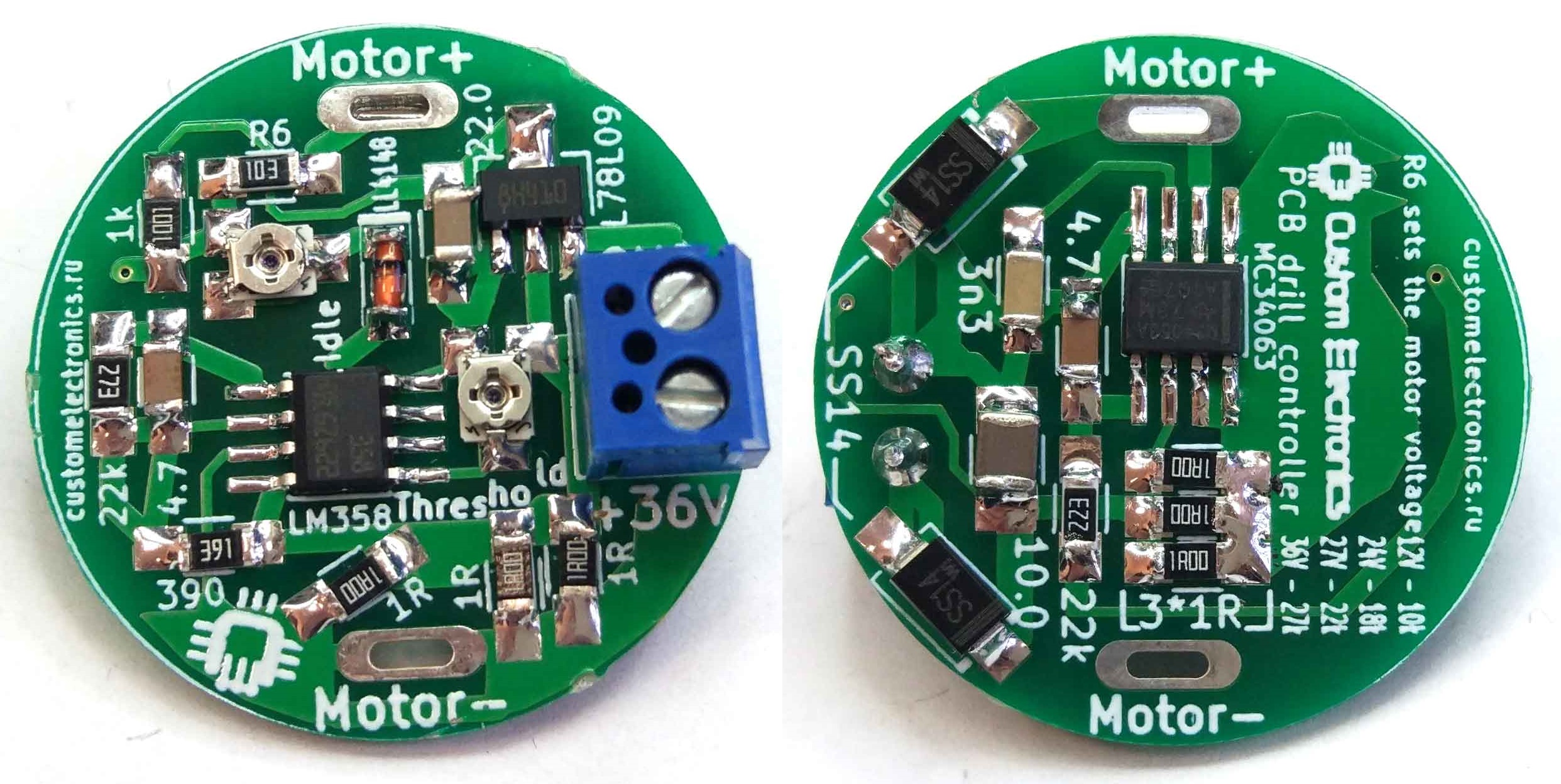
It is worth starting the assembly of the board itself with the installation of all the components on the side of the board without trimmers, and then on the reverse side. The terminal is easier to install last. R6 is rated according to the rated voltage of your motor. In this device it is important to control the position of the key on the chips and the polarity of the diodes. All other components are not polar.
Install a spacer between the board and the engine so that the board does not touch the engine. The board itself is worn directly on the engine's slats. Check the polarity of the motor several times so that it turns to the right side, and then solder the contacts.
Contacts for voltage supply, at the input of the board are signed "GND" and "+ 36V". The minus of the input voltage source is connected to the “GND” terminal, and the plus to “+ 36V”. The power supply voltage must match the rated motor voltage.
Setting the controller is very simple:
The effect of use is difficult to assess from the video, but now we always drill only with the regulator! It takes only a little getting used to and follow to the drill was well sharpened. And, of course, you can at any time simply turn it on to a maximum for always.
Links to download all the necessary files you can find on the main page of the project .
Thank you for your interest!
Why do we need a speed controller
Usually mini-drills are built on the basis of conventional DC motors. And the speed of such engines depends on the load and the applied voltage. As a result, at idle speed the engine spins up very strongly, and at the moments of drilling the engine revolutions float in a large range.
If you reduce the voltage on the engine, when there is no load on it, you can increase the service life of both the drills and the engines themselves. In addition, even drilling accuracy is improved. The easiest way to achieve this is to measure the current consumed by the motor.
')
There are many schemes of similar regulators on the Internet, but most of them use linear voltage regulators. They are massive and require cooling. In collaboration with TinyElectronicFriends, we wanted to make a compact board based on a switching regulator so that it could be simply “worn” on the engine.
Scheme
A PWM controller with an integrated key MC34063 regulates the voltage on the motor. The voltage on the shunt R7, R9, R11 is amplified by the operational amplifier and through the comparator is fed to the input of the feedback PWM controller.
If the current is less than a certain value, a voltage is applied to the motor, depending on the resistance setting RV1. That is, at idle speed, only a part of the power will be supplied to the engine, and the trimming resistor RV1 will allow adjusting the rpm.
If the signal at the output of the op-amp exceeds the voltage on the comparator, the full supply voltage will be applied to the engine. That is, when drilling the engine will turn on at maximum power. The switching threshold is set by the RV2 resistor.
A linear stabilizer is used to power the op amp.
All components of the circuit will dissipate very little heat and you can assemble it completely on SMD components. It can work with a large range of supply voltages (depending on the resistance R6), does not require controllers and speed sensors.
Printed circuit board
The whole scheme fits on a double-sided printed circuit board with a diameter of 30mm. There are only a few pieces of vias on it and it can be easily made “at home”. Below in the article there will be files for downloading the PCB file for SprintLaout.
List of components
Here is a complete list of everything you need to build:
- Printed circuit board (link to files for manufacturing at the end of the article)
- U1 - MC34063AD, switching regulator, SOIC-8
- U2 - LM358, operational amplifier, SOIC-8
- U3 - L78L09 stabilizer, SOT-89
- D1, D3 - SS14, Schottky diode, SMA - 2pcs
- D2 - LL4148, Rectifying Diode, MiniMELF
- C1 - capacitor, 10µF, 50V, 1210
- C2 - capacitor, 3.3nF, 1206
- C3, C4 - capacitor, 4.7µF, 1206 - 2 pcs
- C5 - capacitor, 22µF, 1206
- R1-R3, R7, R9, R11 - 1 Ohm resistor, 1206 - 6 pcs
- R4, R10 - 22kΩ resistor, 1206 - 2pcs
- R5 - 1kΩ resistor, 1206
- R6 - resistor 10-27kOhm, 1206. Resistance depends on the rated voltage of the motor used. 12V - 10kohm, 24V - 18kohm, 27V - 22kohm, 36V - 27kohm
- R8 - 390 ohm resistor, 1206
- RV1, RV2 - resistor subscript, 15kΩ, type 3224W-1-153 - 2 pcs
- XS1 - terminal, 2 pin, pitch 3.81mm
We also made a 3D limiter ring on the 3D printer, for convenient installation on the engine. Link to download the STL file for download at the end of the article.
Build and configure
Everything is going to be quite simple. Contact pads are drawn by hand soldering.
It is worth starting the assembly of the board itself with the installation of all the components on the side of the board without trimmers, and then on the reverse side. The terminal is easier to install last. R6 is rated according to the rated voltage of your motor. In this device it is important to control the position of the key on the chips and the polarity of the diodes. All other components are not polar.
Install a spacer between the board and the engine so that the board does not touch the engine. The board itself is worn directly on the engine's slats. Check the polarity of the motor several times so that it turns to the right side, and then solder the contacts.
Contacts for voltage supply, at the input of the board are signed "GND" and "+ 36V". The minus of the input voltage source is connected to the “GND” terminal, and the plus to “+ 36V”. The power supply voltage must match the rated motor voltage.
Setting the controller is very simple:
- Set the resistor RV2 threshold regulator to maximum
- Set the RV1 resistor to the optimum engine speed in idle mode
- Set the RV2 resistor to such an operating threshold so that when the slightest load appears, the voltage on the motor increases
Video
The effect of use is difficult to assess from the video, but now we always drill only with the regulator! It takes only a little getting used to and follow to the drill was well sharpened. And, of course, you can at any time simply turn it on to a maximum for always.
Links
Links to download all the necessary files you can find on the main page of the project .
Thank you for your interest!
Source: https://habr.com/ru/post/424525/
All Articles