Cards from hexagons in Unity: bumps, rivers and roads
Parts 1-3: mesh, cell colors and heights
Parts 4-7: bumps, rivers and roads
')
Parts 8-11: water, landforms and walls
Parts 12-15: saving and loading, textures, distances
Parts 16-19: Pathfinding, Player Squads, Animations
Parts 20-23: fog of war, map exploration, procedural generation
Parts 24-27: water cycle, erosion, biomes, cylindrical map
Part 4: Irregularities
Table of contents
- Sample the noise texture.
- Move the vertices.
- Keep the cells flat.
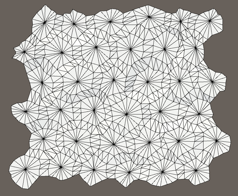
- We subdivide the edges of the cells.
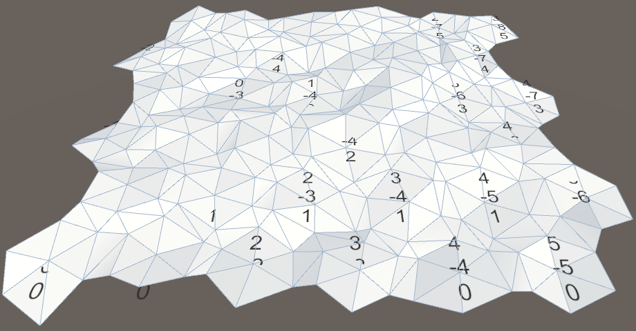
While our grid was a strict pattern of honeycombs. In this part, we will add bumps to make the map look more natural.
No more flat hexagons.
Noise
To add bumps, we need randomization, but not true randomness. We want everything to remain consistent when changing the map. Otherwise, when you make any changes, the objects will jump. That is, we need some form of reproducible pseudo-random noise.
A good candidate is Perlin's noise. It is reproducible at any point. When combining several frequencies, it also creates noise, which can vary greatly over long distances, but remains almost the same at short distances. This makes it possible to create relatively smooth distortion. Nearby points usually stay close together and are not scattered in opposite directions.
We can generate Perlin noise programmatically. In the Noise tutorial, I explain how to do this. But we can also sample from the pre-generated noise texture. The advantage of using a texture is that it is simpler and much faster than the calculation of the multi-frequency Perlin noise. Its disadvantage is that the texture takes up more memory and covers only a small area of noise. Therefore, it must be seamlessly connected and large enough so that the repetitions are not conspicuous.
Noise texture
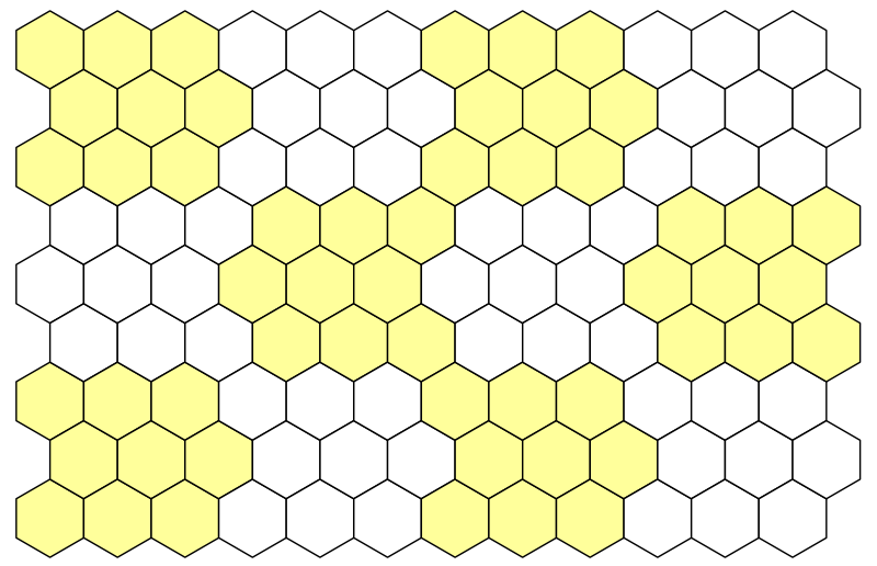
We will use the texture, so you will not need to study the Noise tutorial. So we need a texture. Here she is:
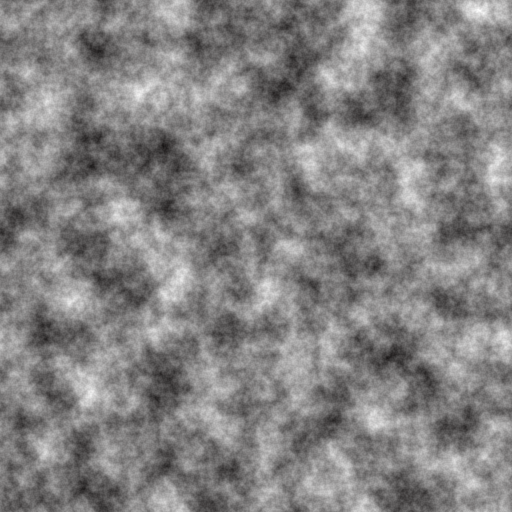
Seamlessly connected texture of Perlin noise.
The texture shown above contains Perlin's seamlessly interconnected multi-frequency noise. This is a grayscale image. Its average value is 0.5, and the extreme values tend to 0 and 1.
But wait, each point has only one value. If we need three-dimensional distortion, then we need at least three pseudo-random samples! Therefore, we need two more textures with different noise.
We can create them or store different noise values in each of the color channels. This will allow us to store up to four noise patterns in one texture. Here is the texture.
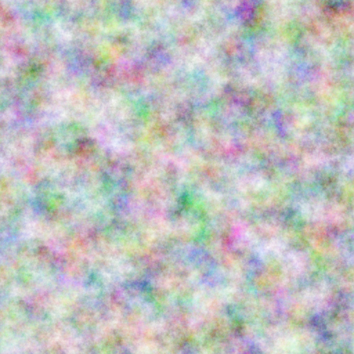
Four in one.
How to create such a texture?
I used NumberFlow . This is my procedural texture editor for Unity.
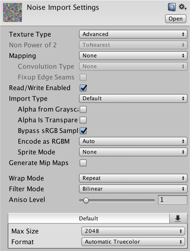
Download this texture and import it into the Unity project. Since we are going to sample the texture through the code, it should be readable. Switch Texture Type to Advanced and enable Read / Write Enabled . This will save the texture data in memory and can be accessed from C # code. Set the Format to Automatic Truecolor , otherwise it will not work. We don't want texture compression to destroy our noise pattern.
You can disable Generate Mip Maps , because we do not need them. Also enable Bypass sRGB Sampling . We will not need this, but it will be right. This parameter means that the texture does not contain color data in gamma space.
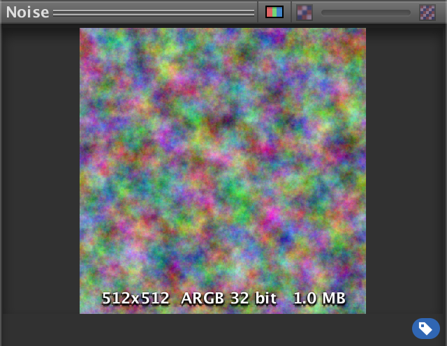
Imported noise texture.
When is sRGB sampling important?
If we wanted to use the texture in the shader, this would be important. When using the Linear rendering mode, texture sampling automatically converts color data from the gamma to a linear color space. In the case of our noise texture, this will lead to incorrect results, so we do not need this.
Why do my texture import settings look different?
They were changed after this tutorial was written. You need to use the default 2D texture settings, sRGB (Color Texture) should be disabled, and Compression should be set to None .
Noise sampling
Let's add
HexMetrics noise sampling functionality so that you can use it anywhere. This means that HexMetrics should contain a link to the noise texture. public static Texture2D noiseSource; Since this is not a component, we cannot assign a texture to it through the editor. Therefore, we use
HexGrid as an intermediary. Since HexGrid will act first, it will be quite normal if we pass the texture at the beginning of its Awake method. public Texture2D noiseSource; void Awake () { HexMetrics.noiseSource = noiseSource; … } However, this approach will not survive the replay in Play mode. Static variables are not serialized by the Unity engine. To solve this problem, reassign the texture to the
OnEnable event OnEnable . This method will be called after recompilation. void OnEnable () { HexMetrics.noiseSource = noiseSource; } 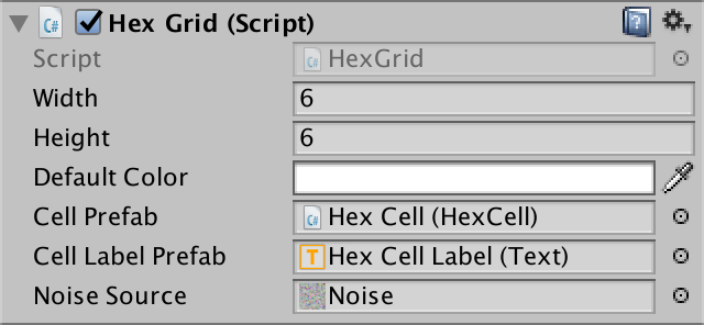
Assign a noise texture.
Now that
HexMetrics has access to the texture, let's add a convenient noise sampling method to it. This method gains a position in the world and creates a 4D vector containing four noise samples. public static Vector4 SampleNoise (Vector3 position) { } Samples are created by texture sampling using bilinear filtering, in which the X and Z world coordinates were used as UV coordinates. Since our noise source is two-dimensional, we ignore the third coordinate of the world. If the noise source was three-dimensional, we would use the Y coordinate.
As a result, we get a color that can be converted into a 4D vector. Such a cast may be indirect, that is, we can return the color directly, not including explicitly
(Vector4) . public static Vector4 SampleNoise (Vector3 position) { return noiseSource.GetPixelBilinear(position.x, position.z); } How does bilinear filtering work?
For explanations of UV coordinates and filtering textures, see Rendering 2, Shader Fundamentals .
unitypackage
Moving vertices
We will distort our flat grid of cells, individually moving each of the vertices. To do this, let's add
HexMesh to Perturb . It takes the unplaced point and returns the displaced. To do this, it uses the unbiased point when sampling noise. Vector3 Perturb (Vector3 position) { Vector4 sample = HexMetrics.SampleNoise(position); } Let's just add samples of noise X, Y and Z directly with the corresponding coordinates of the point and use this as a result.
Vector3 Perturb (Vector3 position) { Vector4 sample = HexMetrics.SampleNoise(position); position.x += sample.x; position.y += sample.y; position.z += sample.z; return position; } How do we quickly change
HexMesh to move all the vertices? Changing each vertex when adding to the list of vertices in the AddTriangle and AddQuad . Let's do it. void AddTriangle (Vector3 v1, Vector3 v2, Vector3 v3) { int vertexIndex = vertices.Count; vertices.Add(Perturb(v1)); vertices.Add(Perturb(v2)); vertices.Add(Perturb(v3)); … } void AddQuad (Vector3 v1, Vector3 v2, Vector3 v3, Vector3 v4) { int vertexIndex = vertices.Count; vertices.Add(Perturb(v1)); vertices.Add(Perturb(v2)); vertices.Add(Perturb(v3)); vertices.Add(Perturb(v4)); … } Will quadrangles remain flat after moving their vertices?
Most likely no. They consist of two triangles that will no longer lie in the same plane. However, since these triangles have two common vertices, the normals of these vertices will be smoothed. This means that we will not have sharp transitions between two triangles. If the distortion is not too large, then we will still perceive quadrangles as flat.
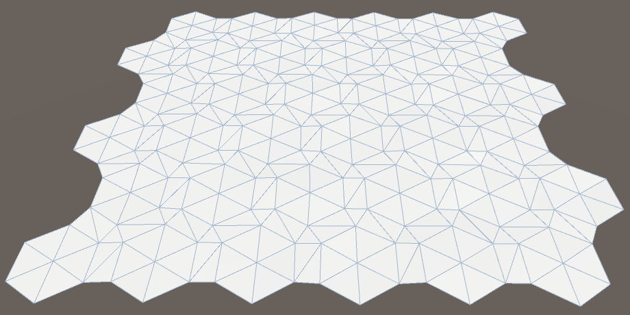
Vertices either moved or not.
While the changes are not very noticeable, only the labels of the cells are gone. This happened because we added noise to samples, and they are always positive. Therefore, as a result, all the triangles have risen above their marks, closing them. We need to center the changes so that they occur in both directions. Change the interval of the noise sample from 0–1 to −1–1.
Vector3 Perturb (Vector3 position) { Vector4 sample = HexMetrics.SampleNoise(position); position.x += sample.x * 2f - 1f; position.y += sample.y * 2f - 1f; position.z += sample.z * 2f - 1f; return position; } 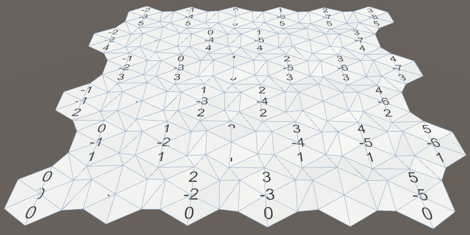
Centered displacement.
The magnitude (force) of movement
Now it is obvious that we have distorted the grid, but the effect is barely noticeable. The change in each dimension is no more than 1 unit. That is, the theoretical maximum displacement is √3 ≈ 1.73 units, which will occur extremely rarely, if at all. Since the outer radius of the cells is 10 units, the displacements are relatively small.
The solution is to add a
HexMetrics parameter to HexMetrics so that the displacements can be scaled. Let's try using force 5. At the same time, the theoretical maximum offset will be √75 ≈ 8.66 units, which is much more noticeable. public const float cellPerturbStrength = 5f; We apply force, multiplying it by samples in
HexMesh.Perturb . Vector3 Perturb (Vector3 position) { Vector4 sample = HexMetrics.SampleNoise(position); position.x += (sample.x * 2f - 1f) * HexMetrics.cellPerturbStrength; position.y += (sample.y * 2f - 1f) * HexMetrics.cellPerturbStrength; position.z += (sample.z * 2f - 1f) * HexMetrics.cellPerturbStrength; return position; } 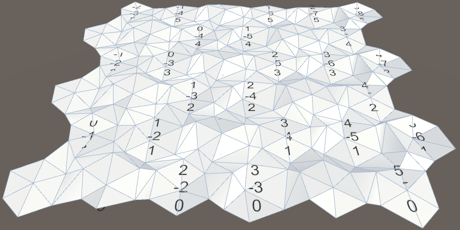
Increased strength.
Noise scale
Although the grid looks good before the change, things can go wrong after the steps appear. Their tops can be distorted in unpredictably different directions, creating chaos. When using Perlin noise, this should not happen.
The problem arises because we directly use the coordinates of the world to sample the noise. Because of this, the texture is hidden through each unit, and the cells are much larger than this value. In fact, the texture is sampled at arbitrary points, destroying the integrity it has.
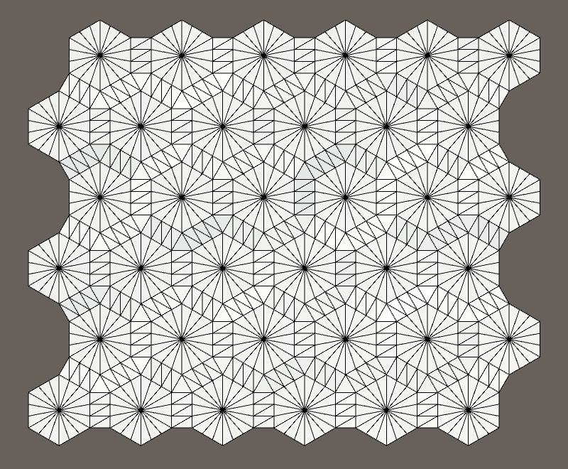
Grid rows 10 by 10 overlap cells.
We will have to scale the noise sampling so that the texture covers a much larger area. Let's add this scale to
HexMetrics and assign it a value of 0.003, and then scale the coordinates of the samples by this factor. public const float noiseScale = 0.003f; public static Vector4 SampleNoise (Vector3 position) { return noiseSource.GetPixelBilinear( position.x * noiseScale, position.z * noiseScale ); } Suddenly, it turns out that our texture covers 333 & frac13; square units, and its local integrity becomes apparent.
Scaled noise.
In addition, the new scale increases the distance between the noise junctions. In fact, since the cells have an inner diameter of 10√3 units, it will never exactly hide in dimension X. However, due to the local integrity of the noise, on a larger scale, we will still be able to recognize repeated patterns approximately every 20 cells, even if the details do not match. But they will be obvious only on the map without other features.
unitypackage
Align Cell Centers
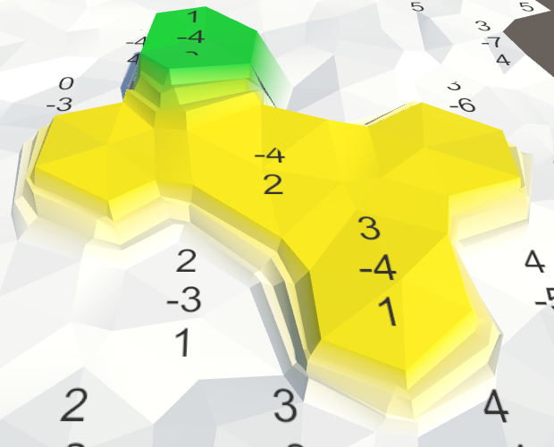
Moving all the vertices gives the map a more natural look, but several problems arise. Since the cells are now uneven, their labels intersect with the mesh. And in the joints of the ledges with cliffs cracks occur. We will leave the cracks for later, and now we will concentrate on the surfaces of the cells.
The map has become less strict, but more problems have appeared.
The simplest solution to the intersection problem is to make the cell centers flat. Let's just not change the Y coordinate in
HexMesh.Perturb . Vector3 Perturb (Vector3 position) { Vector4 sample = HexMetrics.SampleNoise(position); position.x += (sample.x * 2f - 1f) * HexMetrics.cellPerturbStrength; // position.y += (sample.y * 2f - 1f) * HexMetrics.cellPerturbStrength; position.z += (sample.z * 2f - 1f) * HexMetrics.cellPerturbStrength; return position; } 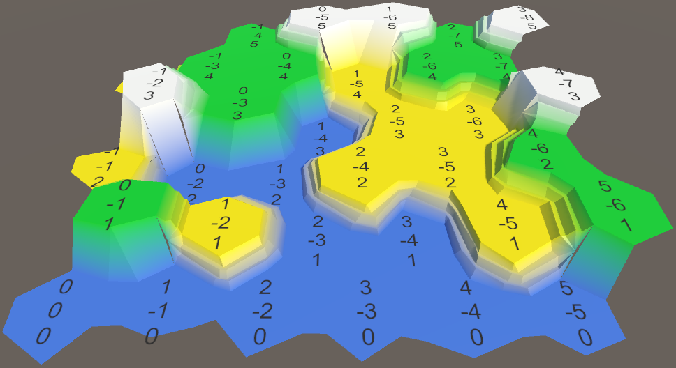
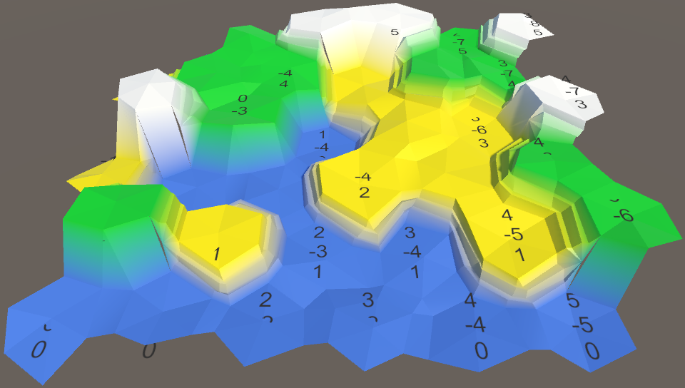
Aligned cells.
With this change, all vertical positions will remain unchanged, both at the centers of the cells and at the steps of the ledges. It should be noted that this reduces the maximum displacement to √50 ≈ 7.07 only in the XZ plane.
This is a nice change, because it simplifies the identification of individual cells and prevents the ledges from becoming too chaotic. But it would still be nice to add a small vertical movement.
Moving cell height
Instead of applying vertical movement to each vertex, we can apply it to the cell. In this case, each cell will remain flat, but the variation between the cells will still remain. It would also be logical to use a different scale to move the height, so add it to
HexMetrics . The strength of 1.5 units creates a small variation, approximately equal to the height of one step of the ledge. public const float elevationPerturbStrength = 1.5f; HexCell.Elevation property so that it HexCell.Elevation this move to the vertical position of the cell. public int Elevation { get { return elevation; } set { elevation = value; Vector3 position = transform.localPosition; position.y = value * HexMetrics.elevationStep; position.y += (HexMetrics.SampleNoise(position).y * 2f - 1f) * HexMetrics.elevationPerturbStrength; transform.localPosition = position; Vector3 uiPosition = uiRect.localPosition; uiPosition.z = -position.y; uiRect.localPosition = uiPosition; } } In order for the move to be applied immediately, we need to explicitly set the height of each cell in the
HexGrid.CreateCell . HexGrid.CreateCell . Otherwise, the mesh will initially be flat. We do this at the end, after creating the UI. void CreateCell (int x, int z, int i) { … cell.Elevation = 0; } 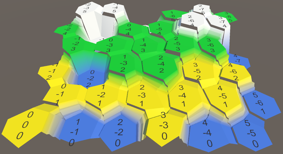
Moved heights with cracks.
Use the same heights
Many cracks appeared in the mesh, because we do not use the same cell heights during the mesh triangulation. Let's add a property to
HexCell to get its position so that you can use it anywhere. public Vector3 Position { get { return transform.localPosition; } } Now we can use this property in
HexMesh.Triangulate to determine the center of the cell. void Triangulate (HexDirection direction, HexCell cell) { Vector3 center = cell.Position; … } And we can use it in
TriangulateConnection when determining the vertical positions of neighboring cells. void TriangulateConnection ( HexDirection direction, HexCell cell, Vector3 v1, Vector3 v2 ) { … Vector3 bridge = HexMetrics.GetBridge(direction); Vector3 v3 = v1 + bridge; Vector3 v4 = v2 + bridge; v3.y = v4.y = neighbor.Position.y; … HexCell nextNeighbor = cell.GetNeighbor(direction.Next()); if (direction <= HexDirection.E && nextNeighbor != null) { Vector3 v5 = v2 + HexMetrics.GetBridge(direction.Next()); v5.y = nextNeighbor.Position.y; … } } 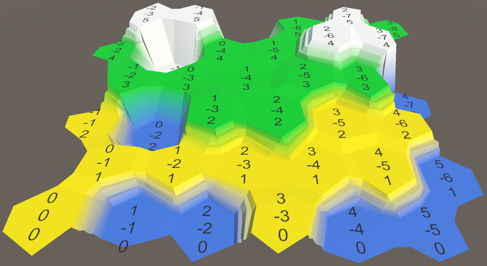
Consistent use of cell heights.
unitypackage
Cell Edge Division
Although cells have beautiful variability, they still look like obvious hexagons. This in itself is not a problem, but we can improve their appearance.
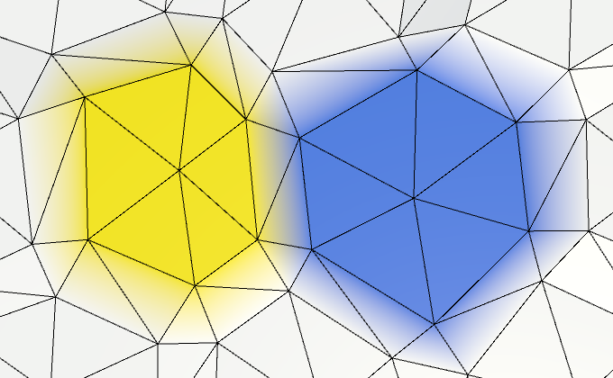
Clearly visible hexagonal cells.
If we had more vertices, then there would be more local variation. So let's split each edge of a cell into two parts, adding the top of the edge in the middle between each pair of corners. This means that
HexMesh.Triangulate should add not one, but two triangles. void Triangulate (HexDirection direction, HexCell cell) { Vector3 center = cell.Position; Vector3 v1 = center + HexMetrics.GetFirstSolidCorner(direction); Vector3 v2 = center + HexMetrics.GetSecondSolidCorner(direction); Vector3 e1 = Vector3.Lerp(v1, v2, 0.5f); AddTriangle(center, v1, e1); AddTriangleColor(cell.color); AddTriangle(center, e1, v2); AddTriangleColor(cell.color); if (direction <= HexDirection.SE) { TriangulateConnection(direction, cell, v1, v2); } } 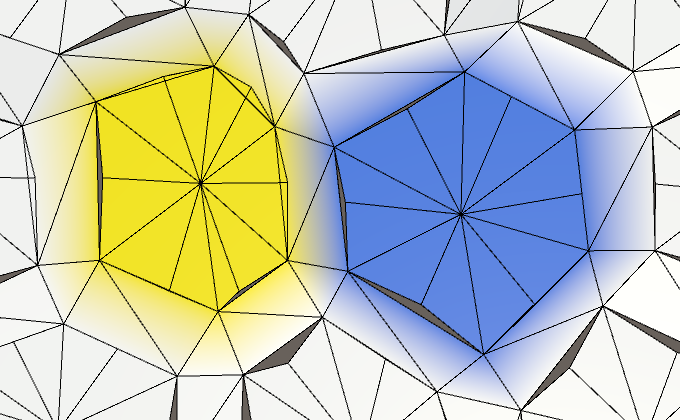
Twelve sides instead of six.
Doubling vertices and triangles adds more variation to the edges of the cell. Let's make them even more irregular by tripling the number of vertices.
Vector3 e1 = Vector3.Lerp(v1, v2, 1f / 3f); Vector3 e2 = Vector3.Lerp(v1, v2, 2f / 3f); AddTriangle(center, v1, e1); AddTriangleColor(cell.color); AddTriangle(center, e1, e2); AddTriangleColor(cell.color); AddTriangle(center, e2, v2); AddTriangleColor(cell.color); 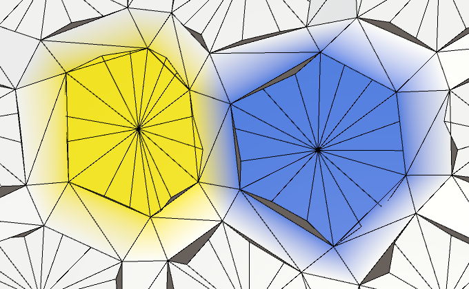
18 sides.
Rib connection division
Of course, we also need to subdivide rib connections. Therefore, we pass the new vertex edges to the
TriangulateConnection . if (direction <= HexDirection.SE) { TriangulateConnection(direction, cell, v1, e1, e2, v2); } Add the appropriate parameters to
TriangulateConnection so that it can work with additional vertices. void TriangulateConnection ( HexDirection direction, HexCell cell, Vector3 v1, Vector3 e1, Vector3 e2, Vector3 v2 ) { … } We also need to compute the additional vertices of the edges for neighboring cells. We can calculate them after connecting the bridge to the other side.
Vector3 bridge = HexMetrics.GetBridge(direction); Vector3 v3 = v1 + bridge; Vector3 v4 = v2 + bridge; v3.y = v4.y = neighbor.Position.y; Vector3 e3 = Vector3.Lerp(v3, v4, 1f / 3f); Vector3 e4 = Vector3.Lerp(v3, v4, 2f / 3f); Next, we need to change the edge triangulation. While we ignore the slopes with ledges, we simply add three instead of one quad.
if (cell.GetEdgeType(direction) == HexEdgeType.Slope) { TriangulateEdgeTerraces(v1, v2, cell, v3, v4, neighbor); } else { AddQuad(v1, e1, v3, e3); AddQuadColor(cell.color, neighbor.color); AddQuad(e1, e2, e3, e4); AddQuadColor(cell.color, neighbor.color); AddQuad(e2, v2, e4, v4); AddQuadColor(cell.color, neighbor.color); } 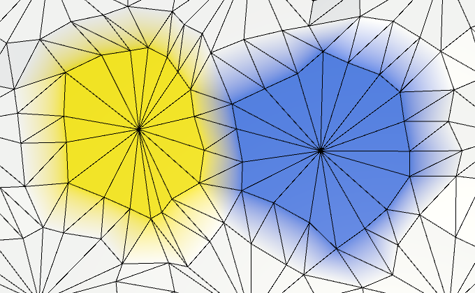
Subdivided connections.
Edge vertex union
Since we now need four vertices to describe the edge, it would be logical to combine them into a set. This is more convenient than working with four independent vertices. Create a simple structure for this
EdgeVertices . It should contain four vertices, going in clockwise order along the edge of the cell. using UnityEngine; public struct EdgeVertices { public Vector3 v1, v2, v3, v4; } Shouldn't they be serializable?
We will use this structure only during triangulation. At this stage, we do not need to store the vertex edges, so it is not necessary to do them serialized.
Add a convenient constructor method to it, which will calculate the intermediate points of the edge.
public EdgeVertices (Vector3 corner1, Vector3 corner2) { v1 = corner1; v2 = Vector3.Lerp(corner1, corner2, 1f / 3f); v3 = Vector3.Lerp(corner1, corner2, 2f / 3f); v4 = corner2; } Now we can add a separate triangulation method to
HexMesh to create a fan of triangles between the center of the cell and one of its edges. void TriangulateEdgeFan (Vector3 center, EdgeVertices edge, Color color) { AddTriangle(center, edge.v1, edge.v2); AddTriangleColor(color); AddTriangle(center, edge.v2, edge.v3); AddTriangleColor(color); AddTriangle(center, edge.v3, edge.v4); AddTriangleColor(color); } And a method for triangulating a strip of quadrilaterals between two edges.
void TriangulateEdgeStrip ( EdgeVertices e1, Color c1, EdgeVertices e2, Color c2 ) { AddQuad(e1.v1, e1.v2, e2.v1, e2.v2); AddQuadColor(c1, c2); AddQuad(e1.v2, e1.v3, e2.v2, e2.v3); AddQuadColor(c1, c2); AddQuad(e1.v3, e1.v4, e2.v3, e2.v4); AddQuadColor(c1, c2); } This will allow us to simplify the
Triangulate method. void Triangulate (HexDirection direction, HexCell cell) { Vector3 center = cell.Position; EdgeVertices e = new EdgeVertices( center + HexMetrics.GetFirstSolidCorner(direction), center + HexMetrics.GetSecondSolidCorner(direction) ); TriangulateEdgeFan(center, e, cell.color); if (direction <= HexDirection.SE) { TriangulateConnection(direction, cell, e); } } Let's go to
TriangulateConnection . Now we can use TriangulateEdgeStrip , but other changes need to be made. Where we used v1 before, we need to use e1.v1 . Similarly, v2 becomes e1.v4 , v3 becomes e2.v1 , and v4 becomes e2.v4 . void TriangulateConnection ( HexDirection direction, HexCell cell, EdgeVertices e1 ) { HexCell neighbor = cell.GetNeighbor(direction); if (neighbor == null) { return; } Vector3 bridge = HexMetrics.GetBridge(direction); bridge.y = neighbor.Position.y - cell.Position.y; EdgeVertices e2 = new EdgeVertices( e1.v1 + bridge, e1.v4 + bridge ); if (cell.GetEdgeType(direction) == HexEdgeType.Slope) { TriangulateEdgeTerraces(e1.v1, e1.v4, cell, e2.v1, e2.v4, neighbor); } else { TriangulateEdgeStrip(e1, cell.color, e2, neighbor.color); } HexCell nextNeighbor = cell.GetNeighbor(direction.Next()); if (direction <= HexDirection.E && nextNeighbor != null) { Vector3 v5 = e1.v4 + HexMetrics.GetBridge(direction.Next()); v5.y = nextNeighbor.Position.y; if (cell.Elevation <= neighbor.Elevation) { if (cell.Elevation <= nextNeighbor.Elevation) { TriangulateCorner( e1.v4, cell, e2.v4, neighbor, v5, nextNeighbor ); } else { TriangulateCorner( v5, nextNeighbor, e1.v4, cell, e2.v4, neighbor ); } } else if (neighbor.Elevation <= nextNeighbor.Elevation) { TriangulateCorner( e2.v4, neighbor, v5, nextNeighbor, e1.v4, cell ); } else { TriangulateCorner( v5, nextNeighbor, e1.v4, cell, e2.v4, neighbor ); } } Ledge division
We need to subdivide and ledges. Therefore, we pass the edges to
TriangulateEdgeTerraces . if (cell.GetEdgeType(direction) == HexEdgeType.Slope) { TriangulateEdgeTerraces(e1, cell, e2, neighbor); } Now we need to change the
TriangulateEdgeTerraces so that it interpolates between edges, and not between pairs of vertices. Let's assume that EdgeVertices has a convenient static method for this. This will allow us to simplify TriangulateEdgeTerraces , rather than complicate it. void TriangulateEdgeTerraces ( EdgeVertices begin, HexCell beginCell, EdgeVertices end, HexCell endCell ) { EdgeVertices e2 = EdgeVertices.TerraceLerp(begin, end, 1); Color c2 = HexMetrics.TerraceLerp(beginCell.color, endCell.color, 1); TriangulateEdgeStrip(begin, beginCell.color, e2, c2); for (int i = 2; i < HexMetrics.terraceSteps; i++) { EdgeVertices e1 = e2; Color c1 = c2; e2 = EdgeVertices.TerraceLerp(begin, end, i); c2 = HexMetrics.TerraceLerp(beginCell.color, endCell.color, i); TriangulateEdgeStrip(e1, c1, e2, c2); } TriangulateEdgeStrip(e2, c2, end, endCell.color); } The
EdgeVertices.TerraceLerp method simply interpolates the ledges between all four pairs of vertices of two edges. public static EdgeVertices TerraceLerp ( EdgeVertices a, EdgeVertices b, int step) { EdgeVertices result; result.v1 = HexMetrics.TerraceLerp(a.v1, b.v1, step); result.v2 = HexMetrics.TerraceLerp(a.v2, b.v2, step); result.v3 = HexMetrics.TerraceLerp(a.v3, b.v3, step); result.v4 = HexMetrics.TerraceLerp(a.v4, b.v4, step); return result; } 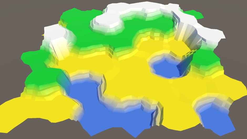
Subdivided ledges.
unitypackage
Reconnect the cliffs and ledges
While we ignored the cracks in the joints of cliffs and ledges. It is time to solve this problem. Let's first consider the cases of "precipice-slope-slope" (OSS) and "slope-precipice-slope" (SOS).
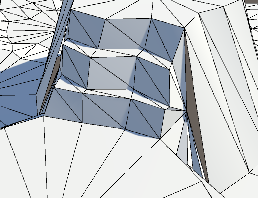
Holes in meshe.
The problem arises because the vertices of the borders have moved. This means that now they do not lie flat on the side of the cliff, which leads to a crack. Sometimes these holes are invisible, and sometimes striking.
The solution is to not move the top of the border. This means that we need to control whether the point will be moved. The easiest way is to create an alternative to
AddTriangle , which does not move vertices at all. void AddTriangleUnperturbed (Vector3 v1, Vector3 v2, Vector3 v3) { int vertexIndex = vertices.Count; vertices.Add(v1); vertices.Add(v2); vertices.Add(v3); triangles.Add(vertexIndex); triangles.Add(vertexIndex + 1); triangles.Add(vertexIndex + 2); } Change the
TriangulateBoundaryTriangle so that it uses this method. This means that it will have to explicitly move all the vertices, except for the boundary ones. void TriangulateBoundaryTriangle ( Vector3 begin, HexCell beginCell, Vector3 left, HexCell leftCell, Vector3 boundary, Color boundaryColor ) { Vector3 v2 = HexMetrics.TerraceLerp(begin, left, 1); Color c2 = HexMetrics.TerraceLerp(beginCell.color, leftCell.color, 1); AddTriangleUnperturbed(Perturb(begin), Perturb(v2), boundary); AddTriangleColor(beginCell.color, c2, boundaryColor); for (int i = 2; i < HexMetrics.terraceSteps; i++) { Vector3 v1 = v2; Color c1 = c2; v2 = HexMetrics.TerraceLerp(begin, left, i); c2 = HexMetrics.TerraceLerp(beginCell.color, leftCell.color, i); AddTriangleUnperturbed(Perturb(v1), Perturb(v2), boundary); AddTriangleColor(c1, c2, boundaryColor); } AddTriangleUnperturbed(Perturb(v2), Perturb(left), boundary); AddTriangleColor(c2, leftCell.color, boundaryColor); } It is worth noting the following: since we do not use
v2 to get some other point, we can move it immediately. This is a simple optimization and it reduces the amount of code, so let's add it. void TriangulateBoundaryTriangle ( Vector3 begin, HexCell beginCell, Vector3 left, HexCell leftCell, Vector3 boundary, Color boundaryColor ) { Vector3 v2 = Perturb(HexMetrics.TerraceLerp(begin, left, 1)); Color c2 = HexMetrics.TerraceLerp(beginCell.color, leftCell.color, 1); AddTriangleUnperturbed(Perturb(begin), v2, boundary); AddTriangleColor(beginCell.color, c2, boundaryColor); for (int i = 2; i < HexMetrics.terraceSteps; i++) { Vector3 v1 = v2; Color c1 = c2; v2 = Perturb(HexMetrics.TerraceLerp(begin, left, i)); c2 = HexMetrics.TerraceLerp(beginCell.color, leftCell.color, i); AddTriangleUnperturbed(v1, v2, boundary); AddTriangleColor(c1, c2, boundaryColor); } AddTriangleUnperturbed(v2, Perturb(left), boundary); AddTriangleColor(c2, leftCell.color, boundaryColor); } 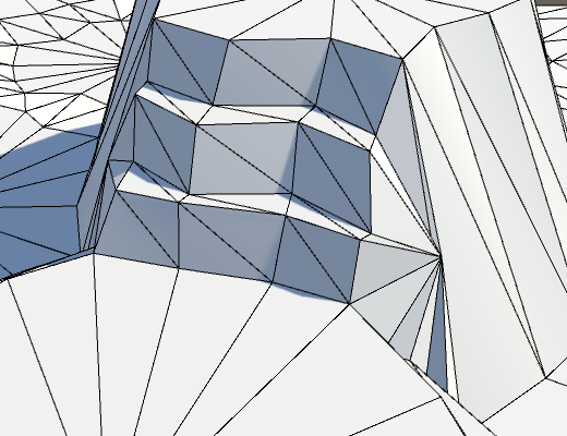
Unmoved boundaries.
It looks better, but we have not finished yet. Inside the
TriangulateCornerTerracesCliff method, the boundary point is interpolated between the left and right points. However, these points have not yet been moved. In order for the boundary point to match the resulting break, we need to perform an interpolation between the displaced points. Vector3 boundary = Vector3.Lerp(Perturb(begin), Perturb(right), b); The same is true for the
TriangulateCornerCliffTerraces method. Vector3 boundary = Vector3.Lerp(Perturb(begin), Perturb(left), b); 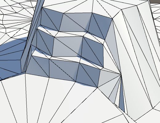
Holes are gone.
Double cliffs and slope
In all the remaining problem cases, there are two cliffs and one slope.

A big hole because of a single triangle.
This issue is resolved by manually moving a single triangle in the
else block at the end of TriangulateCornerTerracesCliff . else { AddTriangleUnperturbed(Perturb(left), Perturb(right), boundary); AddTriangleColor(leftCell.color, rightCell.color, boundaryColor); } The same applies to
TriangulateCornerCliffTerraces . else { AddTriangleUnperturbed(Perturb(left), Perturb(right), boundary); AddTriangleColor(leftCell.color, rightCell.color, boundaryColor); } 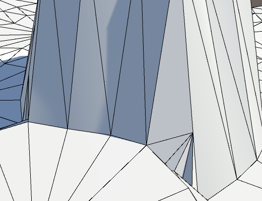
Get rid of the last cracks.
unitypackage
Revision
Now we have a completely correct distorted mesh. Its appearance depends on the specific noise, its scale and the forces of distortion. In our case, the distortion may seem too strong. Although this irregularity looks beautiful, we do not want the cells to deviate too far from a flat grid. In the end, we still use it to define a variable cell. And if the cell size will vary too much, then it will be more difficult for us to place the content in them.
Undistorted and distorted mesh.
It seems that the power of 5 to distort the cells is too great.
Cell distortion from 0 to 5.
Let's reduce it to 4 in order to increase the convenience of the grid without making it too correct. This ensures that the maximum offset in XZ will be √32 ≈ 5.66 units.
public const float cellPerturbStrength = 4f; 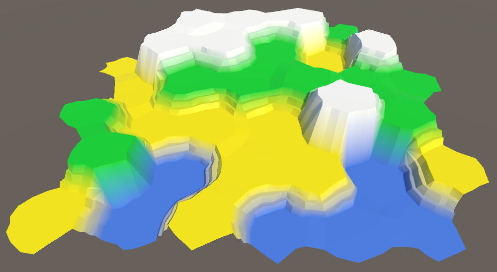
Cell distortion force 4.
Another value that can be changed is the coefficient of wholeness. If we increase it, the flat centers of the cells will become larger, that is, there will be more room for future content. Of course, with this they will become more hexagonal.
Integrity factor from 0.75 to 0.95.
A small increase in the coefficient of integrity up to 0.8 will slightly simplify our life in the future.
public const float solidFactor = 0.8f; 
Integrity coefficient 0.8.
Finally, you can see that the differences between the levels of heights are too sharp. This is useful when you need to make sure that the mesh is correctly generated, but we are already done with it. Let's reduce it to 1 unit per step of the ledge, that is, to 3.
public const float elevationStep = 3f; 
The pitch is reduced to 3.
Also we can change the height distortion force. But now it has a value of 1.5, which is equal to half the height step, which suits us.
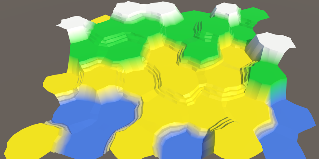
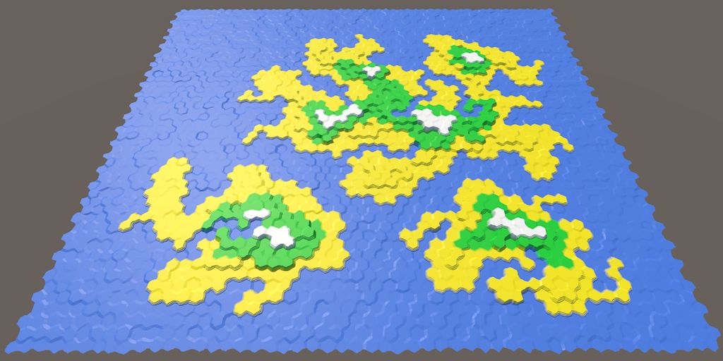
Small steps of heights make it more logical to use all seven levels of height. This increases the variability of the map.
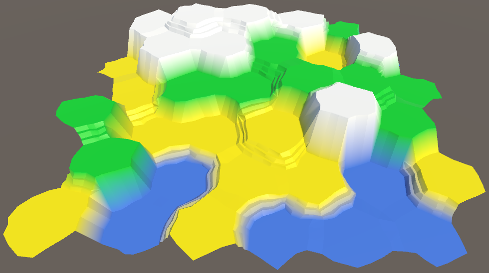
Use seven levels of heights.
unitypackage
Part 5: Larger Cards
- Divide the grid into fragments.
- We control the camera.
- We color the colors and heights separately.
- Use the enlarged brush cells.
So far we have been working with a very small map. It is time to increase it.
It's time to zoom.
Grid Fragments
We cannot make the grid too large, because we will rest on the limits of what can fit in one mesh. How to solve this problem?Use multiple meshes. For this we need to divide our grid into several fragments. We use rectangular fragments of constant size.
Breaking the grid into 3 by 3 segments.
Let's use blocks 5 by 5, that is, 25 cells per fragment. We define them in
HexMetrics. public const int chunkSizeX = 5, chunkSizeZ = 5; What fragment size can be considered appropriate?
It is hard to say. , . . , (frustum culling), . .
Now we can not use any size for the grid, it must be a multiple of the fragment size. Therefore, let's change it
HexGridso that it sets its size not in separate cells, but in fragments. Set the default size to 4 for 3 fragments, that is, a total of 12 fragments or 300 cells. So we get a convenient test card. public int chunkCountX = 4, chunkCountZ = 3; We still use
widthand height, but now they have to become private. And rename them to cellCountXand cellCountZ. Use the editor to rename all occurrences of these variables at once. Now it will be clear when we are dealing with the number of fragments or cells. // public int width = 6; // public int height = 6; int cellCountX, cellCountZ; 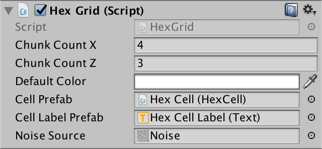
Specify the size in fragments.
Let's change
Awakeso that if necessary from the number of fragments the number of cells was calculated. Select the creation of cells in a separate method, so as not to litter Awake. void Awake () { HexMetrics.noiseSource = noiseSource; gridCanvas = GetComponentInChildren<Canvas>(); hexMesh = GetComponentInChildren<HexMesh>(); cellCountX = chunkCountX * HexMetrics.chunkSizeX; cellCountZ = chunkCountZ * HexMetrics.chunkSizeZ; CreateCells(); } void CreateCells () { cells = new HexCell[cellCountZ * cellCountX]; for (int z = 0, i = 0; z < cellCountZ; z++) { for (int x = 0; x < cellCountX; x++) { CreateCell(x, z, i++); } } } Fragment prefab
To describe the mesh fragments, we need a new type of components.
using UnityEngine; using UnityEngine.UI; public class HexGridChunk : MonoBehaviour { } Next we will create a prefab fragment. We do this by duplicating a Hex Grid object and renaming it to Hex Grid Chunk . Remove its component
HexGridand add a component instead HexGridChunk. Then turn it into a prefab and remove the object from the scene.

Prefab fragment with its own canvas and mesh.
Since the copies of these fragments will be created
HexGrid, we will give him a link to the fragment prefab. public HexGridChunk chunkPrefab; 
Now with the fragments.
Creating instances of fragments is a lot like creating instances of cells. We will track them using an array, and to fill it we will use a double loop.
HexGridChunk[] chunks; void Awake () { … CreateChunks(); CreateCells(); } void CreateChunks () { chunks = new HexGridChunk[chunkCountX * chunkCountZ]; for (int z = 0, i = 0; z < chunkCountZ; z++) { for (int x = 0; x < chunkCountX; x++) { HexGridChunk chunk = chunks[i++] = Instantiate(chunkPrefab); chunk.transform.SetParent(transform); } } } The initialization of the fragment is similar to how we initialized the grid of hexagons. It sets everything in
Awakeand performs triangulation in Start. It requires a reference to its canvas and mesh, as well as an array for the cells. However, the fragment will not create these cells. This will still be done by the grid. public class HexGridChunk : MonoBehaviour { HexCell[] cells; HexMesh hexMesh; Canvas gridCanvas; void Awake () { gridCanvas = GetComponentInChildren<Canvas>(); hexMesh = GetComponentInChildren<HexMesh>(); cells = new HexCell[HexMetrics.chunkSizeX * HexMetrics.chunkSizeZ]; } void Start () { hexMesh.Triangulate(cells); } } Assigning cells to fragments
HexGridstill creates all the cells. This is normal, but now we need to add each cell to the appropriate fragment, and not specify them using our own mesh and canvas. void CreateCell (int x, int z, int i) { … HexCell cell = cells[i] = Instantiate<HexCell>(cellPrefab); // cell.transform.SetParent(transform, false); cell.transform.localPosition = position; cell.coordinates = HexCoordinates.FromOffsetCoordinates(x, z); cell.color = defaultColor; … Text label = Instantiate<Text>(cellLabelPrefab); // label.rectTransform.SetParent(gridCanvas.transform, false); label.rectTransform.anchoredPosition = new Vector2(position.x, position.z); label.text = cell.coordinates.ToStringOnSeparateLines(); cell.uiRect = label.rectTransform; cell.Elevation = 0; AddCellToChunk(x, z, cell); } void AddCellToChunk (int x, int z, HexCell cell) { } We can find the correct fragment using integer division
xand zthe size of the fragment. void AddCellToChunk (int x, int z, HexCell cell) { int chunkX = x / HexMetrics.chunkSizeX; int chunkZ = z / HexMetrics.chunkSizeZ; HexGridChunk chunk = chunks[chunkX + chunkZ * chunkCountX]; } Using intermediate results, we can also determine the local cell index in this fragment. After that you can add a cell to the fragment.
void AddCellToChunk (int x, int z, HexCell cell) { int chunkX = x / HexMetrics.chunkSizeX; int chunkZ = z / HexMetrics.chunkSizeZ; HexGridChunk chunk = chunks[chunkX + chunkZ * chunkCountX]; int localX = x - chunkX * HexMetrics.chunkSizeX; int localZ = z - chunkZ * HexMetrics.chunkSizeZ; chunk.AddCell(localX + localZ * HexMetrics.chunkSizeX, cell); } Then it
HexGridChunk.AddCellputs the cell in its own array, and then it sets the parent elements for the cell and its UI. public void AddCell (int index, HexCell cell) { cells[index] = cell; cell.transform.SetParent(transform, false); cell.uiRect.SetParent(gridCanvas.transform, false); } Cleaning up
At this stage, it
HexGridcan get rid of its child elements of the canvas and the mesh of hexagons, as well as the code. // Canvas gridCanvas; // HexMesh hexMesh; void Awake () { HexMetrics.noiseSource = noiseSource; // gridCanvas = GetComponentInChildren<Canvas>(); // hexMesh = GetComponentInChildren<HexMesh>(); … } // void Start () { // hexMesh.Triangulate(cells); // } // public void Refresh () { // hexMesh.Triangulate(cells); // } Since we got rid of
Refresh, then should HexMapEditorno longer use it. void EditCell (HexCell cell) { cell.color = activeColor; cell.Elevation = activeElevation; // hexGrid.Refresh(); } 
Cleared hexagon grid.
After starting the Play mode, the map still looks the same. But the hierarchy of objects will be different. Hex Grid now creates child objects of fragments that contain cells, as well as their mesh and canvas.

Child fragments in Play mode.
Perhaps we have some problems with the labels of the cells. Initially, we set the width of the label 5. This was enough to display two characters, which we had enough on a small map. But now we can have coordinates such as −10, in which there are three characters. They will not fit and will be trimmed. To fix this, increase the width of the cell label to 10, or even more.


Extended Cell Labels.
Now we can create much larger cards! Since we generate the entire grid at launch, it may take a long time to create large maps. But after completion we will have a huge space for experiments.
Correct cell editing
At the current stage, editing does not seem to work, because we are no longer updating the grid. We need to update individual fragments, so we add a method
Refreshto HexGridChunk. public void Refresh () { hexMesh.Triangulate(cells); } When do we call this method? We updated the whole mesh every time, because we only had one mesh. But now we have a lot of fragments. Instead of updating all of them every time, it will be much more efficient to update the changed fragments. Otherwise, changing large cards will become a very brake operation.
But how do you know which fragment we update? The easiest way is to make each cell know which fragment it belongs to. Then the cell will be able to update its fragment when this cell changes. So let's give a
HexCelllink to its fragment. public HexGridChunk chunk; HexGridChunk may, when added, assign itself to the cell. public void AddCell (int index, HexCell cell) { cells[index] = cell; cell.chunk = this; cell.transform.SetParent(transform, false); cell.uiRect.SetParent(gridCanvas.transform, false); } Combining them, we add to the
HexCellmethod Refresh. Each time a cell is updated, it will simply update its fragment. void Refresh () { chunk.Refresh(); } We don’t have to be
HexCell.Refreshshared, because the cell itself knows better when it was changed. For example, after its height has been changed. public int Elevation { get { return elevation; } set { … Refresh(); } } In fact, we need to update it only when its height has changed to another value. She doesn't even need to re-calculate anything if we assign her the same height as before. Therefore, we can get out of the beginning of the setter.
public int Elevation { get { return elevation; } set { if (elevation == value) { return; } … } } However, we will also skip the calculations for the first time when the height is set to 0, because this is the default value of the grid height. To avoid this, let us make sure that the initial value is such that we never use.
int elevation = int.MinValue; What is int.MinValue?
, integer. C# integer —
32- , 2 32 integer, , . .
— −2 31 = −2 147 483 648. !
2 31 − 1 = 2 147 483 647. 2 31 - .
32- , 2 32 integer, , . .
— −2 31 = −2 147 483 648. !
2 31 − 1 = 2 147 483 647. 2 31 - .
To recognize the color change of a cell, we also need to turn it into a property. Rename it
Colorwith a capital letter, and then turn it into a property with a private variable color. The default color value is transparent black, which suits us. public Color Color { get { return color; } set { if (color == value) { return; } color = value; Refresh(); } } Color color; Now when we start Play mode, we get null-reference exceptions. This is because we assigned default values to color and height before assigning the cell to its fragment. It is normal that at this stage we do not update the fragments, because we triangulate them after the completion of the entire initialization. In other words, we update the fragment only if it is assigned.
void Refresh () { if (chunk) { chunk.Refresh(); } } We can finally change the cells again! However, a problem arises. When drawing along the edges of the fragments appear seams.

Errors on the boundaries of the fragments.
This is logical, because when a single cell changes, all connections with its neighbors also change. And these neighbors may be in other fragments. The simplest solution is to update all neighboring cells, if they are different.
void Refresh () { if (chunk) { chunk.Refresh(); for (int i = 0; i < neighbors.Length; i++) { HexCell neighbor = neighbors[i]; if (neighbor != null && neighbor.chunk != chunk) { neighbor.chunk.Refresh(); } } } } Although this works, it may turn out that we update one fragment several times. And when we start painting a few cells at a time, everything will get worse.
But we are not obliged to immediately triangulate after updating the fragment. Instead, we simply write down what needs to be updated, and triangulate after the change is complete.
Since
HexGridChunknothing else does, we can use its enabled state to signal the need for an update. When updating it, we enable the component. Turning it on several times will not change anything. Later, the component is updated. We will perform triangulation at this stage and disable the component again.We use
LateUpdateinsteadUpdate to ensure that triangulation occurs after the completion of a change for the current frame. public void Refresh () { // hexMesh.Triangulate(cells); enabled = true; } void LateUpdate () { hexMesh.Triangulate(cells); enabled = false; } What is the difference between Update and LateUpdate?
Update - . LateUpdate . , .Since our component is enabled by default by default, we no longer need to explicitly triangulate to
Start. Therefore, this method can be removed. // void Start () { // hexMesh.Triangulate(cells); // } 
Fragments 20 by 20 containing 10,000 cells.
Generalized lists
Although we have significantly changed the way the grid is triangulated, it
HexMeshstill remains the same. All he needs to work is an array of cells. He does not care whether one mesh of hexagons, or several. But we have not yet considered the use of several meshes. Perhaps something can be improved here?Used
HexMeshlists are essentially temporary buffers. They are used only with triangulation. And the fragments are triangulated one at a time. Therefore, in reality, we need only one set of lists, and not one set for each object of the mesh of hexagons. This can be achieved by making the lists static. static List<Vector3> vertices = new List<Vector3>(); static List<Color> colors = new List<Color>(); static List<int> triangles = new List<int>(); void Awake () { GetComponent<MeshFilter>().mesh = hexMesh = new Mesh(); meshCollider = gameObject.AddComponent<MeshCollider>(); hexMesh.name = "Hex Mesh"; // vertices = new List<Vector3>(); // colors = new List<Color>(); // triangles = new List<int>(); } Are static lists really that important?
. , , .
, . 20 20 100.
, . 20 20 100.
unitypackage
Camera control
A big camera is great, but it is useless if we cannot see it. To view the entire map, we need to move the camera. Also useful zoom. So let's create a camera that allows you to perform these actions.
Create a dummy object and name it Hex Map Camera . Drop its transform component so that it moves to the origin without changing its rotation and scale. Add a child object called Swivel to it , and add a child Stick object to it . Let's make the main camera a child element of the Stick, and reset its transform component.

The hierarchy of the camera.
The task of the camera hinge (Swivel) is to control the angle at which the camera looks at the map. Let him turn (45, 0, 0). The stick controls the distance at which the cameras are located. We assign it a position (0, 0, -45).
Now we need a component to manage this system. Assign this component to the root of the camera hierarchy. Give him a link to the hinge and handle, getting them in
Awake. using UnityEngine; public class HexMapCamera : MonoBehaviour { Transform swivel, stick; void Awake () { swivel = transform.GetChild(0); stick = swivel.GetChild(0); } } 
Camera cards of hexagons.
Zoom
The first function we create is zooming (zoom). We can control the current zoom level with the variable float. A value of 0 means that we are completely distant, and a value of 1 means that we are completely close. Let's start with the maximum zoom.
float zoom = 1f; Zoom will usually be performed by mouse wheel or analog control. We can implement it using the default Mouse ScrollWheel input axis . Add a method
Updatethat checks for the presence of an input delta, and if there is one, it calls the method for changing the zoom. void Update () { float zoomDelta = Input.GetAxis("Mouse ScrollWheel"); if (zoomDelta != 0f) { AdjustZoom(zoomDelta); } } void AdjustZoom (float delta) { } To change the zoom level, we will simply add a delta to it, and then limit the value (clamp) to remain in the range of 0–1.
void AdjustZoom (float delta) { zoom = Mathf.Clamp01(zoom + delta); } When you zoom in and zoom out, the distance to the camera should change accordingly. This can be done by changing the position of the knob in Z. We add two common float variables to adjust the position of the knob with the minimum and maximum zoom. Since we are developing a relatively small map, let's set the values to -250 and -45.
public float stickMinZoom, stickMaxZoom; After changing the zoom, we perform linear interpolation between these two values based on the new zoom value. Then update the pen position.
void AdjustZoom (float delta) { zoom = Mathf.Clamp01(zoom + delta); float distance = Mathf.Lerp(stickMinZoom, stickMaxZoom, zoom); stick.localPosition = new Vector3(0f, 0f, distance); } 
The minimum and maximum value of the stick.
Now the zoom works, but so far it is not very useful. Usually at a distance of the zoom, the camera goes into top view We can do this by turning the hinge. Therefore, we add the variables min and max for the hinge. Give them the values of 90 and 45.
public float swivelMinZoom, swivelMaxZoom; As in the case with the handle position, we interpolate to find a suitable zoom angle. Then we set the rotation of the hinge.
void AdjustZoom (float delta) { zoom = Mathf.Clamp01(zoom + delta); float distance = Mathf.Lerp(stickMinZoom, stickMaxZoom, zoom); stick.localPosition = new Vector3(0f, 0f, distance); float angle = Mathf.Lerp(swivelMinZoom, swivelMaxZoom, zoom); swivel.localRotation = Quaternion.Euler(angle, 0f, 0f); } 
The minimum and maximum Swivel values.
The rate of change of the zoom can be adjusted by changing the sensitivity of the input parameters of the mouse wheel. They can be found in Edit / Project Settings / Input . For example, changing them from 0.1 to 0.025, we get a slower and smoother zoom.

Mouse wheel input options.
Move
Now let's move on to moving the camera. The movement in the direction of X and Z we must implement in
Update, as is the case with the zoom. We can use for this input axis Horizontal and Vertical . This will allow us to move the camera with the arrows and WASD keys. void Update () { float zoomDelta = Input.GetAxis("Mouse ScrollWheel"); if (zoomDelta != 0f) { AdjustZoom(zoomDelta); } float xDelta = Input.GetAxis("Horizontal"); float zDelta = Input.GetAxis("Vertical"); if (xDelta != 0f || zDelta != 0f) { AdjustPosition(xDelta, zDelta); } } void AdjustPosition (float xDelta, float zDelta) { } The simplest approach is to get the current position of the camera system, add the deltas X and Z to it, and assign the result to the system position.
void AdjustPosition (float xDelta, float zDelta) { Vector3 position = transform.localPosition; position += new Vector3(xDelta, 0f, zDelta); transform.localPosition = position; } Due to this, the camera will move while holding the arrows or WASD, but not at a constant speed. It will depend on the frame rate. To determine the distance to move, we use the time delta, as well as the desired speed of movement. Therefore, we add a common variable
moveSpeedand set it to 100, and then multiply it by the time delta to get the delta position. public float moveSpeed; void AdjustPosition (float xDelta, float zDelta) { float distance = moveSpeed * Time.deltaTime; Vector3 position = transform.localPosition; position += new Vector3(xDelta, 0f, zDelta) * distance; transform.localPosition = position; } 
Moving speed
Now we can move at a constant speed along the X or Z axes. But when moving along both axes at the same time (diagonally), the movement will be faster. To fix this, we need to normalize the delta vector. This will use it as a referral.
void AdjustPosition (float xDelta, float zDelta) { Vector3 direction = new Vector3(xDelta, 0f, zDelta).normalized; float distance = moveSpeed * Time.deltaTime; Vector3 position = transform.localPosition; position += direction * distance; transform.localPosition = position; } The diagonal movement is now implemented correctly, but suddenly it turns out that the camera continues to move for quite a long time even after all the keys are released. This happens because the input axes do not instantly jump to the limit values immediately after pressing the keys. They need some time for this. The same is true for releasing keys. It takes time to return to zero axis values. However, since we normalized the input values, the maximum speed is kept constant.
We can adjust the input parameters to get rid of delays, but they give a feeling of smoothness that is worth saving. We can apply the most extreme value of the axes as the attenuation coefficient of the motion.
Vector3 direction = new Vector3(xDelta, 0f, zDelta).normalized; float damping = Mathf.Max(Mathf.Abs(xDelta), Mathf.Abs(zDelta)); float distance = moveSpeed * damping * Time.deltaTime; Motion with damping.
Now the movement works well, at least with the zoom. But at a distance it turns out to be too slow. With a reduced zoom, we need to speed up. This can be done by replacing one variable
moveSpeedwith two for the minimum and maximum zoom, and then performing the interpolation. Assign them the values 400 and 100. // public float moveSpeed; public float moveSpeedMinZoom, moveSpeedMaxZoom; void AdjustPosition (float xDelta, float zDelta) { Vector3 direction = new Vector3(xDelta, 0f, zDelta).normalized; float damping = Mathf.Max(Mathf.Abs(xDelta), Mathf.Abs(zDelta)); float distance = Mathf.Lerp(moveSpeedMinZoom, moveSpeedMaxZoom, zoom) * damping * Time.deltaTime; Vector3 position = transform.localPosition; position += direction * distance; transform.localPosition = position; } 
Movement speed varies with zoom level.
Now we can quickly navigate the map! In fact, we can move far beyond the map, but this is undesirable. The camera must remain inside the card. To ensure this, we need to know the boundaries of the map, so we need a reference to the grid. Add and connect it.
public HexGrid grid; 
You need to request the size of the grid.
After moving to a new position, we will limit it with the help of a new method.
void AdjustPosition (float xDelta, float zDelta) { … transform.localPosition = ClampPosition(position); } Vector3 ClampPosition (Vector3 position) { return position; } Position X has a minimum value of 0, and the maximum is determined by the size of the map.
Vector3 ClampPosition (Vector3 position) { float xMax = grid.chunkCountX * HexMetrics.chunkSizeX * (2f * HexMetrics.innerRadius); position.x = Mathf.Clamp(position.x, 0f, xMax); return position; } The same applies to position Z.
Vector3 ClampPosition (Vector3 position) { float xMax = grid.chunkCountX * HexMetrics.chunkSizeX * (2f * HexMetrics.innerRadius); position.x = Mathf.Clamp(position.x, 0f, xMax); float zMax = grid.chunkCountZ * HexMetrics.chunkSizeZ * (1.5f * HexMetrics.outerRadius); position.z = Mathf.Clamp(position.z, 0f, zMax); return position; } In fact, this is a bit inaccurate. The origin is in the center of the cell, not on the left. Therefore, we want the camera to stop at the center of the rightmost cells. To do this, subtract half the cell from the maximum X.
float xMax = (grid.chunkCountX * HexMetrics.chunkSizeX - 0.5f) * (2f * HexMetrics.innerRadius); position.x = Mathf.Clamp(position.x, 0f, xMax); For the same reason, you need to reduce the maximum of Z. Since the metrics are slightly different, we need to subtract the full cell.
float zMax = (grid.chunkCountZ * HexMetrics.chunkSizeZ - 1) * (1.5f * HexMetrics.outerRadius); position.z = Mathf.Clamp(position.z, 0f, zMax); With the movement we finished, only a small detail remained. Sometimes the UI responds to the arrow keys, and this causes the slider to move as the camera moves. This happens when the UI considers itself active after you have clicked on it and the cursor continues to be above it.
You can disable UI from listening to keyboard input. This can be done by ordering the EventSystem object not to execute Send Navigation Events .

No more navigation events.
Turn
Want to see what is behind the cliff? It would be convenient to be able to rotate the camera! Let's add this feature.
The zoom level is not important for rotation, only speed is enough. Add a common variable
rotationSpeedand set it to a value of 180 degrees. Check the turn delta in Update, sampling the Rotation axis and changing the turn if necessary. public float rotationSpeed; void Update () { float zoomDelta = Input.GetAxis("Mouse ScrollWheel"); if (zoomDelta != 0f) { AdjustZoom(zoomDelta); } float rotationDelta = Input.GetAxis("Rotation"); if (rotationDelta != 0f) { AdjustRotation(rotationDelta); } float xDelta = Input.GetAxis("Horizontal"); float zDelta = Input.GetAxis("Vertical"); if (xDelta != 0f || zDelta != 0f) { AdjustPosition(xDelta, zDelta); } } void AdjustRotation (float delta) { } 
Turning speed.
In fact, there is no default Rotation axis . We have to create it ourselves. Let's go over the input parameters and duplicate the topmost Vertical entry . Change the duplicate name to Rotation and change the keys to QE and a comma (,) with a period (.).

The axis of the input rotation.
I downloaded unitypackage, why do I not have this input?
. Unity. , . , , .
Angle of rotation we will track and change c
AdjustRotation. After which we will rotate the entire camera system. float rotationAngle; void AdjustRotation (float delta) { rotationAngle += delta * rotationSpeed * Time.deltaTime; transform.localRotation = Quaternion.Euler(0f, rotationAngle, 0f); } Since the full circle is equal to 360 degrees, we turn the rotation angle so that it is in the range from 0 to 360.
void AdjustRotation (float delta) { rotationAngle += delta * rotationSpeed * Time.deltaTime; if (rotationAngle < 0f) { rotationAngle += 360f; } else if (rotationAngle >= 360f) { rotationAngle -= 360f; } transform.localRotation = Quaternion.Euler(0f, rotationAngle, 0f); } Turn in action.
Now the turn is working. If you check it, you can see that the movement is absolutely. Therefore, after turning 180 degrees, the movement will be opposite to what was expected. For the user, it would be much more convenient for the movement to be performed relative to the camera angle of view. We can do this by multiplying the current turn by the direction of travel.
void AdjustPosition (float xDelta, float zDelta) { Vector3 direction = transform.localRotation * new Vector3(xDelta, 0f, zDelta).normalized; … } Relative movement
unitypackage
Advanced Editing
Now that we have a larger map, we can improve the map editing tools. Changing one cell at a time is too long, so it would be nice to create a larger brush. It will also be convenient if you could choose to draw a color or change the height, leaving everything else the same.
Optional color and height
We can make colors optional by adding an empty selection to the toggle group. Duplicate one of the color switches and replace its label with --- or something like that to indicate that it is not a color. Then we change the argument of its event On Value Changed to −1.

Invalid color index.
Of course, this index is invalid for an array of colors. We can use it to determine whether color should be applied to cells.
bool applyColor; public void SelectColor (int index) { applyColor = index >= 0; if (applyColor) { activeColor = colors[index]; } } void EditCell (HexCell cell) { if (applyColor) { cell.Color = activeColor; } cell.Elevation = activeElevation; } The height is controlled by a slider, so we cannot add a switch to it. Instead, we can use a separate switch to enable and disable height editing. By default, it will be enabled.
bool applyElevation = true; void EditCell (HexCell cell) { if (applyColor) { cell.Color = activeColor; } if (applyElevation) { cell.Elevation = activeElevation; } } Add a new height switch to the UI. I will also put everything on a new panel, and make the height slider horizontal so that the UI is more beautiful.

Optional color and height.
To enable height, we need a new method that we connect to the UI.
public void SetApplyElevation (bool toggle) { applyElevation = toggle; } By connecting it to the height switch, make sure that the bool dynamic method is used at the top of the list of methods. Correct versions do not display a check box in the inspector.

Pass the state of the altitude switch.
Now we can choose only coloring with flowers or only height. Or both, as usual. We can even choose not to change one or the other, but for now this is not particularly useful for us.
Switch between color and height.
Why is the height off when choosing a color?
, toggle group. , , toggle group.
Brush size
To support the resizable brush, we add an integer variable
brushSizeand a method for setting it via UI. We will use the slider, so again we will have to convert the value from float to int. int brushSize; public void SetBrushSize (float size) { brushSize = (int)size; } 
Brush size slider.
You can create a new slider by duplicating the height slider. Change its maximum value to 4 and attach it to the appropriate method. I also added a tag to him.

Brush size slider settings.
Now that we can edit several cells at the same time, we need to use the method
EditCells. This method will call EditCellfor all cells involved. Initially the selected cell will be considered the center of the brush. void HandleInput () { Ray inputRay = Camera.main.ScreenPointToRay(Input.mousePosition); RaycastHit hit; if (Physics.Raycast(inputRay, out hit)) { EditCells(hexGrid.GetCell(hit.point)); } } void EditCells (HexCell center) { } void EditCell (HexCell cell) { … } The size of the brush determines the radius of the edit. With a radius of 0, this will be only one central cell. With a radius of 1, this will be the center and its neighbors. With a radius of 2, center neighbors and their immediate neighbors are included. And so on.

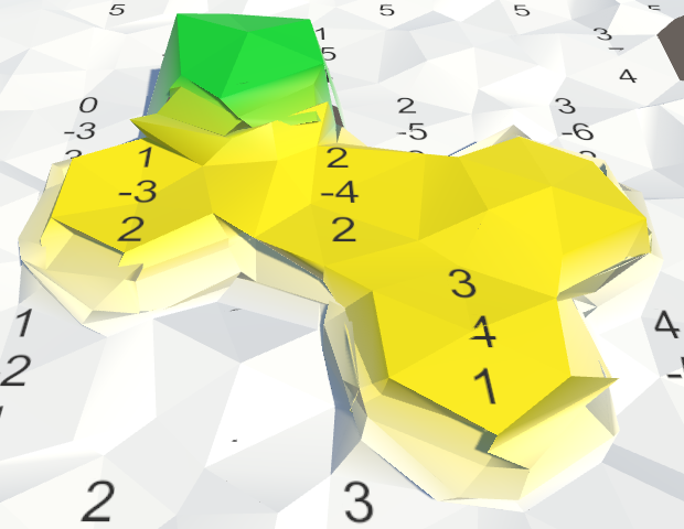
Up to a radius of 3.
To edit cells, you need to go around them in a loop. First we need the X and Z coordinates of the center.
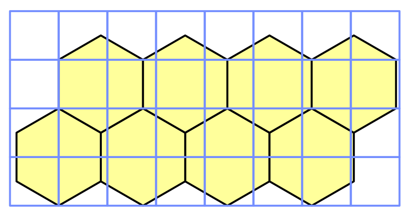
void EditCells (HexCell center) { int centerX = center.coordinates.X; int centerZ = center.coordinates.Z; } We find the minimum Z coordinate by subtracting the radius. So we define the zero string. Starting from this line, we perform a loop until we cover the line in the center.
void EditCells (HexCell center) { int centerX = center.coordinates.X; int centerZ = center.coordinates.Z; for (int r = 0, z = centerZ - brushSize; z <= centerZ; z++, r++) { } } The first cell in the bottom row has the same X coordinate as the center cell. This coordinate decreases as the line number increases.
The last cell always has an X coordinate equal to the center coordinate plus radius.
Now we can loop around each row and get the cells by their coordinates.
for (int r = 0, z = centerZ - brushSize; z <= centerZ; z++, r++) { for (int x = centerX - r; x <= centerX + brushSize; x++) { EditCell(hexGrid.GetCell(new HexCoordinates(x, z))); } } We do not yet have a method
HexGrid.GetCellwith a coordinate parameter, so we will create it. Convert to offset coordinates and get a cell. public HexCell GetCell (HexCoordinates coordinates) { int z = coordinates.Z; int x = coordinates.X + z / 2; return cells[x + z * cellCountX]; } 
The bottom of the brush, size 2.
The rest of the brush we cover, performing a cycle from top to bottom to the center. In this case, the logic is mirrored and the central line must be deleted.
void EditCells (HexCell center) { int centerX = center.coordinates.X; int centerZ = center.coordinates.Z; for (int r = 0, z = centerZ - brushSize; z <= centerZ; z++, r++) { for (int x = centerX - r; x <= centerX + brushSize; x++) { EditCell(hexGrid.GetCell(new HexCoordinates(x, z))); } } for (int r = 0, z = centerZ + brushSize; z > centerZ; z--, r++) { for (int x = centerX - brushSize; x <= centerX + r; x++) { EditCell(hexGrid.GetCell(new HexCoordinates(x, z))); } } } 
The whole brush is size 2.
It works, unless our brush goes beyond the grid. When this happens, we get the index-out-of-range exception. To avoid this, check the boundaries in
HexGrid.GetCelland return nullwhen a non-existing cell is requested. public HexCell GetCell (HexCoordinates coordinates) { int z = coordinates.Z; if (z < 0 || z >= cellCountZ) { return null; } int x = coordinates.X + z / 2; if (x < 0 || x >= cellCountX) { return null; } return cells[x + z * cellCountX]; } To avoid null-reference-exception, you
HexMapEditormust check before editing whether a cell really exists. void EditCell (HexCell cell) { if (cell) { if (applyColor) { cell.Color = activeColor; } if (applyElevation) { cell.Elevation = activeElevation; } } } Use multiple brush sizes.
Toggle visibility of cell labels
Most often, we don’t need to see the labels of the cells. So let's make them optional. Since each fragment controls its own canvas, let's add a method
ShowUIto HexGridChunk. When the UI needs to be visible, we activate canvas. Otherwise, deactivate it. public void ShowUI (bool visible) { gridCanvas.gameObject.SetActive(visible); } Let's hide the UI by default.
void Awake () { gridCanvas = GetComponentInChildren<Canvas>(); hexMesh = GetComponentInChildren<HexMesh>(); cells = new HexCell[HexMetrics.chunkSizeX * HexMetrics.chunkSizeZ]; ShowUI(false); } Since the visibility of the UI switches for the whole map, we will add a method
ShowUIto the HexGrid. He simply sends the request to his fragments. public void ShowUI (bool visible) { for (int i = 0; i < chunks.Length; i++) { chunks[i].ShowUI(visible); } } HexMapEditor gets the same method by passing the request to the grid. public void ShowUI (bool visible) { hexGrid.ShowUI(visible); } Finally, we can add a switch to the UI and connect it.

Switch visibility tags.
unitypackage
Part 6: Rivers
- Adding to the cells of these rivers.
- Drag and drop support for drawing rivers.
- Creation of river channels.
- Use several meshes per fragment.
- Creating a common pool of lists.
- Triangulation and animation of flowing water.
In the previous part, we talked about supporting large cards. Now we can move on to larger scale relief elements. This time we will talk about the rivers.

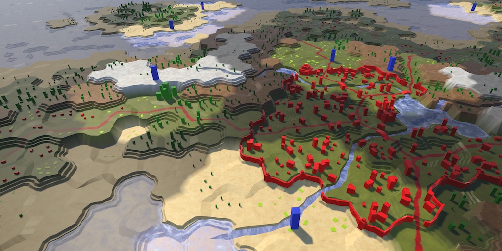
Rivers flow from the mountains.
Cells with rivers
There are three ways to add rivers to a grid of hexagons. The first way is to allow them to flow from cell to cell. This is how it is implemented in Endless Legend. The second way is to allow them to flow between the cells, from the edge to the edge. So it is implemented in Civilization 5. The third way is not to create special structures of rivers at all, but to use water cells to envision them. So the rivers are realized in Age of Wonders 3.
In our case, the edges of the cells are already occupied by slopes and cliffs. This leaves little room for rivers. Therefore, we will make them flow from cell to cell. This means that in each cell there will either be no river, or a river will flow through it, or there will be a beginning or end of a river in it. In those cells through which the river flows, it can flow straight, make a turn one step or two steps.

Five possible configurations of the rivers.
We will not support branching or merging rivers. This will complicate things even more, especially the flow of water. Also, we will not be puzzled by large volumes of water. We will look at them in another tutorial.
River tracking
A cell through which a river flows can be considered at the same time as having an incoming and outgoing river. If it contains the beginning of a river, then it has only the outgoing river. And if it contains the end of a river, then it only has an incoming river. We can store this information in
HexCellusing two boolean values. bool hasIncomingRiver, hasOutgoingRiver; But this is not enough. We also need to know the direction of these rivers. In the case of an outgoing river, it indicates where it is going. In the case of an incoming river, it indicates where it came from.
bool hasIncomingRiver, hasOutgoingRiver; HexDirection incomingRiver, outgoingRiver; We will need this information when triangulating cells, so we’ll add properties to have access to it. We will not support assigning them directly. To do this, we will further add a separate method.
public bool HasIncomingRiver { get { return hasIncomingRiver; } } public bool HasOutgoingRiver { get { return hasOutgoingRiver; } } public HexDirection IncomingRiver { get { return incomingRiver; } } public HexDirection OutgoingRiver { get { return outgoingRiver; } } The important question is whether there is a river in the cell, regardless of the details. So let's add a property for this too.
public bool HasRiver { get { return hasIncomingRiver || hasOutgoingRiver; } } Another logical question is whether the beginning or end of the river is in the cell. If the state of the incoming and outgoing river is different, then this is exactly the case. Therefore, we make this one more property.
public bool HasRiverBeginOrEnd { get { return hasIncomingRiver != hasOutgoingRiver; } } Finally, it will be helpful to know whether a river flows through a certain edge, be it incoming or outgoing.
public bool HasRiverThroughEdge (HexDirection direction) { return hasIncomingRiver && incomingRiver == direction || hasOutgoingRiver && outgoingRiver == direction; } River removal
Before we start adding a river to a cell, let's first implement support for deleting rivers. To begin with, we will write a method for removing only the outgoing part of the river.
If there is no outgoing river in the cell, then nothing needs to be done. Otherwise, disable it and perform the update.
public void RemoveOutgoingRiver () { if (!hasOutgoingRiver) { return; } hasOutgoingRiver = false; Refresh(); } But that is not all.The outgoing river must move somewhere further. Therefore, there must be a neighbor with the incoming river. We need to get rid of her too.
public void RemoveOutgoingRiver () { if (!hasOutgoingRiver) { return; } hasOutgoingRiver = false; Refresh(); HexCell neighbor = GetNeighbor(outgoingRiver); neighbor.hasIncomingRiver = false; neighbor.Refresh(); } Can't a river flow out of a map?
, . , .
Removing a river from a cell changes only the appearance of this cell. Unlike editing height or color, it does not affect neighbors. Therefore, we need to update only the cell itself, but not its neighbors.
public void RemoveOutgoingRiver () { if (!hasOutgoingRiver) { return; } hasOutgoingRiver = false; RefreshSelfOnly(); HexCell neighbor = GetNeighbor(outgoingRiver); neighbor.hasIncomingRiver = false; neighbor.RefreshSelfOnly(); } This method
RefreshSelfOnlysimply updates the fragment to which the cell belongs. Since we do not change the river during grid initialization, we don’t need to worry about whether a fragment has already been assigned. void RefreshSelfOnly () { chunk.Refresh(); } Removing incoming rivers works the same way.
public void RemoveIncomingRiver () { if (!hasIncomingRiver) { return; } hasIncomingRiver = false; RefreshSelfOnly(); HexCell neighbor = GetNeighbor(incomingRiver); neighbor.hasOutgoingRiver = false; neighbor.RefreshSelfOnly(); } And the removal of the entire river simply means the removal of both the incoming and outgoing parts of the river.
public void RemoveRiver () { RemoveOutgoingRiver(); RemoveIncomingRiver(); } Adding rivers
To support the creation of rivers, we need a method for defining the outgoing river of a cell. It must redefine all previous outgoing rivers and set the appropriate incoming river.
For a start, we don’t need to do anything if the river already exists.
public void SetOutgoingRiver (HexDirection direction) { if (hasOutgoingRiver && outgoingRiver == direction) { return; } } Next, we need to make sure that there is a neighbor in the right direction. In addition, rivers can not flow upwards. Therefore, we must complete the operation if the neighbor is higher.
HexCell neighbor = GetNeighbor(direction); if (!neighbor || elevation < neighbor.elevation) { return; } Next we need to clear the previous outgoing river. And also we need to remove the incoming river if it overlaps a new outgoing river.
RemoveOutgoingRiver(); if (hasIncomingRiver && incomingRiver == direction) { RemoveIncomingRiver(); } Now we can proceed to setting up the outgoing river.
hasOutgoingRiver = true; outgoingRiver = direction; RefreshSelfOnly(); And do not forget to set the incoming river for another cell after deleting its current incoming river, if it exists.
neighbor.RemoveIncomingRiver(); neighbor.hasIncomingRiver = true; neighbor.incomingRiver = direction.Opposite(); neighbor.RefreshSelfOnly(); Getting rid of the rivers flowing up
Now that we have made it so that only the right rivers can be added, other actions can still create the wrong ones. When we change the height of the cell, we must again forcefully make sure that the rivers can only flow down. All wrong rivers need to be removed.
public int Elevation { get { return elevation; } set { … if ( hasOutgoingRiver && elevation < GetNeighbor(outgoingRiver).elevation ) { RemoveOutgoingRiver(); } if ( hasIncomingRiver && elevation > GetNeighbor(incomingRiver).elevation ) { RemoveIncomingRiver(); } Refresh(); } } unitypackage
River change
To support river editing, we need to add a river switch to the UI. In fact.we need support for three editing modes. We need to either ignore the rivers, or add them, or delete them. We can use a simple auxiliary listing of switches to track the status. Since we will only use it inside the editor, we can define it inside the class
HexMapEditor, along with the river mode field. enum OptionalToggle { Ignore, Yes, No } OptionalToggle riverMode; And we will need a method to change the mode of the river through the UI.
public void SetRiverMode (int mode) { riverMode = (OptionalToggle)mode; } To control the river mode, add three switches to the UI and connect them to the new toggle group, as we did with the colors. I configured the switches so that their labels are under the flags. Because of this, they will remain thin enough to fit all three options in one line.

UI rec.
Why not use the drop-down list?
, . dropdown list Unity Play. , .
Drag and Drop Recognition
To create a river, we need both a cell and a direction. At the moment
HexMapEditordoes not provide us with this information. Therefore, we need to add drag and drop support from one cell to another.We need to know if this drag will be correct and also determine its direction. And to recognize drag and drop, we need to remember the previous cell.
bool isDrag; HexDirection dragDirection; HexCell previousCell; Initially, when dragging is not performed, there is no previous cell. That is, when there is no input or we do not interact with the map, you need to assign a value to it
null. void Update () { if ( Input.GetMouseButton(0) && !EventSystem.current.IsPointerOverGameObject() ) { HandleInput(); } else { previousCell = null; } } void HandleInput () { Ray inputRay = Camera.main.ScreenPointToRay(Input.mousePosition); RaycastHit hit; if (Physics.Raycast(inputRay, out hit)) { EditCells(hexGrid.GetCell(hit.point)); } else { previousCell = null; } } The current cell is the one we found by intersecting the beam with the mesh. After the cell editing is completed, it is updated and becomes the previous cell for the new update.
void HandleInput () { Ray inputRay = Camera.main.ScreenPointToRay(Input.mousePosition); RaycastHit hit; if (Physics.Raycast(inputRay, out hit)) { HexCell currentCell = hexGrid.GetCell(hit.point); EditCells(currentCell); previousCell = currentCell; } else { previousCell = null; } } After determining the current cell, we can compare it with the previous cell, if it exists. If we get two different cells, then we may have the correct drag and we need to check this. Otherwise, it is not exactly dragging.
if (Physics.Raycast(inputRay, out hit)) { HexCell currentCell = hexGrid.GetCell(hit.point); if (previousCell && previousCell != currentCell) { ValidateDrag(currentCell); } else { isDrag = false; } EditCells(currentCell); previousCell = currentCell; isDrag = true; } How do we check dragging? Checking whether the current cell is a neighbor of the previous one. We check this by circumventing its neighbors in a loop. If we find a match, we also immediately recognize the direction of drag and drop.
void ValidateDrag (HexCell currentCell) { for ( dragDirection = HexDirection.NE; dragDirection <= HexDirection.NW; dragDirection++ ) { if (previousCell.GetNeighbor(dragDirection) == currentCell) { isDrag = true; return; } } isDrag = false; } Do not we create with this dragging drag?
, . «» , .
, . .
, . .
Cell change
Now that we can recognize drag and drop, we can define outgoing rivers. We can also delete rivers, it does not require dragging support.
void EditCell (HexCell cell) { if (cell) { if (applyColor) { cell.Color = activeColor; } if (applyElevation) { cell.Elevation = activeElevation; } if (riverMode == OptionalToggle.No) { cell.RemoveRiver(); } else if (isDrag && riverMode == OptionalToggle.Yes) { previousCell.SetOutgoingRiver(dragDirection); } } } This code will draw the river from the previous cell to the current one. But he ignores the size of the brush. This is quite logical, but let's draw the rivers for all cells covered with a brush. This can be done by performing operations on the edited cell. In our case, we need to make sure that another cell really exists.
else if (isDrag && riverMode == OptionalToggle.Yes) { HexCell otherCell = cell.GetNeighbor(dragDirection.Opposite()); if (otherCell) { otherCell.SetOutgoingRiver(dragDirection); } } Now we can edit the rivers, but we don’t see them yet. We can verify that this works by examining the altered cells in the debugger inspector.

Cell with river in the debug inspector.
What is a debug inspector?
. . , .
unitypackage
Riverbed between cells
During river triangulation, we need to take into account two parts: the location of the river bed and the water flowing through it. First, we will create a channel, and leave water for later.
The simplest part of the river is where it flows in the junctions between the cells. For the time being we triangulate this area with a strip of three quad. We can add to it the riverbed, lowering the middle quad and adding two walls of the channel.

Adding river to the rib strip.
For this, in the case of a river, two additional quad will be required and a channel with two vertical walls will be created. An alternative approach is to use four quad. Then we will lower the middle top to create a bed with sloping walls.

Always four quad.
Constant use of the same number of quadrilaterals is convenient, so let's choose this option.
Adding a vertex edge
The transition from three to four per edge requires the creation of an additional vertex of the edge. Rewrite
EdgeVertices, first rename v4to v5, and then rename v3to v4. Actions in this order ensure that all code will continue to refer to the correct vertices. Use the rename or refactor option of your editor to apply the changes everywhere. Otherwise, you will have to manually inspect the entire code and make changes. public Vector3 v1, v2, v4, v5; After renaming everything, add a new one
v3. public Vector3 v1, v2, v3, v4, v5; Add a new vertex to the constructor. It is located in the middle between the corner vertices. In addition, the other vertices should now be in ½ and ¾, and not in & frac13; and & frac23 ;.
public EdgeVertices (Vector3 corner1, Vector3 corner2) { v1 = corner1; v2 = Vector3.Lerp(corner1, corner2, 0.25f); v3 = Vector3.Lerp(corner1, corner2, 0.5f); v4 = Vector3.Lerp(corner1, corner2, 0.75f); v5 = corner2; } Add
v3and in TerraceLerp. public static EdgeVertices TerraceLerp ( EdgeVertices a, EdgeVertices b, int step) { EdgeVertices result; result.v1 = HexMetrics.TerraceLerp(a.v1, b.v1, step); result.v2 = HexMetrics.TerraceLerp(a.v2, b.v2, step); result.v3 = HexMetrics.TerraceLerp(a.v3, b.v3, step); result.v4 = HexMetrics.TerraceLerp(a.v4, b.v4, step); result.v5 = HexMetrics.TerraceLerp(a.v5, b.v5, step); return result; } Now I
HexMeshneed to include an additional vertex in the fans of the edge triangles. void TriangulateEdgeFan (Vector3 center, EdgeVertices edge, Color color) { AddTriangle(center, edge.v1, edge.v2); AddTriangleColor(color); AddTriangle(center, edge.v2, edge.v3); AddTriangleColor(color); AddTriangle(center, edge.v3, edge.v4); AddTriangleColor(color); AddTriangle(center, edge.v4, edge.v5); AddTriangleColor(color); } And also in his strip of quadrangles.
void TriangulateEdgeStrip ( EdgeVertices e1, Color c1, EdgeVertices e2, Color c2 ) { AddQuad(e1.v1, e1.v2, e2.v1, e2.v2); AddQuadColor(c1, c2); AddQuad(e1.v2, e1.v3, e2.v2, e2.v3); AddQuadColor(c1, c2); AddQuad(e1.v3, e1.v4, e2.v3, e2.v4); AddQuadColor(c1, c2); AddQuad(e1.v4, e1.v5, e2.v4, e2.v5); AddQuadColor(c1, c2); } 

Comparison of four and five vertices per edge.
The height of the river bed
We created the channel by dropping the bottom edge of the edge. It determines the vertical position of the river bed. Although the exact vertical position of each cell is distorted, we must maintain the same height of the river bed in the cells with the same height. Thanks to this water will not have to flow upstream. In addition, the bed should be low enough to remain at the bottom, even in the case of the most vertical cells deviating at the same time, leaving enough space for water.
Let's set this offset in
HexMetricsand express it as height. Offsets one level will suffice. public const float streamBedElevationOffset = -1f; We can use this metric to add properties
HexCellto get the vertical position of the river bed of the cell. public float StreamBedY { get { return (elevation + HexMetrics.streamBedElevationOffset) * HexMetrics.elevationStep; } } Creating a channel
When
HexMeshone of the six triangular parts of a cell triangulates, we can determine if a river flows along its edge. If so, then we can lower the middle edge of the rib to the height of the river bed. void Triangulate (HexDirection direction, HexCell cell) { Vector3 center = cell.Position; EdgeVertices e = new EdgeVertices( center + HexMetrics.GetFirstSolidCorner(direction), center + HexMetrics.GetSecondSolidCorner(direction) ); if (cell.HasRiverThroughEdge(direction)) { e.v3.y = cell.StreamBedY; } TriangulateEdgeFan(center, e, cell.Color); if (direction <= HexDirection.SE) { TriangulateConnection(direction, cell, e); } } 
Change the average vertex of the edge.
We can see the first signs of the river appear, but at the same time holes in the relief appear. To close them, we need to change the other edge and then triangulate the connection.
void TriangulateConnection ( HexDirection direction, HexCell cell, EdgeVertices e1 ) { HexCell neighbor = cell.GetNeighbor(direction); if (neighbor == null) { return; } Vector3 bridge = HexMetrics.GetBridge(direction); bridge.y = neighbor.Position.y - cell.Position.y; EdgeVertices e2 = new EdgeVertices( e1.v1 + bridge, e1.v5 + bridge ); if (cell.HasRiverThroughEdge(direction)) { e2.v3.y = neighbor.StreamBedY; } … } 
Finished channels of rib connections.
unitypackage
Riverbeds passing through the cell
Now we have the right riverbeds between the cells. But when a river flows through a cell, the channels always end at its center. To solve this problem will have to work. Let's start with the case when the river flows directly through the cell, from one edge to the opposite.
If there is no river, then each part of the cell can be a simple fan of triangles. But when the river flows directly, it is necessary to insert the channel. In fact, we need to stretch the central vertex into a line, thus turning the middle two triangles into quadrilaterals. Then the fan of triangles turns into a trapezoid.

Insert the channel into the triangle.
Such channels will be much longer than passing through the cell connections. This becomes apparent when the positions of the vertices are distorted. So let's divide the trapezoid into two segments by inserting another set of edge vertices in the middle between the center and the edge.

Channel triangulation.
Since triangulation with a river will be very different from triangulation without a river, let's create a separate method for it. If we have a river, then we use this method, and otherwise we will leave a fan of triangles.
void Triangulate (HexDirection direction, HexCell cell) { Vector3 center = cell.Position; EdgeVertices e = new EdgeVertices( center + HexMetrics.GetFirstSolidCorner(direction), center + HexMetrics.GetSecondSolidCorner(direction) ); if (cell.HasRiver) { if (cell.HasRiverThroughEdge(direction)) { e.v3.y = cell.StreamBedY; TriangulateWithRiver(direction, cell, center, e); } } else { TriangulateEdgeFan(center, e, cell.Color); } if (direction <= HexDirection.SE) { TriangulateConnection(direction, cell, e); } } void TriangulateWithRiver ( HexDirection direction, HexCell cell, Vector3 center, EdgeVertices e ) { } 
Holes in which there must be rivers.
To better see what is happening, temporarily disable cell distortion.
public const float cellPerturbStrength = 0f; // 4f; 
Undistorted vertices.
Triangulation directly through the cell
To create the channel directly through part of the cell, we must stretch the center in a line. This line should have the same width as the channel. We can find the left vertex by moving ¼ the distance from the center to the first corner of the previous part.
void TriangulateWithRiver ( HexDirection direction, HexCell cell, Vector3 center, EdgeVertices e ) { Vector3 centerL = center + HexMetrics.GetFirstSolidCorner(direction.Previous()) * 0.25f; } Similarly for the right vertex. In this case, we need the second corner of the next part.
Vector3 centerL = center + HexMetrics.GetFirstSolidCorner(direction.Previous()) * 0.25f; Vector3 centerR = center + HexMetrics.GetSecondSolidCorner(direction.Next()) * 0.25f; The middle line can be found by creating vertices of the edge between the center and the edge.
EdgeVertices m = new EdgeVertices( Vector3.Lerp(centerL, e.v1, 0.5f), Vector3.Lerp(centerR, e.v5, 0.5f) ); Next, we change the middle vertex of the middle edge, as well as the center, because they will become the lower points of the channel.
m.v3.y = center.y = e.v3.y; Now we can use
TriangulateEdgeStripto fill the space between the middle line and the edge line. TriangulateEdgeStrip(m, cell.Color, e, cell.Color); 
Compressed bed.
Unfortunately, the river beds look compressed. This happens because the middle vertices of the edge are too close to each other. Why did it happen so?
If we assume that the length of the outer edge is 1, then the length of the center line will be ½. Since the middle edge is in the middle between them, its length should be equal to ¾.
The width of the channel is ½ and must remain constant. Since the length of the average edge is, then only ¼ remains, according to & frac18; on both sides of the channel.

Relative lengths
Since the length of the average edge is ¾, then & frac18; becomes relative to the length of the average edge & frac16 ;. This means that its second and fourth vertices should be interpolated with sixths, not quarters.
We can provide support for this alternative interpolation by adding
EdgeVerticesone more constructor. Instead of fixed interpolations for v2and v4let's use the parameter. public EdgeVertices (Vector3 corner1, Vector3 corner2, float outerStep) { v1 = corner1; v2 = Vector3.Lerp(corner1, corner2, outerStep); v3 = Vector3.Lerp(corner1, corner2, 0.5f); v4 = Vector3.Lerp(corner1, corner2, 1f - outerStep); v5 = corner2; } Now we can use it with & frac16; in
HexMesh.TriangulateWithRiver. EdgeVertices m = new EdgeVertices( Vector3.Lerp(centerL, e.v1, 0.5f), Vector3.Lerp(centerR, e.v5, 0.5f), 1f / 6f ); 
Straight channel.
Making the course straight, we can go to the second part of the trapezoid. In this case, we cannot use the edge strip, so we have to do it manually. Let's first create triangles on the sides.
AddTriangle(centerL, m.v1, m.v2); AddTriangleColor(cell.Color); AddTriangle(centerR, m.v4, m.v5); AddTriangleColor(cell.Color); 
Side triangles.
It looks good, so let's fill the remaining space with two quadrilaterals, creating the last part of the channel.
AddTriangle(centerL, m.v1, m.v2); AddTriangleColor(cell.Color); AddQuad(centerL, center, m.v2, m.v3); AddQuadColor(cell.Color); AddQuad(center, centerR, m.v3, m.v4); AddQuadColor(cell.Color); AddTriangle(centerR, m.v4, m.v5); AddTriangleColor(cell.Color); In fact, we do not have an alternative
AddQuadColorthat requires only one parameter. While we did not need it. So let's create it. void AddQuadColor (Color color) { colors.Add(color); colors.Add(color); colors.Add(color); colors.Add(color); } 
Completed straight channel.
Start and End Triangulation
Triangulation of a part that has only the beginning or end of a river is quite different, therefore it requires its own method. Therefore, we will check this in
Triangulateand call the appropriate method. if (cell.HasRiver) { if (cell.HasRiverThroughEdge(direction)) { e.v3.y = cell.StreamBedY; if (cell.HasRiverBeginOrEnd) { TriangulateWithRiverBeginOrEnd(direction, cell, center, e); } else { TriangulateWithRiver(direction, cell, center, e); } } } In this case, we want to complete the channel in the center, but we still use two stages for this. Therefore, we will again create a middle edge between the center or edge. Since we want to complete the channel, we are quite satisfied that it will be compressed.
void TriangulateWithRiverBeginOrEnd ( HexDirection direction, HexCell cell, Vector3 center, EdgeVertices e ) { EdgeVertices m = new EdgeVertices( Vector3.Lerp(center, e.v1, 0.5f), Vector3.Lerp(center, e.v5, 0.5f) ); } So that the channel does not become shallow too quickly, we still assign the height of the river bed to the middle peak. But the center does not need to be changed.
m.v3.y = e.v3.y; We can triangulate with one strip of rib and fan.
TriangulateEdgeStrip(m, cell.Color, e, cell.Color); TriangulateEdgeFan(center, m, cell.Color); 
The points start and end.
Turns in one step
Next, we consider sharp turns, which zigzag pass between adjacent cells. We will process them too
TriangulateWithRiver. Therefore, we need to determine what type of river we are working with.
A zigzag river.
If the cell has a river flowing in the opposite direction, as well as in the direction we are working with, then it must be a direct river. In this case, we can keep the center line, which we have already calculated. Otherwise, it returns to one point, folding the center line.
Vector3 centerL, centerR; if (cell.HasRiverThroughEdge(direction.Opposite())) { centerL = center + HexMetrics.GetFirstSolidCorner(direction.Previous()) * 0.25f; centerR = center + HexMetrics.GetSecondSolidCorner(direction.Next()) * 0.25f; } else { centerL = centerR = center; } 
Convolving zigzags.
We can recognize sharp turns by checking whether a cell has a river passing through the next or previous part of the cell. If there is, then we need to align the center line with the edge between this and the next part. We can do this by placing the corresponding side of the line in the middle between the center and the total angle. The other side of the line then becomes the center.
if (cell.HasRiverThroughEdge(direction.Opposite())) { centerL = center + HexMetrics.GetFirstSolidCorner(direction.Previous()) * 0.25f; centerR = center + HexMetrics.GetSecondSolidCorner(direction.Next()) * 0.25f; } else if (cell.HasRiverThroughEdge(direction.Next())) { centerL = center; centerR = Vector3.Lerp(center, e.v5, 0.5f); } else if (cell.HasRiverThroughEdge(direction.Previous())) { centerL = Vector3.Lerp(center, e.v1, 0.5f); centerR = center; } else { centerL = centerR = center; } By deciding where the left and right points are, we can determine the resulting center by their averaging.
if (cell.HasRiverThroughEdge(direction.Opposite())) { … } center = Vector3.Lerp(centerL, centerR, 0.5f); 
Offset central rib.
Although the channel has the same width on both sides, it looks quite compressed. This is caused by a 60 ° rotation of the center line. You can smooth this effect by slightly increasing the width of the center line. Instead of interpolating with ½, use & frac23 ;.
else if (cell.HasRiverThroughEdge(direction.Next())) { centerL = center; centerR = Vector3.Lerp(center, e.v5, 2f / 3f); } else if (cell.HasRiverThroughEdge(direction.Previous())) { centerL = Vector3.Lerp(center, e.v1, 2f / 3f); centerR = center; } 
Zigzag without compression.
Two-step turns
The remaining cases are between zigzags and straight rivers. These are two-stage turns, creating gently curving rivers.

Winding river.
To distinguish between two possible orientations, we need to use
direction.Next().Next(). But let's make it more convenient by adding HexDirectionextension methods Next2and Previous2. public static HexDirection Previous2 (this HexDirection direction) { direction -= 2; return direction >= HexDirection.NE ? direction : (direction + 6); } public static HexDirection Next2 (this HexDirection direction) { direction += 2; return direction <= HexDirection.NW ? direction : (direction - 6); } Let's go back to
HexMesh.TriangulateWithRiver. Now we can recognize the direction of our meandering river with the help direction.Next2(). if (cell.HasRiverThroughEdge(direction.Opposite())) { centerL = center + HexMetrics.GetFirstSolidCorner(direction.Previous()) * 0.25f; centerR = center + HexMetrics.GetSecondSolidCorner(direction.Next()) * 0.25f; } else if (cell.HasRiverThroughEdge(direction.Next())) { centerL = center; centerR = Vector3.Lerp(center, e.v5, 2f / 3f); } else if (cell.HasRiverThroughEdge(direction.Previous())) { centerL = Vector3.Lerp(center, e.v1, 2f / 3f); centerR = center; } else if (cell.HasRiverThroughEdge(direction.Next2())) { centerL = centerR = center; } else { centerL = centerR = center; } In these last two cases, we need to shift the center line to the part of the cell that is located on the inside of the curve. If we had a vector to the middle of a solid edge, then we could use it to position the end point. Let's imagine that we have a method for this.
else if (cell.HasRiverThroughEdge(direction.Next2())) { centerL = center; centerR = center + HexMetrics.GetSolidEdgeMiddle(direction.Next()) * 0.5f; } else { centerL = center + HexMetrics.GetSolidEdgeMiddle(direction.Previous()) * 0.5f; centerR = center; } Of course, now we need to add such a method in
HexMetrics. It simply has to average two vectors of adjacent angles and apply the coefficient of wholeness. public static Vector3 GetSolidEdgeMiddle (HexDirection direction) { return (corners[(int)direction] + corners[(int)direction + 1]) * (0.5f * solidFactor); } 
Slightly compressed curves.
Our center lines are now correctly rotated 30 °. But they are not long enough, because of which the channel is slightly compressed. This happens because the midpoint of the edge is closer to the center than the angle of the edge. Its distance is equal to the inner radius, not the outer one. That is, we are working with the wrong scale.
We are already converting from external to internal radius in
HexMetrics. We need to perform the reverse operation. So let's make both conversion factors available via HexMetrics. public const float outerToInner = 0.866025404f; public const float innerToOuter = 1f / outerToInner; public const float outerRadius = 10f; public const float innerRadius = outerRadius * outerToInner; Now we can go to the right scale in
HexMesh.TriangulateWithRiver. Channels will still remain slightly compressed due to their rotation, but this is much less pronounced than in the case of zigzags. Therefore, we do not need to compensate for this. else if (cell.HasRiverThroughEdge(direction.Next2())) { centerL = center; centerR = center + HexMetrics.GetSolidEdgeMiddle(direction.Next()) * (0.5f * HexMetrics.innerToOuter); } else { centerL = center + HexMetrics.GetSolidEdgeMiddle(direction.Previous()) * (0.5f * HexMetrics.innerToOuter); centerR = center; } 
Smooth curves.
unitypackage
River triangulation
Our rivers are ready. But we have not yet triangulated other parts of the cells containing rivers. Now we will close these holes.

Holes near the channels.
If a cell has a river, but it does not flow in the current direction, then
Triangulatewe will call a new method. if (cell.HasRiver) { if (cell.HasRiverThroughEdge(direction)) { e.v3.y = cell.StreamBedY; if (cell.HasRiverBeginOrEnd) { TriangulateWithRiverBeginOrEnd(direction, cell, center, e); } else { TriangulateWithRiver(direction, cell, center, e); } } else { TriangulateAdjacentToRiver(direction, cell, center, e); } } else { TriangulateEdgeFan(center, e, cell.Color); } In this method, we fill the triangle of the cell with a stripe and a fan. Only a fan will not be enough for us, because the tops must correspond to the middle edge of the parts containing the river.
void TriangulateAdjacentToRiver ( HexDirection direction, HexCell cell, Vector3 center, EdgeVertices e ) { EdgeVertices m = new EdgeVertices( Vector3.Lerp(center, e.v1, 0.5f), Vector3.Lerp(center, e.v5, 0.5f) ); TriangulateEdgeStrip(m, cell.Color, e, cell.Color); TriangulateEdgeFan(center, m, cell.Color); } 
Overlay in curves and straight rivers.
Match the course
Of course, we need to make sure that the center we use corresponds to the central part used by the parts with the river. With zigzags, everything is in order, and the curves and straight rivers need attention. Therefore, we need to determine both the type of the river and its relative orientation.
Let's start by checking whether we are inside the curve. In this case, both the previous and the next direction contain the river. If so, then we need to move the center to the edge.
if (cell.HasRiverThroughEdge(direction.Next())) { if (cell.HasRiverThroughEdge(direction.Previous())) { center += HexMetrics.GetSolidEdgeMiddle(direction) * (HexMetrics.innerToOuter * 0.5f); } } EdgeVertices m = new EdgeVertices( Vector3.Lerp(center, e.v1, 0.5f), Vector3.Lerp(center, e.v5, 0.5f) ); 
Fixed a case where the river flows on both sides.
If we have a river in a different direction, but not in the previous one, then we check whether it is direct. If so, then move the center to the first corner.
if (cell.HasRiverThroughEdge(direction.Next())) { if (cell.HasRiverThroughEdge(direction.Previous())) { center += HexMetrics.GetSolidEdgeMiddle(direction) * (HexMetrics.innerToOuter * 0.5f); } else if ( cell.HasRiverThroughEdge(direction.Previous2()) ) { center += HexMetrics.GetFirstSolidCorner(direction) * 0.25f; } } 
Fixed half overlap with straight river.
So we solved the problem with half of the parts adjacent to straight rivers. The last case - we have a river in the previous direction, and it is direct. At the same time you need to move the center to the next corner.
if (cell.HasRiverThroughEdge(direction.Next())) { if (cell.HasRiverThroughEdge(direction.Previous())) { center += HexMetrics.GetSolidEdgeMiddle(direction) * (HexMetrics.innerToOuter * 0.5f); } else if ( cell.HasRiverThroughEdge(direction.Previous2()) ) { center += HexMetrics.GetFirstSolidCorner(direction) * 0.25f; } } else if ( cell.HasRiverThroughEdge(direction.Previous()) && cell.HasRiverThroughEdge(direction.Next2()) ) { center += HexMetrics.GetSecondSolidCorner(direction) * 0.25f; } 
No more overlays.
unitypackage
HexMesh summary
We have completed the triangulation of the channels. Now we can fill them with water. Since water is different from sushi, we will need to use a different mesh with different vertex data and different material. It would be quite convenient if we could use
HexMeshboth for sushi and water. So let's summarize HexMesh, turning it into a class that deals with these meshes, regardless of what it is used for. The task of the triangulation of its cells, we pass HexGridChunk.Perturb method relocation
Since the method is
Perturbfairly generalized and will be used in different places, let's move it to HexMetrics. First, rename it to HexMetrics.Perturb. This is the wrong method name, but it refactor all the code to use it correctly. If your code editor has a special functionality for moving methods, then use it.Moving the method inside
HexMetrics, make it general and static, and then correct its name. public static Vector3 Perturb (Vector3 position) { Vector4 sample = SampleNoise(position); position.x += (sample.x * 2f - 1f) * cellPerturbStrength; position.z += (sample.z * 2f - 1f) * cellPerturbStrength; return position; } Moving triangulation methods
In
HexGridChunkreplace the variable hexMeshto a common variable terrain. public HexMesh terrain; // HexMesh hexMesh; void Awake () { gridCanvas = GetComponentInChildren<Canvas>(); // hexMesh = GetComponentInChildren<HexMesh>(); cells = new HexCell[HexMetrics.chunkSizeX * HexMetrics.chunkSizeZ]; ShowUI(false); } Further we will execute refactoring of all methods
Add…from HexMeshc terrain.Add…. Then move all the methods Triangulate…to HexGridChunk. After that, you can correct the names of the methods Add…in HexMeshand make them common. As a result, all complex triangulation methods will be found HexGridChunk, and simple methods for adding data to the mesh will remain in HexMesh.We haven't finished yet. Now
HexGridChunk.LateUpdatemust call its own method Triangulate. In addition, it should no longer pass cells as an argument. Therefore, it Triangulatecan lose its parameter. And it must delegate the cleanup and application of the mesh data HexMesh. void LateUpdate () { Triangulate(); // hexMesh.Triangulate(cells); enabled = false; } public void Triangulate () { terrain.Clear(); // hexMesh.Clear(); // vertices.Clear(); // colors.Clear(); // triangles.Clear(); for (int i = 0; i < cells.Length; i++) { Triangulate(cells[i]); } terrain.Apply(); // hexMesh.vertices = vertices.ToArray(); // hexMesh.colors = colors.ToArray(); // hexMesh.triangles = triangles.ToArray(); // hexMesh.RecalculateNormals(); // meshCollider.sharedMesh = hexMesh; } Add the required methods
Clearand Applyin HexMesh. public void Clear () { hexMesh.Clear(); vertices.Clear(); colors.Clear(); triangles.Clear(); } public void Apply () { hexMesh.SetVertices(vertices); hexMesh.SetColors(colors); hexMesh.SetTriangles(triangles, 0); hexMesh.RecalculateNormals(); meshCollider.sharedMesh = hexMesh; } What about SetVertices, SetColors and SetTriangles?
Mesh . . , .SetTriangles integer, . , .Finally, manually attach the child object of the mesh to the fragment prefab. We can no longer do this automatically, because we will soon add a second child of the mesh. Rename it to Terrain to designate its purpose.

Assign relief.
Renaming child prefab not working?
. , . , Apply , . .
Creating list pools
Although we moved quite a lot of code, our map still needs to work the same way as before. Adding one more mesh to the fragment will not change this. But if we do this with the present
HexMesh, then errors can occur.The problem is that we assumed that we would work with only one mesh at a time. This allowed us to use static lists for storing temporary mesh data. But after adding water, we will simultaneously work with two meshes, so we can no longer use static lists.
However, we will not return to the sets of lists for each instance
HexMesh. Instead, we use a static pool of lists. By default, such a pooling does not exist, so let's start by creating a common list pool class for ourselves. public static class ListPool<T> { } How does ListPool <T> work?
,
List<int> . <T> ListPool , , . , T ( template).We can use a stack to store a collection of lists in a pool. I usually don't use lists, because Unity does not serialize them, but in this case it doesn't matter.
using System.Collections.Generic; public static class ListPool<T> { static Stack<List<T>> stack = new Stack<List<T>>(); } What does Stack <List <T >> mean?
. , . .
Add a generic static method to get the list from the pool. If the stack is not empty, we will retrieve the top list and return this one. Otherwise, we will create a new list in place.
public static List<T> Get () { if (stack.Count > 0) { return stack.Pop(); } return new List<T>(); } To reuse lists, you need to add them to the pool after you finish working with them.
ListPoolwill be engaged in cleaning the list and writing it to the stack. public static void Add (List<T> list) { list.Clear(); stack.Push(list); } Now we can use pools in
HexMesh. Replace static lists with non-static private links. We mark them as NonSerializedso that Unity does not preserve them during recompilation. Either write System.NonSerializedor add using System;at the beginning of the script. [NonSerialized] List<Vector3> vertices; [NonSerialized] List<Color> colors; [NonSerialized] List<int> triangles; // static List<Vector3> vertices = new List<Vector3>(); // static List<Color> colors = new List<Color>(); // static List<int> triangles = new List<int>(); Since the mesh is cleared right before adding new data to it, this is where you need to get lists from pools.
public void Clear () { hexMesh.Clear(); vertices = ListPool<Vector3>.Get(); colors = ListPool<Color>.Get(); triangles = ListPool<int>.Get(); } After applying these meshes, we no longer need them, so here we can add them to the pools.
public void Apply () { hexMesh.SetVertices(vertices); ListPool<Vector3>.Add(vertices); hexMesh.SetColors(colors); ListPool<Color>.Add(colors); hexMesh.SetTriangles(triangles, 0); ListPool<int>.Add(triangles); hexMesh.RecalculateNormals(); meshCollider.sharedMesh = hexMesh; } So we implemented the reuse of lists regardless of how many meshes we fill at the same time.
Optional Collider
Although our relief needs a collider, for rivers it is not really required. Rays will simply pass through the water and intersect with the channel below it. Let's make it so that you can adjust the presence of the collider for
HexMesh. We implement this by adding a common field bool useCollider. For relief we will turn it on. public bool useCollider; 
Using the mesh collider.
We need to make sure that the collider is created and assigned only when it is turned on.
void Awake () { GetComponent<MeshFilter>().mesh = hexMesh = new Mesh(); if (useCollider) { meshCollider = gameObject.AddComponent<MeshCollider>(); } hexMesh.name = "Hex Mesh"; } public void Apply () { … if (useCollider) { meshCollider.sharedMesh = hexMesh; } … } Optional colors
Vertex colors may also be optional. We need them to demonstrate various types of relief, but water does not change color. We can make them optional just as the collider did optional.
public bool useCollider, useColors; public void Clear () { hexMesh.Clear(); vertices = ListPool<Vector3>.Get(); if (useColors) { colors = ListPool<Color>.Get(); } triangles = ListPool<int>.Get(); } public void Apply () { hexMesh.SetVertices(vertices); ListPool<Vector3>.Add(vertices); if (useColors) { hexMesh.SetColors(colors); ListPool<Color>.Add(colors); } … } Of course, the relief should use the colors of the vertices, so turn them on.

The use of colors.
Optional UV
While we are doing this, you can also add support for optional UV coordinates. Although the relief does not use them, we will need them for water.
public bool useCollider, useColors, useUVCoordinates; [NonSerialized] List<Vector2> uvs; public void Clear () { hexMesh.Clear(); vertices = ListPool<Vector3>.Get(); if (useColors) { colors = ListPool<Color>.Get(); } if (useUVCoordinates) { uvs = ListPool<Vector2>.Get(); } triangles = ListPool<int>.Get(); } public void Apply () { hexMesh.SetVertices(vertices); ListPool<Vector3>.Add(vertices); if (useColors) { hexMesh.SetColors(colors); ListPool<Color>.Add(colors); } if (useUVCoordinates) { hexMesh.SetUVs(0, uvs); ListPool<Vector2>.Add(uvs); } … } 
We do not use UV-coordinates.
To use this function, create methods to add UV coordinates to triangles and quadrilaterals.
public void AddTriangleUV (Vector2 uv1, Vector2 uv2, Vector3 uv3) { uvs.Add(uv1); uvs.Add(uv2); uvs.Add(uv3); } public void AddQuadUV (Vector2 uv1, Vector2 uv2, Vector3 uv3, Vector3 uv4) { uvs.Add(uv1); uvs.Add(uv2); uvs.Add(uv3); uvs.Add(uv4); } Let's add an extra method
AddQuadUVto easily add a rectangular UV area. This is the standard case when the quad and its texture match, we will use it for the water of the river. public void AddQuadUV (float uMin, float uMax, float vMin, float vMax) { uvs.Add(new Vector2(uMin, vMin)); uvs.Add(new Vector2(uMax, vMin)); uvs.Add(new Vector2(uMin, vMax)); uvs.Add(new Vector2(uMax, vMax)); } unitypackage
Flowing rivers
Finally it is time to create water! We will do this with a quad, which will mark the surface of the water. And as we work with rivers, the water must flow. To do this, we use UV-coordinates, indicating the orientation of the river. To visualize this, we need a new shader. Therefore, we will create a new standard shader and name it River . Change it so that the UV coordinates are recorded in the green and red channels of albedo.
Shader "Custom/River" { … void surf (Input IN, inout SurfaceOutputStandard o) { fixed4 c = tex2D(_MainTex, IN.uv_MainTex) * _Color; o.Albedo = c.rgb * IN.color; o.Metallic = _Metallic; o.Smoothness = _Glossiness; o.Alpha = ca; o.Albedo.rg = IN.uv_MainTex; } ENDCG } FallBack "Diffuse" } Add to the
HexGridChunkgeneral field HexMesh rivers. Clear and apply it the same way as in the case of relief. public HexMesh terrain, rivers; public void Triangulate () { terrain.Clear(); rivers.Clear(); for (int i = 0; i < cells.Length; i++) { Triangulate(cells[i]); } terrain.Apply(); rivers.Apply(); } Will we have additional drawing challenges, even if we don't have rivers?
Unity , . , - .
Change the prefab (through the instance) by duplicating its relief object, renaming it to Rivers and connecting it.


Prefab fragment with rivers.
Create the River material using our new shader and make it use the Rivers object . We also configure the object's mesh component of the hexagons so that it uses the UV coordinates, but does not use the vertex colors or the collider.

Sub-object Rivers.
Triangulate water
Before we can triangulate water, we need to determine the level of its surface. Let's make it a height shift
HexMetricsas we did with the bed of the river. Since the vertical distortion of the cell is equal to half the height offset, let's use it to offset the surface of the river. So we guarantee that water will never be above the topography of the cell. public const float riverSurfaceElevationOffset = -0.5f; Why not make it a little lower?
, . , .
Add a
HexCellproperty to get the vertical position of the surface of its river. public float RiverSurfaceY { get { return (elevation + HexMetrics.riverSurfaceElevationOffset) * HexMetrics.elevationStep; } } Now we can get to work at
HexGridChunk! As we will create many quadrangles of rivers, let's add a separate method for this. Let's give it four vertices and a height as parameters. This will allow us to conveniently set the vertical position of all four vertices simultaneously before adding a quad. void TriangulateRiverQuad ( Vector3 v1, Vector3 v2, Vector3 v3, Vector3 v4, float y ) { v1.y = v2.y = v3.y = v4.y = y; rivers.AddQuad(v1, v2, v3, v4); } We will add here the UV coordinates of the quad. Just go around from left to right and from bottom to top.
rivers.AddQuad(v1, v2, v3, v4); rivers.AddQuadUV(0f, 1f, 0f, 1f); TriangulateWithRiver- This is the first method to which we will add quadrangles of rivers. The first quad is between the center and the middle. The second is between the middle and the edge. We just use the vertices that we already have. Since these peaks will be understated, the water as a result will be partially under the sloping walls of the channel. Therefore, we do not need to worry about the exact position of the water edge. void TriangulateWithRiver ( HexDirection direction, HexCell cell, Vector3 center, EdgeVertices e ) { … TriangulateRiverQuad(centerL, centerR, m.v2, m.v4, cell.RiverSurfaceY); TriangulateRiverQuad(m.v2, m.v4, e.v2, e.v4, cell.RiverSurfaceY); } 
The first signs of water.
Why does the width of the water change?
, , — . . .
Moving with the flow
Currently, UV-coordinates are not consistent with the direction of the river. We need to maintain consistency here. Suppose the U coordinate is 0 on the left side of the river, and 1 on the right, when looking downstream. And the V coordinate should vary from 0 to 1 in the direction of the flow of the river.
When using this specification, UV will be correct when triangulating the outgoing river, but will be incorrect and will need to be turned over when the incoming river is triangulated. To simplify the work, add to the
TriangulateRiverQuadparameter bool reversed. Use it to invert the UV if necessary. void TriangulateRiverQuad ( Vector3 v1, Vector3 v2, Vector3 v3, Vector3 v4, float y, bool reversed ) { v1.y = v2.y = v3.y = v4.y = y; rivers.AddQuad(v1, v2, v3, v4); if (reversed) { rivers.AddQuadUV(1f, 0f, 1f, 0f); } else { rivers.AddQuadUV(0f, 1f, 0f, 1f); } } As
TriangulateWithRiverwe know that we need to turn the direction, when dealing with incoming river. bool reversed = cell.IncomingRiver == direction; TriangulateRiverQuad( centerL, centerR, m.v2, m.v4, cell.RiverSurfaceY, reversed ); TriangulateRiverQuad( m.v2, m.v4, e.v2, e.v4, cell.RiverSurfaceY, reversed ); 
The agreed direction of the rivers.
The beginning and the end of the river
Inside,
TriangulateWithRiverBeginOrEndwe only need to check if we have an incoming river to determine the direction of flow. Then we can insert another quad river between the middle and the edge. void TriangulateWithRiverBeginOrEnd ( HexDirection direction, HexCell cell, Vector3 center, EdgeVertices e ) { … bool reversed = cell.HasIncomingRiver; TriangulateRiverQuad( m.v2, m.v4, e.v2, e.v4, cell.RiverSurfaceY, reversed ); } The part between the center and the middle is a triangle, so we cannot use it
TriangulateRiverQuad. The only significant difference here is that the central peak is in the middle of the river. Therefore, its U coordinate is always ½. center.y = m.v2.y = m.v4.y = cell.RiverSurfaceY; rivers.AddTriangle(center, m.v2, m.v4); if (reversed) { rivers.AddTriangleUV( new Vector2(0.5f, 1f), new Vector2(1f, 0f), new Vector2(0f, 0f) ); } else { rivers.AddTriangleUV( new Vector2(0.5f, 0f), new Vector2(0f, 1f), new Vector2(1f, 1f) ); } 
Water at the beginning and end.
Are there any missing parts at the ends?
, quad , . . .
, . , . .
, . , . .
Flow between cells
When adding water between cells, we need to be careful about the height difference. In order for water to flow down slopes and cliffs, it
TriangulateRiverQuadmust support two height parameters. So let's add a second one. void TriangulateRiverQuad ( Vector3 v1, Vector3 v2, Vector3 v3, Vector3 v4, float y1, float y2, bool reversed ) { v1.y = v2.y = y1; v3.y = v4.y = y2; rivers.AddQuad(v1, v2, v3, v4); if (reversed) { rivers.AddQuadUV(1f, 0f, 1f, 0f); } else { rivers.AddQuadUV(0f, 1f, 0f, 1f); } } Also, for convenience, let's add an option that will receive one height. It will simply call another method.
void TriangulateRiverQuad ( Vector3 v1, Vector3 v2, Vector3 v3, Vector3 v4, float y, bool reversed ) { TriangulateRiverQuad(v1, v2, v3, v4, y, y, reversed); } Now we can add quad and in
TriangulateConnection. Being between the cells, we can not immediately find out what type of river we are dealing with. To determine if turning is necessary, we must check whether we have an incoming river and whether it is moving in our direction. if (cell.HasRiverThroughEdge(direction)) { e2.v3.y = neighbor.StreamBedY; TriangulateRiverQuad( e1.v2, e1.v4, e2.v2, e2.v4, cell.RiverSurfaceY, neighbor.RiverSurfaceY, cell.HasIncomingRiver && cell.IncomingRiver == direction ); } 
The completed river.
Stretching the V coordinates
So far, in each segment of the river we have V coordinates, going from 0 to 1. That is, there are only four of them in the cell. Five, if we also add connections between cells. Whatever we use for texturing a river, it must be repeated exactly as many times.
We can reduce the number of repetitions by stretching the V coordinates so that they go from 0 to 1 throughout the cell plus one connection. This can be done by increasing the V coordinate in each segment by 0.2. If we put in the center 0.4, then in the middle it will become 0.6, and on the edge it will reach 0.8. Then in the cell connection the value will be 1.
If the river flows in the opposite direction, we can still put in the center of 0.4, but in the middle it becomes 0.2, and on the edge - 0. If we continue this until the junction of the cell, then we will get -0.2. This is normal because, like 0.8 for a texture with repeat filter mode, the same as 0 is equivalent to 1.

Changing the coordinates of V.
To create support for this, we need to add
TriangulateRiverQuadone more parameter. void TriangulateRiverQuad ( Vector3 v1, Vector3 v2, Vector3 v3, Vector3 v4, float y, float v, bool reversed ) { TriangulateRiverQuad(v1, v2, v3, v4, y, y, v, reversed); } void TriangulateRiverQuad ( Vector3 v1, Vector3 v2, Vector3 v3, Vector3 v4, float y1, float y2, float v, bool reversed ) { … } When the direction is not inverted, we simply use the transmitted coordinate at the bottom of the quad and add 0.2 at the top.
else { rivers.AddQuadUV(0f, 1f, v, v + 0.2f); } We can work with the inverted direction, subtracting the coordinate from 0.8 and 0.6.
if (reversed) { rivers.AddQuadUV(1f, 0f, 0.8f - v, 0.6f - v); } Now we have to transmit the correct coordinates, as if we are dealing with an outgoing river. Let's start with
TriangulateWithRiver. TriangulateRiverQuad( centerL, centerR, m.v2, m.v4, cell.RiverSurfaceY, 0.4f, reversed ); TriangulateRiverQuad( m.v2, m.v4, e.v2, e.v4, cell.RiverSurfaceY, 0.6f, reversed ); Then we
TriangulateConnectionchange as follows. TriangulateRiverQuad( e1.v2, e1.v4, e2.v2, e2.v4, cell.RiverSurfaceY, neighbor.RiverSurfaceY, 0.8f, cell.HasIncomingRiver && cell.IncomingRiver == direction ); And finally
TriangulateWithRiverBeginOrEnd. TriangulateRiverQuad( m.v2, m.v4, e.v2, e.v4, cell.RiverSurfaceY, 0.6f, reversed ); center.y = m.v2.y = m.v4.y = cell.RiverSurfaceY; rivers.AddTriangle(center, m.v2, m.v4); if (reversed) { rivers.AddTriangleUV( new Vector2(0.5f, 0.4f), new Vector2(1f, 0.2f), new Vector2(0f, 0.2f) ); } else { rivers.AddTriangleUV( new Vector2(0.5f, 0.4f), new Vector2(0f, 0.6f), new Vector2(1f, 0.6f) ); } 
Stretched coordinates V.
To correctly display the minimization of the V coordinates, we make them so that they remain positive in the shader of the river.
if (IN.uv_MainTex.y < 0) { IN.uv_MainTex.y += 1; } o.Albedo.rg = IN.uv_MainTex; 
Minimized V. unpackage coordinates
Animating rivers
Having finished with UV-coordinates, we can proceed to animate the rivers. This will be done by the river shader so that we do not have to constantly update the mesh.
We will not create a complex river shader in this tutorial, but we will deal with this later. For now, we’ll create a simple effect that gives insight into how animation works.
The animation is created by shifting the V coordinates based on the game time. Unity allows you to get its value using a variable
_Time. Its component Y contains unchanged time, which we use. Other components contain different time scales.Let's get rid of folding V because we won't need it anymore. Instead, we will subtract the current time from the coordinate V. This shifts the coordinate down, which creates the illusion of the current downstream.
// if (IN.uv_MainTex.y < 0) { // IN.uv_MainTex.y += 1; // } IN.uv_MainTex.y -= _Time.y; o.Albedo.rg = IN.uv_MainTex; After one second, the V coordinate at all points will be less than zero, so we will no longer see the difference. Again, this is normal when using filtering in the repeat texture mode. But to see what happens, we can take the fractional part of the coordinate V.
IN.uv_MainTex.y -= _Time.y; IN.uv_MainTex.y = frac(IN.uv_MainTex.y); o.Albedo.rg = IN.uv_MainTex; Animated V. coordinates
Use noise
Now our river is animated, but there are sharp transitions in the direction and speed. Our UV pattern makes them fairly obvious, but they will be harder to recognize if you use a more water-like pattern. So instead of displaying raw UV, let's sample the texture. We can take advantage of the noise that we already have. Sample it and multiply the color of the material on the first channel of noise.
void surf (Input IN, inout SurfaceOutputStandard o) { float2 uv = IN.uv_MainTex; uv.y -= _Time.y; float4 noise = tex2D(_MainTex, uv); fixed4 c = _Color * noise.r; o.Albedo = c.rgb; o.Metallic = _Metallic; o.Smoothness = _Glossiness; o.Alpha = ca; } Assign the noise texture to the material of the river, and make sure that it is white.


Using texture noise.
Since the V coordinates are very stretched, the noise texture also stretches along the river. Unfortunately, the flow is not very beautiful. Let's try to stretch it in another way - greatly reducing the scale of the U coordinates. One sixteenth will be enough. This means that we will only sample a narrow band of the noise texture.
float2 uv = IN.uv_MainTex; uv.x *= 0.0625; uv.y -= _Time.y; 
Stretching the U coordinate.
Let's also slow down to a quarter per second so that the completion of the texture cycle takes four seconds.
uv.y -= _Time.y * 0.25; Current noise
Mixing noise
Everything already looks much better, but the pattern always remains the same. Water does not behave this way.
Since we use only a small band of noise, we can vary the pattern by shifting this band along the texture. This is done by adding time to the U coordinate. We must do it slowly, otherwise it will seem that the river is flowing sideways. Let's try a ratio of 0.005. This means that a full pattern cycle takes 200 seconds.
uv.x = uv.x * 0.0625 + _Time.y * 0.005; Shifting noise
Unfortunately, it does not look very nice. The water still seems static and the shift is clearly noticeable, although it is very slow. We can hide the shift by combining two samples of noise, and shifting them in opposite directions. And if we use slightly different values to move the second sample, we will create a light change animation.
So that as a result, we never have the same noise pattern superimposed, use another channel for the second sample.
float2 uv = IN.uv_MainTex; uv.x = uv.x * 0.0625 + _Time.y * 0.005; uv.y -= _Time.y * 0.25; float4 noise = tex2D(_MainTex, uv); float2 uv2 = IN.uv_MainTex; uv2.x = uv2.x * 0.0625 - _Time.y * 0.0052; uv2.y -= _Time.y * 0.23; float4 noise2 = tex2D(_MainTex, uv2); fixed4 c = _Color * (noise.r * noise2.a); Combining two shifting noise patterns.
Translucent water
Our pattern looks quite dynamic. The next step is to make it translucent.
First, make sure that the water does not cast shadows. You can disable them through the renderer component of the Rivers object in the prefab.

Shadow Drop is disabled.
Now switch the shader to transparent mode. To indicate this, you need to use shader tags. Then add a
#pragma surfacekeyword to the string alpha. While we are here, we can remove the keyword fullforwardshadows, because we still do not cast shadows. Tags { "RenderType"="Transparent" "Queue"="Transparent" } LOD 200 CGPROGRAM #pragma surface surf Standard alpha // fullforwardshadows #pragma target 3.0 Now we will change the way the colors of the river are set. Instead of multiplying noise by color, we will add noise to it. Then we use the function
saturateto limit the result so that it does not exceed 1. fixed4 c = saturate(_Color + noise.r * noise2.a); This will allow us to use the color of the material as the base color. Noise will increase its brightness and opacity. Let's try to use blue with a rather low opacity. As a result, we get the blue translucent water with white patches.

Color translucent water.
unitypackage
Revision
Now that everything seems to be working, it is time to distort the vertices again. In addition to the deformation of the edges of the cells, this will make our rivers uneven.
public const float cellPerturbStrength = 4f; 

Undistorted and distorted vertices.
Examine the relief for distortion problems. It looks like they are! Let's check the high waterfalls.

Water truncated by cliffs.
Water falling from a high waterfall disappears over a precipice. When this happens, it is very noticeable, so we need to do something about it.
It is much less obvious that waterfalls can be inclined, and not go straight down. Although water in reality does not flow like this, it is not very noticeable. Our brain interprets it in such a way that we think it is normal. So just ignore it.
The easiest way to avoid loss of water is the deepening of the river beds. So we will create more space between the water surface and the river bed. It will also make the walls of the channel more vertical, so do not go too deep. Let's set
HexMetrics.streamBedElevationOffsetthe value is -1.75. This will solve the main part of the problems, and the bed will not become too deep. Part of the water will still be cut off, but not the whole waterfalls. public const float streamBedElevationOffset = -1.75f; 
Deep channel.
unitypackage
Part 7: Roads
- Add road support.
- Triangulate the roads.
- We combine roads and rivers.
- We improve the appearance of roads.

The first signs of civilization.
Road cells
Like rivers, roads go from cell to cell, through the midpoints of the edges of the cell. The big difference is that water does not flow along the roads, so they are bidirectional. In addition, intersections are required for the functional road network, so we need to maintain more than two roads per cell.
If you let the roads go in all six directions, then the cell can contain from zero to six roads. That is a total of fourteen possible road configurations. This is much more than five possible river configurations. To cope with this, we need to use a more general approach that can handle all configurations.

14 possible road configurations.
Road tracking
The easiest way to track a cell in a cell is to use an array of boolean values. Add the array private field
HexCelland make it serializable so that you can see it in the inspector. Set the size of the array through the cell prefab so that it supports six roads. [SerializeField] bool[] roads; 
Prefab cell with six roads.
Add a method to check if a cell has a road in a certain direction.
public bool HasRoadThroughEdge (HexDirection direction) { return roads[(int)direction]; } It will also be convenient to know if there is at least one road in the cell, so we will add a property for this. Just go around the array in a loop and return
trueas soon as we find the way. If there are no roads, then return false. public bool HasRoads { get { for (int i = 0; i < roads.Length; i++) { if (roads[i]) { return true; } } return false; } } Road removal
As in the case of rivers, we will add a method to remove all roads from the cell. This can be done with a cycle that disables every road that was previously included.
public void RemoveRoads () { for (int i = 0; i < neighbors.Length; i++) { if (roads[i]) { roads[i] = false; } } } Of course, we also need to disable the corresponding cell in the neighbors.
if (roads[i]) { roads[i] = false; neighbors[i].roads[(int)((HexDirection)i).Opposite()] = false; } After that we need to update each of the cells. Since the roads are local to the cells, we only need to update the cells themselves without their neighbors.
if (roads[i]) { roads[i] = false; neighbors[i].roads[(int)((HexDirection)i).Opposite()] = false; neighbors[i].RefreshSelfOnly(); RefreshSelfOnly(); } Adding roads
Adding roads is similar to removing roads. The only difference is that we assign a value to a Boolean variable
true, not false. We can create a private method that can perform both operations. Then it will be possible to use it both for adding and for removing the road. public void AddRoad (HexDirection direction) { if (!roads[(int)direction]) { SetRoad((int)direction, true); } } public void RemoveRoads () { for (int i = 0; i < neighbors.Length; i++) { if (roads[i]) { SetRoad(i, false); } } } void SetRoad (int index, bool state) { roads[index] = state; neighbors[index].roads[(int)((HexDirection)index).Opposite()] = state; neighbors[index].RefreshSelfOnly(); RefreshSelfOnly(); } We cannot have both rivers and roads going in the same direction at the same time. Therefore, before adding the road, we will check if there is a place for it.
public void AddRoad (HexDirection direction) { if (!roads[(int)direction] && !HasRiverThroughEdge(direction)) { SetRoad((int)direction, true); } } In addition, the roads can not be combined with cliffs, because they are too sharp. Or perhaps it is worth making the road through a low cliff, but not through a high one? To determine this, we need to create a method that tells us the height difference in a certain direction.
public int GetElevationDifference (HexDirection direction) { int difference = elevation - GetNeighbor(direction).elevation; return difference >= 0 ? difference : -difference; } Now we can make the roads be added with a sufficiently small height difference. I will confine myself to slopes, that is, a maximum of 1 unit.
public void AddRoad (HexDirection direction) { if ( !roads[(int)direction] && !HasRiverThroughEdge(direction) && GetElevationDifference(direction) <= 1 ) { SetRoad((int)direction, true); } } Removing the wrong roads
We have only added roads when it is acceptable. Now we need to make sure that they are removed if they become later incorrect, for example, when adding a river. We can prohibit the placement of rivers on top of roads, but rivers are not interrupted by roads. Let them wash the roads out of the way.
It will be enough for us to ask for the road
false, regardless of whether there was a road. In this case, both cells will always be updated, so we no longer need to explicitly call RefreshSelfOnlyin SetOutgoingRiver. public void SetOutgoingRiver (HexDirection direction) { if (hasOutgoingRiver && outgoingRiver == direction) { return; } HexCell neighbor = GetNeighbor(direction); if (!neighbor || elevation < neighbor.elevation) { return; } RemoveOutgoingRiver(); if (hasIncomingRiver && incomingRiver == direction) { RemoveIncomingRiver(); } hasOutgoingRiver = true; outgoingRiver = direction; // RefreshSelfOnly(); neighbor.RemoveIncomingRiver(); neighbor.hasIncomingRiver = true; neighbor.incomingRiver = direction.Opposite(); // neighbor.RefreshSelfOnly(); SetRoad((int)direction, false); } Another operation that can make the road wrong is a change in height. In this case, we will have to check the presence of roads in all directions. If the height difference is too large, then the existing road must be removed.
public int Elevation { get { return elevation; } set { … for (int i = 0; i < roads.Length; i++) { if (roads[i] && GetElevationDifference((HexDirection)i) > 1) { SetRoad(i, false); } } Refresh(); } } unitypackage
Editing roads
Editing roads works the same way as editing rivers. Therefore
HexMapEditor, one more switch is required, plus a method for setting its state. OptionalToggle riverMode, roadMode; public void SetRiverMode (int mode) { riverMode = (OptionalToggle)mode; } public void SetRoadMode (int mode) { roadMode = (OptionalToggle)mode; } The method
EditCellshould now support and delete with the addition of roads. This means that when dragging, it can perform one of two possible actions. We slightly restructure the code so that when the drag is performed correctly, the states of both switches are checked. void EditCell (HexCell cell) { if (cell) { if (applyColor) { cell.Color = activeColor; } if (applyElevation) { cell.Elevation = activeElevation; } if (riverMode == OptionalToggle.No) { cell.RemoveRiver(); } if (roadMode == OptionalToggle.No) { cell.RemoveRoads(); } if (isDrag) { HexCell otherCell = cell.GetNeighbor(dragDirection.Opposite()); if (otherCell) { if (riverMode == OptionalToggle.Yes) { otherCell.SetOutgoingRiver(dragDirection); } if (roadMode == OptionalToggle.Yes) { otherCell.AddRoad(dragDirection); } } } } } We can quickly add a road panel to the UI by copying the rivers panel and changing the method called switches.
As a result, we have a fairly high UI. To fix this, I changed the color bar layout to fit the more compact road and river panels.

UI with roads.
Since now I use two lines for flowers of three options, there is room for one more color. So I added an item for orange.


Five colors: yellow, green, blue, orange and white.
Now we can edit the roads, but so far they are not visible. You can use the inspector to make sure everything works.

Cell with roads in the inspector.
unitypackage
Road triangulation
To display the roads they need to be triangulated. This is similar to creating a mesh for rivers, only in the relief there will be no channel.
First, create a new standard shader, which will again use the UV coordinates for coloring the road surface.
Shader "Custom/Road" { Properties { _Color ("Color", Color) = (1,1,1,1) _MainTex ("Albedo (RGB)", 2D) = "white" {} _Glossiness ("Smoothness", Range(0,1)) = 0.5 _Metallic ("Metallic", Range(0,1)) = 0.0 } SubShader { Tags { "RenderType"="Opaque" } LOD 200 CGPROGRAM #pragma surface surf Standard fullforwardshadows #pragma target 3.0 sampler2D _MainTex; struct Input { float2 uv_MainTex; }; half _Glossiness; half _Metallic; fixed4 _Color; void surf (Input IN, inout SurfaceOutputStandard o) { fixed4 c = fixed4(IN.uv_MainTex, 1, 1); o.Albedo = c.rgb; o.Metallic = _Metallic; o.Smoothness = _Glossiness; o.Alpha = ca; } ENDCG } FallBack "Diffuse" } Create a road material using this shader.

Material Road.
Adjust the fragment prefab so that it receives another child mesh of hexagons for roads. This mesh should not cast shadows and must use only UV coordinates. The quickest way to do this is through a copy of the prefab - to duplicate the Rivers object and replace its material.


Child Roads.
After that, add to the
HexGridChunkgeneral field HexMesh roadsand turn it on in Triangulate. Connect it in the inspector with the object Roads . public HexMesh terrain, rivers, roads; public void Triangulate () { terrain.Clear(); rivers.Clear(); roads.Clear(); for (int i = 0; i < cells.Length; i++) { Triangulate(cells[i]); } terrain.Apply(); rivers.Apply(); roads.Apply(); } 
Roads object connected.
Roads between cells
Let's first look at the road segments between cells. Like the rivers, the roads close two medium quad. We completely close these quadrangles of connections by quadrangles of roads so that you can use the positions of the same six vertices. Add for this to the
HexGridChunkmethod TriangulateRoadSegment. void TriangulateRoadSegment ( Vector3 v1, Vector3 v2, Vector3 v3, Vector3 v4, Vector3 v5, Vector3 v6 ) { roads.AddQuad(v1, v2, v4, v5); roads.AddQuad(v2, v3, v5, v6); } Since we no longer need to worry about the flow of water, the V coordinate is not required, so we assign the value 0 everywhere. We can use the U coordinate to indicate whether we are in the middle of the road or on the side. Let's in the middle it will be equal to 1, and on both sides equal to 0.
void TriangulateRoadSegment ( Vector3 v1, Vector3 v2, Vector3 v3, Vector3 v4, Vector3 v5, Vector3 v6 ) { roads.AddQuad(v1, v2, v4, v5); roads.AddQuad(v2, v3, v5, v6); roads.AddQuadUV(0f, 1f, 0f, 0f); roads.AddQuadUV(1f, 0f, 0f, 0f); } 
The road segment between cells.
It will be logical to call this method in
TriangulateEdgeStrip, but only if there is a road. Add a boolean parameter to the method to pass this information. void TriangulateEdgeStrip ( EdgeVertices e1, Color c1, EdgeVertices e2, Color c2, bool hasRoad ) { … } Of course, now we will receive compiler errors, because so far this information is not transmitted yet. As the last argument in all cases of the call,
TriangulateEdgeStripyou can add false. However, we can also declare that the default value for this parameter is false. Due to this, the parameter will become optional and compilation errors will disappear. void TriangulateEdgeStrip ( EdgeVertices e1, Color c1, EdgeVertices e2, Color c2, bool hasRoad = false ) { … } How do optional parameters work?
, . ,
. . . .
int MyMethod (int x = 1, int y = 2) { return x + y; } int MyMethod (int x, int y) { return x + y; } int MyMethod (int x) { return MyMethod(x, 2); } int MyMethod () { return MyMethod(1, 2}; } . . . .
To triangulate the roads, we simply call
TriangulateRoadSegmentwith the average six vertices, if necessary. void TriangulateEdgeStrip ( EdgeVertices e1, Color c1, EdgeVertices e2, Color c2, bool hasRoad = false ) { terrain.AddQuad(e1.v1, e1.v2, e2.v1, e2.v2); terrain.AddQuadColor(c1, c2); terrain.AddQuad(e1.v2, e1.v3, e2.v2, e2.v3); terrain.AddQuadColor(c1, c2); terrain.AddQuad(e1.v3, e1.v4, e2.v3, e2.v4); terrain.AddQuadColor(c1, c2); terrain.AddQuad(e1.v4, e1.v5, e2.v4, e2.v5); terrain.AddQuadColor(c1, c2); if (hasRoad) { TriangulateRoadSegment(e1.v2, e1.v3, e1.v4, e2.v2, e2.v3, e2.v4); } } So we process flat cell connections. To support the roads on the ledges, we also need to tell
TriangulateEdgeTerraceswhere to add the road. He can just pass this information TriangulateEdgeStrip. void TriangulateEdgeTerraces ( EdgeVertices begin, HexCell beginCell, EdgeVertices end, HexCell endCell, bool hasRoad ) { EdgeVertices e2 = EdgeVertices.TerraceLerp(begin, end, 1); Color c2 = HexMetrics.TerraceLerp(beginCell.Color, endCell.Color, 1); TriangulateEdgeStrip(begin, beginCell.Color, e2, c2, hasRoad); for (int i = 2; i < HexMetrics.terraceSteps; i++) { EdgeVertices e1 = e2; Color c1 = c2; e2 = EdgeVertices.TerraceLerp(begin, end, i); c2 = HexMetrics.TerraceLerp(beginCell.Color, endCell.Color, i); TriangulateEdgeStrip(e1, c1, e2, c2, hasRoad); } TriangulateEdgeStrip(e2, c2, end, endCell.Color, hasRoad); } TriangulateEdgeTerracescalled inside TriangulateConnection. It is here that we can determine whether there is actually a road going in the current direction, both when edge is triangulated and when the ledge is triangulated. if (cell.GetEdgeType(direction) == HexEdgeType.Slope) { TriangulateEdgeTerraces( e1, cell, e2, neighbor, cell.HasRoadThroughEdge(direction) ); } else { TriangulateEdgeStrip( e1, cell.Color, e2, neighbor.Color, cell.HasRoadThroughEdge(direction) ); } 
Segments of the road between cells.
Rendering on top of cells
When drawing roads, you will see that road segments appear between the cells. The middle of these segments will be purple with a transition to the blue at the edges.
However, as the camera moves, the segments may flicker and sometimes disappear completely. This happens because the triangles of the roads are superimposed on the triangles of the relief. Triangles for rendering are chosen arbitrarily. This problem can be resolved in two stages.
First, we want to draw the roads after drawing the terrain. This can be achieved by performing their rendering after drawing the usual geometry, that is, placing them in a later rendering queue.
Tags { "RenderType"="Opaque" "Queue" = "Geometry+1" } Secondly, we need to ensure that the roads are drawn on top of the triangles in the same position. This can be done by adding a test depth offset. It will allow the GPU to assume that the triangles are closer to the camera than they really are.
Tags { "RenderType"="Opaque" "Queue" = "Geometry+1" } LOD 200 Offset -1, -1 Roads through cells
During the triangulation of rivers, we had to deal with no more than two directions of the river per cell. We could highlight five possible options and triangulate them in different ways to create the right looking rivers. However, in the case of roads, there are fourteen possible options. We will not use separate approaches for each of these options. Instead, we will process each of the six cell directions in the same way, regardless of the specific road configuration.
When a road passes along a section of a cell, we will run it straight to the center of the cell, without going beyond the limits of the triangle zone. We draw a segment of the road from the edge to half in the direction of the center. Then we use two triangles to close the rest of the center.

Triangulation of the road.
To triangulate this scheme, we need to know the center of the cell, the left and right middle vertices, and the vertices of the edge. Add a method
TriangulateRoadwith the appropriate parameters. void TriangulateRoad ( Vector3 center, Vector3 mL, Vector3 mR, EdgeVertices e ) { } To build a road segment, we need one extra vertex. It is located between the left and right middle vertices.
void TriangulateRoad ( Vector3 center, Vector3 mL, Vector3 mR, EdgeVertices e ) { Vector3 mC = Vector3.Lerp(mL, mR, 0.5f); TriangulateRoadSegment(mL, mC, mR, e.v2, e.v3, e.v4); } Now we can also add the remaining two triangles.
TriangulateRoadSegment(mL, mC, mR, e.v2, e.v3, e.v4); roads.AddTriangle(center, mL, mC); roads.AddTriangle(center, mC, mR); We also need to add the UV coordinates of the triangles. Two of their peaks are in the middle of the road, and the rest - on the edge.
roads.AddTriangle(center, mL, mC); roads.AddTriangle(center, mC, mR); roads.AddTriangleUV( new Vector2(1f, 0f), new Vector2(0f, 0f), new Vector2(1f, 0f) ); roads.AddTriangleUV( new Vector2(1f, 0f), new Vector2(1f, 0f), new Vector2(0f, 0f) ); For now let's confine ourselves to cells in which there are no rivers. In these cases,
Triangulatesimply creates a fan of triangles. Move this code to a separate method. Then add a call TriangulateRoadwhen the road is actually there. The left and right middle vertices can be found by interpolation between the center and two corner vertices. void Triangulate (HexDirection direction, HexCell cell) { … if (cell.HasRiver) { … } else { TriangulateWithoutRiver(direction, cell, center, e); } … } void TriangulateWithoutRiver ( HexDirection direction, HexCell cell, Vector3 center, EdgeVertices e ) { TriangulateEdgeFan(center, e, cell.Color); if (cell.HasRoadThroughEdge(direction)) { TriangulateRoad( center, Vector3.Lerp(center, e.v1, 0.5f), Vector3.Lerp(center, e.v5, 0.5f), e ); } } 
Roads passing through the cells.
Rib road
Now we can see the roads, but closer to the centers of the cells they are narrowing. Since we do not check which of the fourteen options we are dealing with, we cannot shift the center of the road in order to create more beautiful forms. Instead, we can add additional edges to the roads in other parts of the cell.
When roads pass through the cell, but not in the current direction, we will add a triangle of road edges. This triangle is defined by the center, left and right middle vertices. In this case, in the middle of the road lies only the central top. The other two are on her side.
void TriangulateRoadEdge (Vector3 center, Vector3 mL, Vector3 mR) { roads.AddTriangle(center, mL, mR); roads.AddTriangleUV( new Vector2(1f, 0f), new Vector2(0f, 0f), new Vector2(0f, 0f) ); } 
Part of the edge of the road.
When we need to triangulate the full way or just the edge, we need to leave it for
TriangulateRoad. To do this, this method must know whether the road passes through the direction of the current edge of the cell. Therefore, we add a parameter for this. void TriangulateRoad ( Vector3 center, Vector3 mL, Vector3 mR, EdgeVertices e, bool hasRoadThroughCellEdge ) { if (hasRoadThroughCellEdge) { Vector3 mC = Vector3.Lerp(mL, mR, 0.5f); TriangulateRoadSegment(mL, mC, mR, e.v2, e.v3, e.v4); roads.AddTriangle(center, mL, mC); roads.AddTriangle(center, mC, mR); roads.AddTriangleUV( new Vector2(1f, 0f), new Vector2(0f, 0f), new Vector2(1f, 0f) ); roads.AddTriangleUV( new Vector2(1f, 0f), new Vector2(1f, 0f), new Vector2(0f, 0f) ); } else { TriangulateRoadEdge(center, mL, mR); } } It
TriangulateWithoutRivershould now call TriangulateRoadwhen any roads pass through the cell. And he will have to transmit information about whether the road passes through the current edge. void TriangulateWithoutRiver ( HexDirection direction, HexCell cell, Vector3 center, EdgeVertices e ) { TriangulateEdgeFan(center, e, cell.Color); if (cell.HasRoads) { TriangulateRoad( center, Vector3.Lerp(center, e.v1, 0.5f), Vector3.Lerp(center, e.v5, 0.5f), e, cell.HasRoadThroughEdge(direction) ); } } 
Roads with complete edges.
Road smoothing
Roads are now complete. Unfortunately, this approach creates bulges in the centers of the cells. Placing the left and right tops in the middle between the center and the corners suits us when there is a road adjacent to them. But if it is not, then there is a bulge. To avoid this, in such cases we can place vertices closer to the center. More specifically, interpolating with ¼, not with ½.
Let's create a separate method to find out which interpolators to use. Since there are two of them, we can put the result in
Vector2. Its component X will be an interpolator of the left point, and the component Y - an interpolator of the right point. Vector2 GetRoadInterpolators (HexDirection direction, HexCell cell) { Vector2 interpolators; return interpolators; } If there is a road going in the current direction, we can place the points in the middle.
Vector2 GetRoadInterpolators (HexDirection direction, HexCell cell) { Vector2 interpolators; if (cell.HasRoadThroughEdge(direction)) { interpolators.x = interpolators.y = 0.5f; } return interpolators; } Otherwise, the options may be different. For the left point we can use ½ if there is a road going in the previous direction. If not, then we should use ¼. The same applies to the right point, but with the following direction.
Vector2 GetRoadInterpolators (HexDirection direction, HexCell cell) { Vector2 interpolators; if (cell.HasRoadThroughEdge(direction)) { interpolators.x = interpolators.y = 0.5f; } else { interpolators.x = cell.HasRoadThroughEdge(direction.Previous()) ? 0.5f : 0.25f; interpolators.y = cell.HasRoadThroughEdge(direction.Next()) ? 0.5f : 0.25f; } return interpolators; } You can now use this new method to determine the interpolators used. Thanks to this, the roads will be smoothed.
void TriangulateWithoutRiver ( HexDirection direction, HexCell cell, Vector3 center, EdgeVertices e ) { TriangulateEdgeFan(center, e, cell.Color); if (cell.HasRoads) { Vector2 interpolators = GetRoadInterpolators(direction, cell); TriangulateRoad( center, Vector3.Lerp(center, e.v1, interpolators.x), Vector3.Lerp(center, e.v5, interpolators.y), e, cell.HasRoadThroughEdge(direction) ); } } 

Smoothed roads.
unitypackage
The combination of rivers and roads
At the current stage, we have functional roads, but only if there are no rivers. If there is a river in the cell, the roads will not triangulate.

There are no roads near the rivers.
Let's create a method
TriangulateRoadAdjacentToRiverto handle this situation. We give it the usual options. We will call it at the beginning of the method TriangulateAdjacentToRiver. void TriangulateAdjacentToRiver ( HexDirection direction, HexCell cell, Vector3 center, EdgeVertices e ) { if (cell.HasRoads) { TriangulateRoadAdjacentToRiver(direction, cell, center, e); } … } void TriangulateRoadAdjacentToRiver ( HexDirection direction, HexCell cell, Vector3 center, EdgeVertices e ) { } To begin, we will do the same as for roads without rivers. We will check if the road passes through the current edge, get interpolators, create middle vertices and call
TriangulateRoad. But since rivers will appear on the way, we need to move the roads away from them. As a result, the center of the road will be in a different position. We use a variable to store this new position roadCenter. Initially, it will be equal to the center of the cell. void TriangulateRoadAdjacentToRiver ( HexDirection direction, HexCell cell, Vector3 center, EdgeVertices e ) { bool hasRoadThroughEdge = cell.HasRoadThroughEdge(direction); Vector2 interpolators = GetRoadInterpolators(direction, cell); Vector3 roadCenter = center; Vector3 mL = Vector3.Lerp(roadCenter, e.v1, interpolators.x); Vector3 mR = Vector3.Lerp(roadCenter, e.v5, interpolators.y); TriangulateRoad(roadCenter, mL, mR, e, hasRoadThroughEdge); } So we will create partial roads in the cells with rivers. The directions through which the rivers pass will cut gaps in the roads.

Roads with spaces.
The beginning or end of the river
Let's first look at cells containing either the beginning or the end of the river. So that the roads do not overlap, let's move the center of the road away from the river. To get the direction of the incoming or outgoing river, add a
HexCellproperty. public HexDirection RiverBeginOrEndDirection { get { return hasIncomingRiver ? incomingRiver : outgoingRiver; } } Now we can use this property in
HexGridChunk.TriangulateRoadAdjacentToRiverto move the center of the road in the opposite direction. It will be enough to move one third to the middle edge in this direction. bool hasRoadThroughEdge = cell.HasRoadThroughEdge(direction); Vector2 interpolators = GetRoadInterpolators(direction, cell); Vector3 roadCenter = center; if (cell.HasRiverBeginOrEnd) { roadCenter += HexMetrics.GetSolidEdgeMiddle( cell.RiverBeginOrEndDirection.Opposite() ) * (1f / 3f); } Vector3 mL = Vector3.Lerp(roadCenter, e.v1, interpolators.x); Vector3 mR = Vector3.Lerp(roadCenter, e.v5, interpolators.y); TriangulateRoad(roadCenter, mL, mR, e, hasRoadThroughEdge); 
Changed roads.
Next we need to close the spaces. We will do this by adding additional triangles to the edges of the road when we are close to the river. If there is a river in the previous direction, then we add a triangle between the center of the road, the center of the cell and the middle left point. And if the river is in the next direction, then we add a triangle between the center of the road, the middle right point and the center of the cell.
We will do this regardless of the configuration of the river, so we will put this code at the end of the method.
Vector3 mL = Vector3.Lerp(roadCenter, e.v1, interpolators.x); Vector3 mR = Vector3.Lerp(roadCenter, e.v5, interpolators.y); TriangulateRoad(roadCenter, mL, mR, e, hasRoadThroughEdge); if (cell.HasRiverThroughEdge(direction.Previous())) { TriangulateRoadEdge(roadCenter, center, mL); } if (cell.HasRiverThroughEdge(direction.Next())) { TriangulateRoadEdge(roadCenter, mR, center); } Is it impossible to use the operator else?
. , .

Ready roads.
Straight Rivers
Of particular complexity are the cells with straight rivers, because they essentially divide the center of the cell into two. We already add extra triangles to fill the gaps between the rivers, but we also have to separate the roads on opposite sides of the river.

Roads overlapping straight river.
If the cell has no beginning or end of the river, then we can check whether the incoming and outgoing rivers flow in opposite directions. If so, then we have a direct river.
if (cell.HasRiverBeginOrEnd) { roadCenter += HexMetrics.GetSolidEdgeMiddle( cell.RiverBeginOrEndDirection.Opposite() ) * (1f / 3f); } else if (cell.IncomingRiver == cell.OutgoingRiver.Opposite()) { } To determine where the river is relative to the current direction, we need to check the neighboring directions. The river is either left or right. Since we are doing this at the end of the method, we cache these queries into boolean variables. It also makes reading our code easier.
bool hasRoadThroughEdge = cell.HasRoadThroughEdge(direction); bool previousHasRiver = cell.HasRiverThroughEdge(direction.Previous()); bool nextHasRiver = cell.HasRiverThroughEdge(direction.Next()); Vector2 interpolators = GetRoadInterpolators(direction, cell); Vector3 roadCenter = center; if (cell.HasRiverBeginOrEnd) { roadCenter += HexMetrics.GetSolidEdgeMiddle( cell.RiverBeginOrEndDirection.Opposite() ) * (1f / 3f); } else if (cell.IncomingRiver == cell.OutgoingRiver.Opposite()) { if (previousHasRiver) { } else { } } Vector3 mL = Vector3.Lerp(roadCenter, e.v1, interpolators.x); Vector3 mR = Vector3.Lerp(roadCenter, e.v5, interpolators.y); TriangulateRoad(roadCenter, mL, mR, e, hasRoadThroughEdge); if (previousHasRiver) { TriangulateRoadEdge(roadCenter, center, mL); } if (nextHasRiver) { TriangulateRoadEdge(roadCenter, mR, center); } We need to move the center of the road to the angular vector pointing in the opposite direction from the river. If the river passes through the previous direction, then this is the second solid angle. Otherwise, this is the first solid angle.
else if (cell.IncomingRiver == cell.OutgoingRiver.Opposite()) { Vector3 corner; if (previousHasRiver) { corner = HexMetrics.GetSecondSolidCorner(direction); } else { corner = HexMetrics.GetFirstSolidCorner(direction); } } To shift the road so that it is next to the river, we need to move the center of the road half a distance to this corner. Then we also have to move the center of the cell a quarter of the distance in that direction.
else if (cell.IncomingRiver == cell.OutgoingRiver.Opposite()) { Vector3 corner; if (previousHasRiver) { corner = HexMetrics.GetSecondSolidCorner(direction); } else { corner = HexMetrics.GetFirstSolidCorner(direction); } roadCenter += corner * 0.5f; center += corner * 0.25f; } 
Separated roads.
We have divided the road network inside this cell. It is normal when the roads are on both sides of the river. But if on one side there is no road, then we will have a small piece of an isolated road. This is illogical, so let's get rid of such parts.
Make sure that there is a road going in the current direction. If not, then check the other direction of the same side of the river for the presence of the road. If neither there nor there is a passing road, then we exit the method before performing triangulation.
if (previousHasRiver) { if ( !hasRoadThroughEdge && !cell.HasRoadThroughEdge(direction.Next()) ) { return; } corner = HexMetrics.GetSecondSolidCorner(direction); } else { if ( !hasRoadThroughEdge && !cell.HasRoadThroughEdge(direction.Previous()) ) { return; } corner = HexMetrics.GetFirstSolidCorner(direction); } 
Truncated roads.
What about bridges?
. .
Zigzag River
The next type of river is zigzags. Such rivers do not share the road network, so we only need to move the center of the road.

Zigzags going through the roads.
The easiest way to check the presence of zigzags is by comparing the directions of incoming and outgoing rivers. If they are nearby, then we have a zigzag. This leads to two possible variants depending on the direction of the flow.
if (cell.HasRiverBeginOrEnd) { … } else if (cell.IncomingRiver == cell.OutgoingRiver.Opposite()) { … } else if (cell.IncomingRiver == cell.OutgoingRiver.Previous()) { } else if (cell.IncomingRiver == cell.OutgoingRiver.Next()) { } We can move the center of the road using one of the corners of the direction of the incoming river. The angle chosen depends on the direction of flow. Move the center of the road away from this angle by a factor of 0.2.
else if (cell.IncomingRiver == cell.OutgoingRiver.Previous()) { roadCenter -= HexMetrics.GetSecondCorner(cell.IncomingRiver) * 0.2f; } else if (cell.IncomingRiver == cell.OutgoingRiver.Next()) { roadCenter -= HexMetrics.GetFirstCorner(cell.IncomingRiver) * 0.2f; } 
Road pushed back from zigzags.
Inside the river curves
The last configuration of the rivers is a smooth curve. As is the case with the direct river, this one can also separate the roads. But in this case, the parties will be different. First we need to work with the inside of the curve.

Twisted river with superimposed roads.
When we have a river on both sides of the current direction, then we are inside the curve.
else if (cell.IncomingRiver == cell.OutgoingRiver.Next()) { … } else if (previousHasRiver && nextHasRiver) { } We need to push the center of the road towards the current edge of the cell, slightly shortening the road. The odds is 0.7. The center of the cell should also shift by a factor of 0.5.
else if (previousHasRiver && nextHasRiver) { Vector3 offset = HexMetrics.GetSolidEdgeMiddle(direction) * HexMetrics.innerToOuter; roadCenter += offset * 0.7f; center += offset * 0.5f; } 
Shortened roads.
As is the case with straight rivers, we will need to cut off the isolated parts of the roads. In this case, it is enough to check only the current direction.
else if (previousHasRiver && nextHasRiver) { if (!hasRoadThroughEdge) { return; } Vector3 offset = HexMetrics.GetSolidEdgeMiddle(direction) * HexMetrics.innerToOuter; roadCenter += offset * 0.7f; center += offset * 0.5f; } 
Cut off the road.
Outside river curves
After checking all previous cases, the only remaining option was the outer part of the curved river. Outside there are three parts of the cell. We need to find the middle direction. After receiving it, we can move the center of the road in the direction of this edge by a factor of 0.25.
else if (previousHasRiver && nextHasRiver) { … } else { HexDirection middle; if (previousHasRiver) { middle = direction.Next(); } else if (nextHasRiver) { middle = direction.Previous(); } else { middle = direction; } roadCenter += HexMetrics.GetSolidEdgeMiddle(middle) * 0.25f; } 
Changed outside the road.
As a last step, we need to cut off the roads on this side of the river. The easiest way is to check all three directions of the road relative to the middle. If there are no roads, we stop working.
else { HexDirection middle; if (previousHasRiver) { middle = direction.Next(); } else if (nextHasRiver) { middle = direction.Previous(); } else { middle = direction; } if ( !cell.HasRoadThroughEdge(middle) && !cell.HasRoadThroughEdge(middle.Previous()) && !cell.HasRoadThroughEdge(middle.Next()) ) { return; } roadCenter += HexMetrics.GetSolidEdgeMiddle(middle) * 0.25f; } 

Roads before and after clipping.
After processing all variants of rivers, our rivers and roads can coexist. Rivers ignore roads, and roads adapt to rivers.

Combining rivers and roads.
unitypackage
Appearance of roads
Up to this point we have used their UV-coordinates as road colors. Since only the U coordinate changed, we actually displayed the transition between the middle and the edge of the road.

Display of UV-coordinates.
Now that the roads are precisely triangulated correctly, we can change the road shader so that it renders something more like roads. As in the case of rivers, it will be a simple visualization, no frills.
We will start by using solid colors for roads. Just use the color of the material. I made it red.
void surf (Input IN, inout SurfaceOutputStandard o) { fixed4 c = _Color; o.Albedo = c.rgb; o.Metallic = _Metallic; o.Smoothness = _Glossiness; o.Alpha = ca; } 
Red roads.
And it already looks much better! But let's continue and mix the road with the relief, using the U coordinate as the blending factor.
void surf (Input IN, inout SurfaceOutputStandard o) { fixed4 c = _Color; float blend = IN.uv_MainTex.x; o.Albedo = c.rgb; o.Metallic = _Metallic; o.Smoothness = _Glossiness; o.Alpha = blend; } It seems that it has not changed anything. It happened because our shader is opaque. Now he needs alpha blending. In particular, we need a shader of the mixing decals surface. We can get the required shader by adding a
#pragma surfaceline to the directive decal:blend. #pragma surface surf Standard fullforwardshadows decal:blend 
A mix of roads.
So we created a smooth linear mixing from the middle to the edge, which does not look very nice. To make it look like a road, we need a solid area, followed by a quick transition to an opaque area. To do this, you can use the function
smoothstep. It converts a linear progression from 0 to 1 into an S-shaped curve.
Linear progression and smoothstep.
The function
smoothstephas a minimum and maximum parameter to fit the curve in an arbitrary interval. Input values outside the range are limited to keep the curve flat. Let's use 0.4 at the beginning of the curve and 0.7 at the end. This means that the U coordinate from 0 to 0.4 will be completely transparent. And the U coordinates from 0.7 to 1 will be completely opaque. The transition occurs between 0.4 and 0.7. float blend = IN.uv_MainTex.x; blend = smoothstep(0.4, 0.7, blend); 
Quick transition between opaque and transparent areas.
Road noise
Since the road mesh will be distorted, the roads have varying widths. Therefore, the transition width at the edges will also be variable. Sometimes it is blurred, sometimes cutting. Such variability suits us, if we perceive the roads as sandy or earthen.
Let's take the next step and add noise to the edges of the road. This will make them more jagged and less polygonal. We can do this by sampling the noise texture. For sampling, you can use the coordinates of the XZ world, just as we did when distorting cell vertices.
To gain access to the position of the world in the surface shader, add to the input structure
float3 worldPos. struct Input { float2 uv_MainTex; float3 worldPos; }; Now we can use this position
surfto sample the main texture. Reduce the scale of the coordinates as well, otherwise the texture will repeat too often. float4 noise = tex2D(_MainTex, IN.worldPos.xz * 0.025); fixed4 c = _Color; float blend = IN.uv_MainTex.x; Distort the transition by multiplying the U coordinate by
noise.x. But since noise values are on average 0.5, most roads will disappear. To avoid this, add 0.5 to the noise before the multiplication. float blend = IN.uv_MainTex.x; blend *= noise.x + 0.5; blend = smoothstep(0.4, 0.7, blend); 

Distorted edges of roads.
To finish with this, we also distort the color of the roads. This will give the roads a sense of dirt corresponding to fuzzy edges.
Multiply the color by another noise channel, say on
noise.y. So we get an average of half the color value. Since this is too much, scale down the noise a bit and add a constant so that the sum can reach 1. fixed4 c = _Color * (noise.y * 0.75 + 0.25); 
Uneven roads.
unitypackage
Source: https://habr.com/ru/post/424491/
All Articles