Single-stage gearbox driven by a Stepper Motor
In this post I want to tell you about the manufacture of a single-stage spur gear with the help of a CNC machine tool previously manufactured by me.
Not so long ago, I designed a portal machine with CNC , about its development and construction on this resource is my previous article.
At once I want to say that this project serves only to gain experience in designing simple gear pairs and their manufacture for possible use in subsequent projects.
')
Since it was planned to process not only wood and plastics, but also duralumin on the manufactured machine, it was interesting to make a gear pair out of this material.
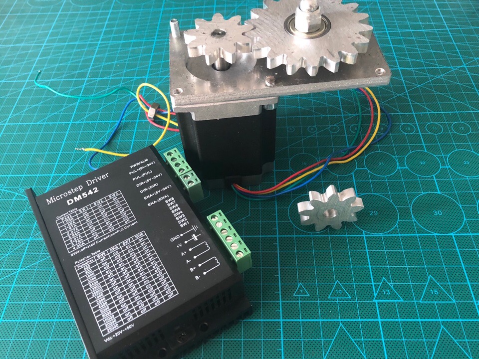
By the presence I had trimmed dural sheet 6mm thick. As a drive, I decided to use the Stepper Engine (SD) 23HS8430, I also had it in stock and was lying idle.
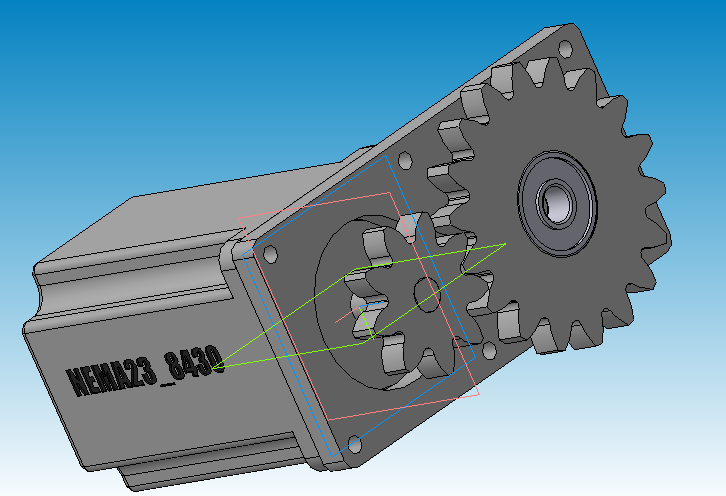
The design began with the simulation of the whole mechanism in Compass 3D, several restrictions immediately arose due to the small size of the duralumin billet, and this accordingly affected the dimensions of the driven gear, as well as the number and size of the teeth, since the smallest cutter diameter I had , was only 2mm, which means that the smallest radius of which I can describe the contour in the manufacturing process is 1mm.
Taking into account all the limitations, I turned the engine into a 3D model and then began to match the rest of the details with it ...
Now as for the construction of a gear pair: in the engineering configuration Compass 3D (v13) there is such a utility as “Calculations of a cylindrical gear transmission of external gearing”, in it we make a geometric calculation, entering the required parameters: the number of teeth, module, etc. I will not go deep into it, it will be enough to read the chapter about the construction of gears from the course of mechanics: machine parts.
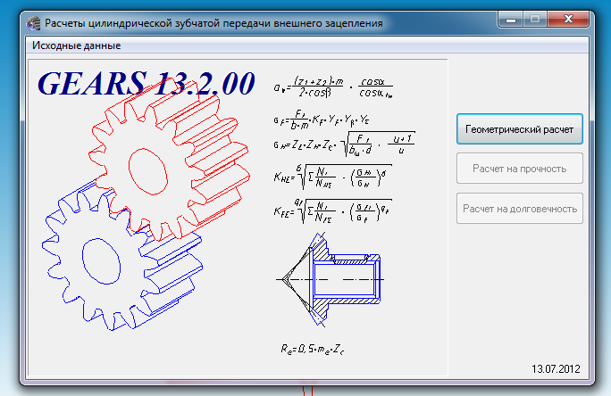
The utility used by me calculates and builds the gear, and if errors occur in the calculation, it informs about it. After calculation displays the report with all the geometric dimensions. From it, I only needed the center distance, since it draws the gear itself automatically.

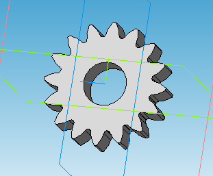
For more interest, I decided to make gears with different number of teeth and gear ratio 2: 1.
Based on the center distance, the base was drawn. With him mated the engine and axle, which will be mounted driven gear.
After the end of 3D design, all the details translated into a 2D view and saved them in vector format * .dxf.
In order to cut out all the details on the machine, I converted the vector format to G-code through a postprocessor in the ArtCam program. The resulting file is loaded into the machine and after zeroing the coordinates, cut out all the details.
The bearing was pressed into the driven gear, it entered tightly enough, since I had underestimated the hole by several hundred parts.
Separately, an axis was machined on a lathe, on which the driven gear is mounted.
Then everything is quite simple, assembled the knot in one, and it remains only to tighten it.
But I had to wait a month, as I did not have a driver for the SD, and I ordered the DM542 driver on Ali.
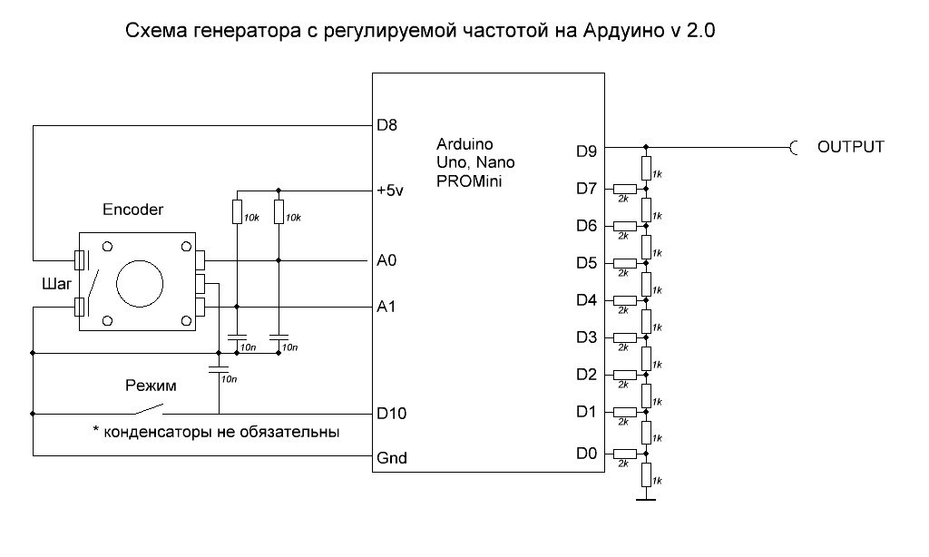
In order for the SM to spin into the driver input, it is necessary to send a frequency signal, for this I assembled a frequency generator with a variable frequency using an externally connected encoder for 24 pulses to Arduino Uno.
Just want to make a reservation that the code for firmware Arduino found on the Internet.
The frequency generator can: - generate a meander on a 16-bit timer. Frequency range 1Hz - 8MHz. Frequency adjustment is performed by the encoder. Up to a frequency of 2.8 kHz, a resolution of 1 Hz, at frequencies above the timer, the hardware can no longer support this resolution, therefore, higher frequencies are synthesized by setting the parameter not to the desired frequency, but simply increasing the comparison register. It turns out the higher the frequency - the greater the step between the encoder clicks. Rotating the encoder, with a button not pressed, the frequency changes to 1 Hz; with the button pressed one step - 100Hz. Above 2.8 kHz. rotating the encoder while pressing the button also speeds up the counting. There is no software suppression of the chattering of the encoder contacts, so it is necessary to hang up the capacitors 0.01.0.0.1 microfarads. relative to the earth. On the button, the capacitor is optional. Calculated mathematically frequency is displayed in the series.
Once everything is assembled, connected, and poured a sketch into the Arduino, you can proceed to the inclusion:
Now about the work of this mechanism: the rotation and the work of the transfer is not completely bad, even when the gears are ringing. As a result, it was possible to overclock the pinion gear to 12.5 revolutions per second, and the follower gear was two times smaller, respectively. The generated frequency was about 5 kHz at 400 pulses / rev. exposed on the driver. At this frequency, the engine has not yet gone into a stupor, which means that it was possible to give a frequency and more.
Thanks for reading! :)
Not so long ago, I designed a portal machine with CNC , about its development and construction on this resource is my previous article.
At once I want to say that this project serves only to gain experience in designing simple gear pairs and their manufacture for possible use in subsequent projects.
')
Since it was planned to process not only wood and plastics, but also duralumin on the manufactured machine, it was interesting to make a gear pair out of this material.
By the presence I had trimmed dural sheet 6mm thick. As a drive, I decided to use the Stepper Engine (SD) 23HS8430, I also had it in stock and was lying idle.
The design began with the simulation of the whole mechanism in Compass 3D, several restrictions immediately arose due to the small size of the duralumin billet, and this accordingly affected the dimensions of the driven gear, as well as the number and size of the teeth, since the smallest cutter diameter I had , was only 2mm, which means that the smallest radius of which I can describe the contour in the manufacturing process is 1mm.
Taking into account all the limitations, I turned the engine into a 3D model and then began to match the rest of the details with it ...
Now as for the construction of a gear pair: in the engineering configuration Compass 3D (v13) there is such a utility as “Calculations of a cylindrical gear transmission of external gearing”, in it we make a geometric calculation, entering the required parameters: the number of teeth, module, etc. I will not go deep into it, it will be enough to read the chapter about the construction of gears from the course of mechanics: machine parts.
The utility used by me calculates and builds the gear, and if errors occur in the calculation, it informs about it. After calculation displays the report with all the geometric dimensions. From it, I only needed the center distance, since it draws the gear itself automatically.
For more interest, I decided to make gears with different number of teeth and gear ratio 2: 1.
Based on the center distance, the base was drawn. With him mated the engine and axle, which will be mounted driven gear.
After the end of 3D design, all the details translated into a 2D view and saved them in vector format * .dxf.
In order to cut out all the details on the machine, I converted the vector format to G-code through a postprocessor in the ArtCam program. The resulting file is loaded into the machine and after zeroing the coordinates, cut out all the details.
The bearing was pressed into the driven gear, it entered tightly enough, since I had underestimated the hole by several hundred parts.
Separately, an axis was machined on a lathe, on which the driven gear is mounted.
Then everything is quite simple, assembled the knot in one, and it remains only to tighten it.
But I had to wait a month, as I did not have a driver for the SD, and I ordered the DM542 driver on Ali.
In order for the SM to spin into the driver input, it is necessary to send a frequency signal, for this I assembled a frequency generator with a variable frequency using an externally connected encoder for 24 pulses to Arduino Uno.
Just want to make a reservation that the code for firmware Arduino found on the Internet.
The frequency generator can: - generate a meander on a 16-bit timer. Frequency range 1Hz - 8MHz. Frequency adjustment is performed by the encoder. Up to a frequency of 2.8 kHz, a resolution of 1 Hz, at frequencies above the timer, the hardware can no longer support this resolution, therefore, higher frequencies are synthesized by setting the parameter not to the desired frequency, but simply increasing the comparison register. It turns out the higher the frequency - the greater the step between the encoder clicks. Rotating the encoder, with a button not pressed, the frequency changes to 1 Hz; with the button pressed one step - 100Hz. Above 2.8 kHz. rotating the encoder while pressing the button also speeds up the counting. There is no software suppression of the chattering of the encoder contacts, so it is necessary to hang up the capacitors 0.01.0.0.1 microfarads. relative to the earth. On the button, the capacitor is optional. Calculated mathematically frequency is displayed in the series.
/* 1 Hz..8 MHz. A0 A1, A2. 0,01..0,1uf 2 . atmega328 (UNO,Nano, MiniPro) */ float freq; void setup() { pinMode (9,OUTPUT); // pinMode(A0,INPUT); // , - pinMode(A1,INPUT); // - . , . pinMode(A2,INPUT_PULLUP); // Serial.begin(9600); PCICR=1<<PCIE1; // PCINT PCMSK1=(1<<PCINT9);// 1 TCCR1A=1<<COM1A0; // OC1A TCCR1B=0;// } ISR (PCINT1_vect){ static boolean gen_mode=0; // static uint32_t enc=1; // uint32_t ocr=OCR1A; uint32_t divider=1; // . byte n=PINC&3; // boolean knopka = PINC&(1<<2); // 0- , 1- . if (freq<2848) gen_mode=0; // if (freq>=2848) gen_mode=1; // OCR // if (n==3||n==0){ if (gen_mode){if (knopka){ if(ocr>0) {ocr--; } } else { if(ocr>9)ocr-=10; } } else knopka? enc++ : enc+=100; // } //end GetUP // if (n==2||n==1){ if (gen_mode){ if (knopka){ if(ocr<65535) {ocr++; } } else { if(ocr<=65525)ocr+=10; } } else {if (knopka) { if (enc>=2)enc--; } else { if (enc>100) enc-=100; } } } //end GetDown if(gen_mode){ OCR1A=ocr; freq= (float)F_CPU/2 / (OCR1A+1); } else { // OCR divider=1; ocr = (F_CPU / enc /2 /divider) -1; if (ocr >65536) { divider=8; ocr = F_CPU / enc /2 /divider; if (ocr >65536) { divider=64; ocr = F_CPU / enc /2 /divider; if (ocr >65536) {divider=256; ocr = F_CPU / enc /2 /divider; if (ocr >65536) { divider=1024; ocr = F_CPU / enc /2 /divider; if (ocr >65536){ocr=65536; }}}}} OCR1A=ocr-1; // switch (divider) { case 1: TCCR1B=1|(1<<WGM12); break; case 8: TCCR1B=2|(1<<WGM12); break; case 64: TCCR1B=3|(1<<WGM12); break; case 256: TCCR1B=4|(1<<WGM12); break; case 1024: TCCR1B=5|(1<<WGM12); break; } freq= (float) F_CPU/2 / (OCR1A+1) /divider; } //end if !gen_mode } void loop() { if (freq <10000) { Serial.print(freq,1);Serial.println(" Hz "); } if (freq >10000) { Serial.print(freq/1000,3);Serial.println(" kHz");} delay(100); } Once everything is assembled, connected, and poured a sketch into the Arduino, you can proceed to the inclusion:
Now about the work of this mechanism: the rotation and the work of the transfer is not completely bad, even when the gears are ringing. As a result, it was possible to overclock the pinion gear to 12.5 revolutions per second, and the follower gear was two times smaller, respectively. The generated frequency was about 5 kHz at 400 pulses / rev. exposed on the driver. At this frequency, the engine has not yet gone into a stupor, which means that it was possible to give a frequency and more.
Thanks for reading! :)
Source: https://habr.com/ru/post/424273/
All Articles