Applications or what is missing load balancers
A couple of years ago, I completed a migration project on the network of one of our clients, the task was to change the platform that distributes the load between servers. The scheme of providing services to this client has evolved over the course of almost 10 years with new developments in the data center industry, so the “picky” customer, in a good sense of the word, expected a solution that would satisfy not only the requirements of network equipment, load balancers and servers , but also would possess such properties as scalability, flexibility, mobility and simplicity. In this article, I will try to consistently, from simple to complex, set forth the main examples of using load balancers without reference to the manufacturer, their features and methods of interfacing with the data transfer network.
Load balancers are now increasingly called Application Delivery Controllers (ADCs). But if applications are running on the server, why should they be delivered somewhere? For reasons of fault tolerance or scaling, an application can be running on more than one server, in which case a kind of reverse proxy server is needed, which will hide internal complexity from consumers, select the correct server, deliver the request to it and ensure that the server returns the correct , from the point of view of the protocol, the result; otherwise, it will select another server and send a request there. To implement these functions, the ADC must understand the semantics of the application-level protocol it works with, it allows you to customize the appication specific rules for traffic delivery, analyzing the result and checking the server status. For example, understanding the semantics of HTTP makes configuration possible when HTTP requests
sent to one server group with subsequent compression of results and caching, and requests
processed by completely different rules.
')
Understanding the semantics of the protocol allows you to organize session-level objects of the application protocol, for example, using HTTP Headers, RDP Cookie, or multiplexing requests to fill a single transport session with many user requests if the application layer of the protocol allows you to do this.
The scope of use of ADC is sometimes unnecessarily imagined only by HTTP traffic, in fact, the list of supported protocols for most manufacturers is much broader. Even working without understanding the semantics of the application layer protocol, the ADC can be useful for solving various tasks, for example, I took part in building a self-sufficient virtual farm of SMTP servers; during spam attacks, the number of instances is increased by using feedback control along the length of the message queue to provide a satisfactory time for checking messages with resource-intensive algorithms. During activation, the server was registered on the ADC and received its portion of new TCP sessions. In the case of SMTP, this scheme of work was fully justified due to the high entropy of connections at the network and transport levels; to distribute the load evenly during ADC spam attacks, only TCP support is required. A similar scheme can be used to build a farm of database servers, high-load DNS, DHCP, AAA or Remote access servers, when servers can be considered equivalent in the subject domain and when their performance characteristics are not too different from each other. I will not go deeper into the topic of protocol features, this aspect is too broad to present it in the introduction, if something seems interesting - write, perhaps this is the reason for an article with a deeper presentation of some application, and now we’ll get to the point.
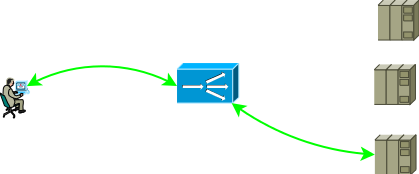
Most often, the ADC closes the transport layer, so the end-to-end TCP session between the consumer and the server becomes composite, the consumer establishes the session with the ADC, and the ADC with one of the servers.
Pic1
The network configuration and addressing settings should ensure such traffic advancement so that the two parts of the TCP session go through the ADC. The easiest way to get the traffic of the first part to come to the ADC is to assign one of the ADC interface addresses to the service address, with the second part the following options are possible:
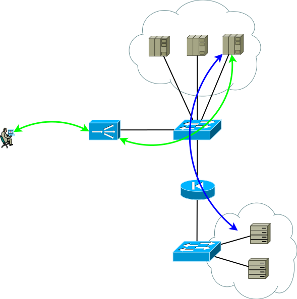
In fact, a slightly more realistic view of the first application scheme already looks like this, this is the basis from which we begin:
Pic2
The second group of servers can be databases, back-end applications, network storages or front-end for another set of services in the case of decomposition of a classic application into micro services. This server group can be a separate routing domain, with its own policies, located in another data center, or even be isolated for security reasons. Servers are rarely located in the same segment, more often they are placed into segments for functional purposes with clearly regulated access policies, in the figure this is depicted as a firewall.
Studies show that modern multi-tier applications generate more West-East traffic, and you probably don’t want all intra-coding / inter-segment traffic to go through ADC. The switches in Figure 2 are not necessarily physical - routing domains can be implemented using virtual entities, which are called virtual-router, vrf, vr, vpn-instance or virtual routing table for different manufacturers.
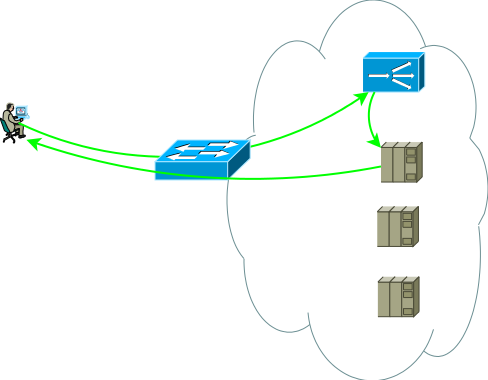
By the way, there is also a variant of interfacing with the network, without the requirement for symmetry of traffic flows from the consumer to the ADC and from the ADC to the servers, it is in demand in cases of long-living sessions, through which a very large amount of traffic is transmitted in one direction, for example, streaming or broadcast video content. In this case, the ADC sees only the stream from the client to the servers, this stream is delivered to the ADC interface address and after simple processing, which consists in replacing the MAC address with the interface MAC of one of the servers, the request is sent to the server where the service address is assigned to one of the logical interfaces. The reverse traffic from the server to the consumer goes, bypassing the ADC in accordance with the server's routing table. Supporting a single broadcast domain for all front-ends can be very difficult, besides, the ADC’s ability to analyze responses and support sessionality is very limited in this case, in fact, it’s just a switch, so this option isn’t considered further, although in a solution to some narrow ones tasks can be used.
Pic.3
So, we have one basis-DPC, shown in Figure 2, let's think about what problems can push the basis-DPC to evolution, I see two topics for analysis:
These tasks are similar to the fact that, in the process of solving them, the number of ADC instances should definitely increase. At the same time, fault tolerance can be organized according to the scheme Active / Backup and Active / Active, and scaling only according to the scheme Active / Active. Let's try to solve them individually and see what properties different solutions have.
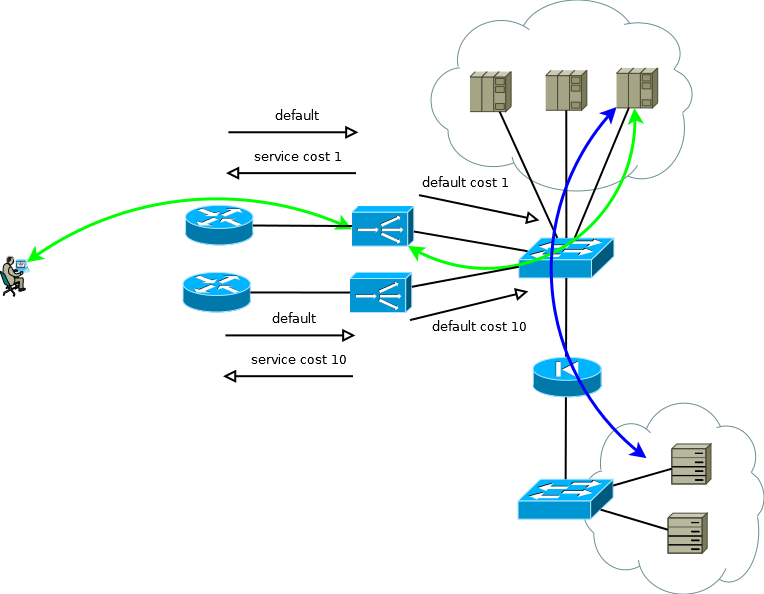
Many manufacturers' ADCs can be considered as elements of the network infrastructure, RIP, OSPF, BGP - all this is there, which means you can build a trivial Active / Backup backup scheme. The active ADC sends the service prefixes to the upstream router, and takes the default route from it to fill in its table and to transfer to the data center in the appropriate virtual routing table. The backup ADC does the same thing, but using the semantics of the selected routing protocol, forms less attractive announcements. Servers with this approach can see the real IP address of the consumer, since there is no reason to use address translation. This scheme also works elegantly if there is more than one upstream router, but to avoid a situation where the active ADC loses default and connectivity with the router, it still receives default from the backup ADC and continues to announce it in the direction of the data center, try to avoid the proximity between ADC and the use of static routes.
Pic.4
If the servers do not have to operate with the real IP addresses of the consumer, or the application layer protocol allows embedding it in headers, such as HTTP, the scheme turns into Active / Active with an almost linear dependence of performance on the number of ADCs. In the case of more than one upstream router, care must be taken that incoming traffic comes in more or less uniform chunks. This task is easy to solve if in the ECMP routing domain the transfer begins before these routers, if it is difficult or if the routing domain is not serviced by you - you can use full-mesh connections between the ADX and the routers so that the ECMP transfer starts directly on them.

Pic.5
At the beginning of this part, I wrote that resiliency and scaling are two big differences. Solutions to these problems have different levels of resource utilization, if you design an Active / Standby scheme, you need to accept the fact that half of the resources will be idle. And if it so happens that you need to take the next quantitative step, be prepared in the future to multiply the required resources by another two.
The advantages of Active / Active begin to manifest when you operate with a large number of devices by two. Suppose you need to ensure the performance of 8 standard units (8 thousand connections per second, or 8 million simultaneous sessions) and provide a scenario of failure of one device, in Active / Active variant you only need three copies of ADC with a capacity of 4, in the case of Active / Standby - two to 8. If you translate these numbers into resources that are idle, it turns out one-third to half. The same calculation principle can be used to estimate the proportion of broken connections in the period of partial failure. With the increase in the number of Active / Active instances, mathematics becomes even more pleasant, and the system gets the possibility of a smooth increase in performance instead of stepwise Active / Standby.
It would be correct to mention another method Active / Active or Active / Standby work schemes - clustering. But it will not be very correct to devote a lot of time to this, since I tried to write about approaches, and not about the features of manufacturers. When choosing such a solution, you need to clearly understand the following things:
Nevertheless, there are positive things:
So, our data center from Figure 5 continues to grow; the task that you may have to solve is to increase the number of servers. It is not always possible to do this in the existing data center, so suppose that a new spacious location with additional servers has appeared.

Pic.6
The new site may not be very far away, then you successfully solve the problem by extending the routing domains. A more general case, which does not exclude the appearance of a site in another city or in another country, will pose a new problem for the data center:
Maintaining a wide channel between sites can be very costly, and choosing the location will no longer be a trivial task — an overloaded site with a short response time or a free one with a large one. Thinking about this will push you to build a geographically distributed data center configuration. This configuration, on the one hand, is user-friendly, as it allows you to receive service at a point close to yourself, on the other hand, it can significantly reduce the requirements for the channel strip between sites.
For the case when real IP addresses do not have to be accessible to servers, or when the application-level protocol allows them to be transmitted in headers, the device of a geographically distributed data center is not much different from what I called the basis-data center. An ADC at any site may send requests for processing to local servers or send them for processing to a neighboring server, the broadcast of the consumer’s address makes this possible. Some attention needs to be paid to monitoring the volume of incoming traffic in order to maintain the number of ADCs within the site with an adequate share of the traffic that the site receives. Broadcasting a consumer address allows you to increase / decrease the number of ADCs or even move instances between sites in accordance with changes in the incoming traffic matrix, or during migration / launch. Despite the simplicity, the scheme is quite flexible, has a pleasant performance characteristics and is easily replicated on the number of sites greater than two.

Fig.7
If you are working with a protocol that allows you to send requests, as in the case of HTTP Redirect, this feature can be used as an additional lever to control the load of the channel between sites, as a mechanism for performing routine work on servers or as a method of building Active / Backup server farms on different sites. At the required point in time, automatically or after some events triggers, ADC can take traffic from local servers and move consumers to the next site. It is worthwhile to pay close attention to the development of this algorithm so that the coordinated work of the ADC excludes the possibility of mutual sending requests or resonances.
Of particular interest is the case when servers need real IP addresses of consumers, and the application layer protocol does not have the ability to transfer additional headers, or when ADCs work without understanding the semantics of the application layer protocol. In this case, it is impossible to ensure a consistent connection of TCP session segments simply by declaring a route to ADC default. If you do this, the servers of the first site will start using the local ADC as the default gateway for sessions that came from the second site, the TCP session itself will not be established in this case because the ADC of the first site will see only one side of the session.
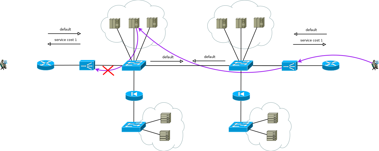
Fig.8
There is a little trick that still allows you to run Active / Active ADC in combination with Active / Active server farms at different sites (I don’t consider Active / Backup at two sites; careful reading of the above will allow you to solve this problem without further discussion). The trick is to use on the second site ADC not the interface addresses of the servers, but the logical address of the ADC that corresponds to the server farm on the first site. Servers at the same time accept traffic as if it came from the local ADC and use the local default gateway. To maintain this mode of operation on the ADC, it is necessary to activate the function of remembering the interface from which the first packet came to install the TCP session. Different manufacturers call this function differently, but the essence is the same - to remember the interface in the session state table and use it for return traffic without paying attention to the routing table. The scheme is quite workable and allows you to flexibly distribute the load across all available servers wherever they are. In the case of two or more sites, the failure of one ADC does not affect the availability of the service as a whole, but completely excludes the possibility of processing traffic on the servers of the site with the failed ADC, this should be remembered when predicting behavior and load during partial failures.
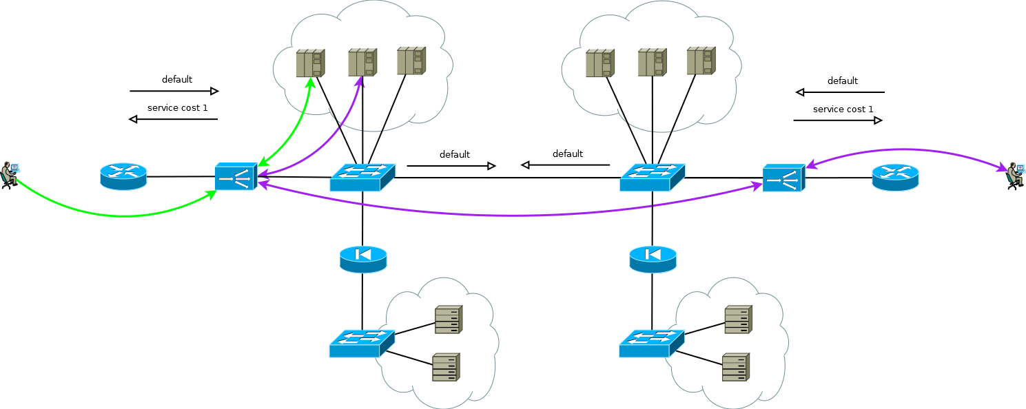
Fig.9
Approximately according to this scheme, the services of our client functioned, when I took up work in the project of migration to the new ADC platform. There was no great difficulty in simply recreating the behavior of the devices of the old platform on a new one within the framework of a proven and satisfactory scheme for the client, this was what was expected of us.
But look again at Figure 9, do you see there what can be optimized?
The main disadvantage of working with the ADC chain is that the processing of some part of the sessions consumes the resources of two ADCs. In the case of this client, the choice was absolutely conscious, it was due to the specifics of the applications and the need to be able to very quickly (from 20 to 50 seconds) redistribute the load between servers of different sites. At different times, double processing took an average of 15 to 30 percent of ADC resources, which is enough to think about optimization. Having discussed this point with the client's engineers, we suggested replacing the support of the ADC session table with binding to the interface by routing the source on the servers using PBR on the Linux IP IP stack. As a key, we considered such options as:
The first and second options somehow would have an impact on the network as a whole. Among the side effects of option number one, we found an unacceptable increase in multiple to the number of ADC, ARP tables on the switches, and the second option would require an increase in the number of pass-through broadcast domains between sites or individual instances of virtual routing tables. The local nature of the third option seemed very attractive to us, and we set to work, which resulted in a simple controller that automates the configuration of tunnels on servers and ADC, as well as the configuration of PBR on the IP stack of Linux servers.

Pic.10
As I wrote the migration was completed, the client got what he wanted - a new platform, simplicity, flexibility, scalability, and, as a result of the transition to the overlay, simplified network equipment configuration as part of servicing these services - instead of several instances of virtual tables and large broadcast domains, something like a simple IP factory.
, ADC, . , , . -, ADC , , « ».
, PULL PUSH . , application specific . , , BGP Cost Community, .
ADC , PUSH -. , , ADC - BGP Flow-Spec.
. … , , . - , , , . . , , , SDN . , , .
Load balancers are now increasingly called Application Delivery Controllers (ADCs). But if applications are running on the server, why should they be delivered somewhere? For reasons of fault tolerance or scaling, an application can be running on more than one server, in which case a kind of reverse proxy server is needed, which will hide internal complexity from consumers, select the correct server, deliver the request to it and ensure that the server returns the correct , from the point of view of the protocol, the result; otherwise, it will select another server and send a request there. To implement these functions, the ADC must understand the semantics of the application-level protocol it works with, it allows you to customize the appication specific rules for traffic delivery, analyzing the result and checking the server status. For example, understanding the semantics of HTTP makes configuration possible when HTTP requests
GET /docs/index.html HTTP/1.1 Host: www.company.com Accept-Language: en-us Accept-Encoding: gzip, deflate sent to one server group with subsequent compression of results and caching, and requests
POST /api/object-put HTTP/1.1 HOST: b2b.company.com X-Auth: 76GDjgtgdfsugs893Hhdjfpsj Content-Type: application/json processed by completely different rules.
')
Understanding the semantics of the protocol allows you to organize session-level objects of the application protocol, for example, using HTTP Headers, RDP Cookie, or multiplexing requests to fill a single transport session with many user requests if the application layer of the protocol allows you to do this.
The scope of use of ADC is sometimes unnecessarily imagined only by HTTP traffic, in fact, the list of supported protocols for most manufacturers is much broader. Even working without understanding the semantics of the application layer protocol, the ADC can be useful for solving various tasks, for example, I took part in building a self-sufficient virtual farm of SMTP servers; during spam attacks, the number of instances is increased by using feedback control along the length of the message queue to provide a satisfactory time for checking messages with resource-intensive algorithms. During activation, the server was registered on the ADC and received its portion of new TCP sessions. In the case of SMTP, this scheme of work was fully justified due to the high entropy of connections at the network and transport levels; to distribute the load evenly during ADC spam attacks, only TCP support is required. A similar scheme can be used to build a farm of database servers, high-load DNS, DHCP, AAA or Remote access servers, when servers can be considered equivalent in the subject domain and when their performance characteristics are not too different from each other. I will not go deeper into the topic of protocol features, this aspect is too broad to present it in the introduction, if something seems interesting - write, perhaps this is the reason for an article with a deeper presentation of some application, and now we’ll get to the point.
Most often, the ADC closes the transport layer, so the end-to-end TCP session between the consumer and the server becomes composite, the consumer establishes the session with the ADC, and the ADC with one of the servers.
Pic1
The network configuration and addressing settings should ensure such traffic advancement so that the two parts of the TCP session go through the ADC. The easiest way to get the traffic of the first part to come to the ADC is to assign one of the ADC interface addresses to the service address, with the second part the following options are possible:
- ADC as default gateway for server network;
- broadcast on ADC consumer addresses in one of their interface addresses.
In fact, a slightly more realistic view of the first application scheme already looks like this, this is the basis from which we begin:
Pic2
The second group of servers can be databases, back-end applications, network storages or front-end for another set of services in the case of decomposition of a classic application into micro services. This server group can be a separate routing domain, with its own policies, located in another data center, or even be isolated for security reasons. Servers are rarely located in the same segment, more often they are placed into segments for functional purposes with clearly regulated access policies, in the figure this is depicted as a firewall.
Studies show that modern multi-tier applications generate more West-East traffic, and you probably don’t want all intra-coding / inter-segment traffic to go through ADC. The switches in Figure 2 are not necessarily physical - routing domains can be implemented using virtual entities, which are called virtual-router, vrf, vr, vpn-instance or virtual routing table for different manufacturers.
By the way, there is also a variant of interfacing with the network, without the requirement for symmetry of traffic flows from the consumer to the ADC and from the ADC to the servers, it is in demand in cases of long-living sessions, through which a very large amount of traffic is transmitted in one direction, for example, streaming or broadcast video content. In this case, the ADC sees only the stream from the client to the servers, this stream is delivered to the ADC interface address and after simple processing, which consists in replacing the MAC address with the interface MAC of one of the servers, the request is sent to the server where the service address is assigned to one of the logical interfaces. The reverse traffic from the server to the consumer goes, bypassing the ADC in accordance with the server's routing table. Supporting a single broadcast domain for all front-ends can be very difficult, besides, the ADC’s ability to analyze responses and support sessionality is very limited in this case, in fact, it’s just a switch, so this option isn’t considered further, although in a solution to some narrow ones tasks can be used.
Pic.3
So, we have one basis-DPC, shown in Figure 2, let's think about what problems can push the basis-DPC to evolution, I see two topics for analysis:
- Suppose that the switching subsystem is fully reserved, let's not worry about how and with what, the topic is too extensive. Applications run on multiple servers and are backed up using ADC, but how to reserve the ADC itself?
- If the analysis shows that the next seasonal peak load may exceed the capabilities of the ADC, you, of course, will think about scalability.
These tasks are similar to the fact that, in the process of solving them, the number of ADC instances should definitely increase. At the same time, fault tolerance can be organized according to the scheme Active / Backup and Active / Active, and scaling only according to the scheme Active / Active. Let's try to solve them individually and see what properties different solutions have.
Many manufacturers' ADCs can be considered as elements of the network infrastructure, RIP, OSPF, BGP - all this is there, which means you can build a trivial Active / Backup backup scheme. The active ADC sends the service prefixes to the upstream router, and takes the default route from it to fill in its table and to transfer to the data center in the appropriate virtual routing table. The backup ADC does the same thing, but using the semantics of the selected routing protocol, forms less attractive announcements. Servers with this approach can see the real IP address of the consumer, since there is no reason to use address translation. This scheme also works elegantly if there is more than one upstream router, but to avoid a situation where the active ADC loses default and connectivity with the router, it still receives default from the backup ADC and continues to announce it in the direction of the data center, try to avoid the proximity between ADC and the use of static routes.
Pic.4
If the servers do not have to operate with the real IP addresses of the consumer, or the application layer protocol allows embedding it in headers, such as HTTP, the scheme turns into Active / Active with an almost linear dependence of performance on the number of ADCs. In the case of more than one upstream router, care must be taken that incoming traffic comes in more or less uniform chunks. This task is easy to solve if in the ECMP routing domain the transfer begins before these routers, if it is difficult or if the routing domain is not serviced by you - you can use full-mesh connections between the ADX and the routers so that the ECMP transfer starts directly on them.
Pic.5
At the beginning of this part, I wrote that resiliency and scaling are two big differences. Solutions to these problems have different levels of resource utilization, if you design an Active / Standby scheme, you need to accept the fact that half of the resources will be idle. And if it so happens that you need to take the next quantitative step, be prepared in the future to multiply the required resources by another two.
The advantages of Active / Active begin to manifest when you operate with a large number of devices by two. Suppose you need to ensure the performance of 8 standard units (8 thousand connections per second, or 8 million simultaneous sessions) and provide a scenario of failure of one device, in Active / Active variant you only need three copies of ADC with a capacity of 4, in the case of Active / Standby - two to 8. If you translate these numbers into resources that are idle, it turns out one-third to half. The same calculation principle can be used to estimate the proportion of broken connections in the period of partial failure. With the increase in the number of Active / Active instances, mathematics becomes even more pleasant, and the system gets the possibility of a smooth increase in performance instead of stepwise Active / Standby.
It would be correct to mention another method Active / Active or Active / Standby work schemes - clustering. But it will not be very correct to devote a lot of time to this, since I tried to write about approaches, and not about the features of manufacturers. When choosing such a solution, you need to clearly understand the following things:
- Cluster architecture sometimes imposes restrictions on this or that functionality, in some projects it is important, in some it can become fundamentally in the future, everything depends strongly on the manufacturer and each solution needs to be worked out individually;
- A cluster is often one fault domain, there will be errors in the software.
- A cluster is easy to assemble, but very difficult to disassemble. Technology has less mobility - you cannot control parts of the system.
- You get into the tenacious embrace of his manufacturer.
Nevertheless, there are positive things:
- The cluster is easy to install and easy to use.
- Sometimes you can expect near-optimal resource utilization.
So, our data center from Figure 5 continues to grow; the task that you may have to solve is to increase the number of servers. It is not always possible to do this in the existing data center, so suppose that a new spacious location with additional servers has appeared.
Pic.6
The new site may not be very far away, then you successfully solve the problem by extending the routing domains. A more general case, which does not exclude the appearance of a site in another city or in another country, will pose a new problem for the data center:
- Disposal of canals between sites;
- The difference in processing time for requests that ADC has sent to close and distant servers.
Maintaining a wide channel between sites can be very costly, and choosing the location will no longer be a trivial task — an overloaded site with a short response time or a free one with a large one. Thinking about this will push you to build a geographically distributed data center configuration. This configuration, on the one hand, is user-friendly, as it allows you to receive service at a point close to yourself, on the other hand, it can significantly reduce the requirements for the channel strip between sites.
For the case when real IP addresses do not have to be accessible to servers, or when the application-level protocol allows them to be transmitted in headers, the device of a geographically distributed data center is not much different from what I called the basis-data center. An ADC at any site may send requests for processing to local servers or send them for processing to a neighboring server, the broadcast of the consumer’s address makes this possible. Some attention needs to be paid to monitoring the volume of incoming traffic in order to maintain the number of ADCs within the site with an adequate share of the traffic that the site receives. Broadcasting a consumer address allows you to increase / decrease the number of ADCs or even move instances between sites in accordance with changes in the incoming traffic matrix, or during migration / launch. Despite the simplicity, the scheme is quite flexible, has a pleasant performance characteristics and is easily replicated on the number of sites greater than two.
Fig.7
If you are working with a protocol that allows you to send requests, as in the case of HTTP Redirect, this feature can be used as an additional lever to control the load of the channel between sites, as a mechanism for performing routine work on servers or as a method of building Active / Backup server farms on different sites. At the required point in time, automatically or after some events triggers, ADC can take traffic from local servers and move consumers to the next site. It is worthwhile to pay close attention to the development of this algorithm so that the coordinated work of the ADC excludes the possibility of mutual sending requests or resonances.
Of particular interest is the case when servers need real IP addresses of consumers, and the application layer protocol does not have the ability to transfer additional headers, or when ADCs work without understanding the semantics of the application layer protocol. In this case, it is impossible to ensure a consistent connection of TCP session segments simply by declaring a route to ADC default. If you do this, the servers of the first site will start using the local ADC as the default gateway for sessions that came from the second site, the TCP session itself will not be established in this case because the ADC of the first site will see only one side of the session.
Fig.8
There is a little trick that still allows you to run Active / Active ADC in combination with Active / Active server farms at different sites (I don’t consider Active / Backup at two sites; careful reading of the above will allow you to solve this problem without further discussion). The trick is to use on the second site ADC not the interface addresses of the servers, but the logical address of the ADC that corresponds to the server farm on the first site. Servers at the same time accept traffic as if it came from the local ADC and use the local default gateway. To maintain this mode of operation on the ADC, it is necessary to activate the function of remembering the interface from which the first packet came to install the TCP session. Different manufacturers call this function differently, but the essence is the same - to remember the interface in the session state table and use it for return traffic without paying attention to the routing table. The scheme is quite workable and allows you to flexibly distribute the load across all available servers wherever they are. In the case of two or more sites, the failure of one ADC does not affect the availability of the service as a whole, but completely excludes the possibility of processing traffic on the servers of the site with the failed ADC, this should be remembered when predicting behavior and load during partial failures.
Fig.9
Approximately according to this scheme, the services of our client functioned, when I took up work in the project of migration to the new ADC platform. There was no great difficulty in simply recreating the behavior of the devices of the old platform on a new one within the framework of a proven and satisfactory scheme for the client, this was what was expected of us.
But look again at Figure 9, do you see there what can be optimized?
The main disadvantage of working with the ADC chain is that the processing of some part of the sessions consumes the resources of two ADCs. In the case of this client, the choice was absolutely conscious, it was due to the specifics of the applications and the need to be able to very quickly (from 20 to 50 seconds) redistribute the load between servers of different sites. At different times, double processing took an average of 15 to 30 percent of ADC resources, which is enough to think about optimization. Having discussed this point with the client's engineers, we suggested replacing the support of the ADC session table with binding to the interface by routing the source on the servers using PBR on the Linux IP IP stack. As a key, we considered such options as:
- additional IP address on servers on a common interface for each ADC;
- interface IP address on servers on a separate 802.1q for each ADC;
- separate overlay tunnel network on servers for each ADC.
The first and second options somehow would have an impact on the network as a whole. Among the side effects of option number one, we found an unacceptable increase in multiple to the number of ADC, ARP tables on the switches, and the second option would require an increase in the number of pass-through broadcast domains between sites or individual instances of virtual routing tables. The local nature of the third option seemed very attractive to us, and we set to work, which resulted in a simple controller that automates the configuration of tunnels on servers and ADC, as well as the configuration of PBR on the IP stack of Linux servers.
Pic.10
As I wrote the migration was completed, the client got what he wanted - a new platform, simplicity, flexibility, scalability, and, as a result of the transition to the overlay, simplified network equipment configuration as part of servicing these services - instead of several instances of virtual tables and large broadcast domains, something like a simple IP factory.
, ADC, . , , . -, ADC , , « ».
, PULL PUSH . , application specific . , , BGP Cost Community, .
ADC , PUSH -. , , ADC - BGP Flow-Spec.
. … , , . - , , , . . , , , SDN . , , .
Source: https://habr.com/ru/post/424115/
All Articles