The machine on the Arduino, controlled by an Android device via Bluetooth, is a full cycle (part 1)
Introduction
A detailed history of how the Arduino car was assembled from three engines, controlled by an Android device via Bluetooth. In several dozens of paragraphs I will try to state in the most step-by-step way where to connect each of the wires, how to write a company application and on which children’s rakes I had to jump more than a week.
A little about the level, the author and cautions
I, the author, a boy of 16-17 years old from a village in the Moscow region, specialize in writing android applications (and it’s harder to burn something there), so I’m not taking responsibility for the optimal approach to solving problems.
Practically each of the stages described below took more than my time. Probably for this reason I want to share my experience. And at the same time I will be very happy if you scold for errors and prompt for optimization.
')
Task
The easiest task is to make the car driven by the Arduino drive, and replace the console with android. But in most moments I had to reinvent the wheel, because no suitable solution was found on the Internet.
Will need
- Arduino
- Motor Shield (in my case two)
- Bluetooth
- Android
- Ordinary wires
Basis of construction
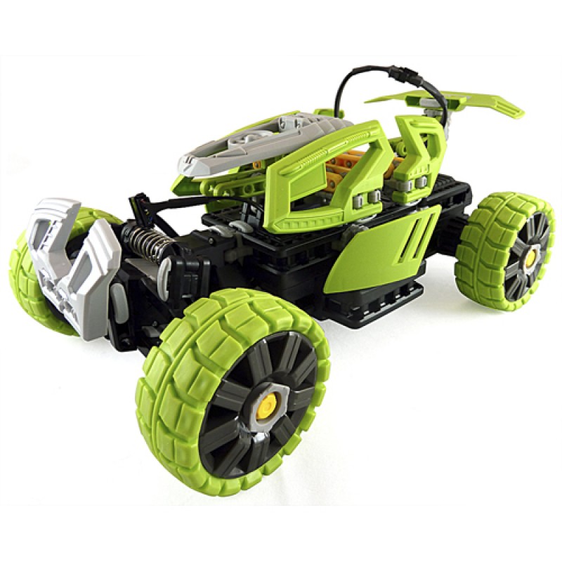
The basis was taken machine Lego Outdoor Challenger (in reality, it looks less pretentious). All that remains of it: the case (all the decorations were removed) and three engines.
The machine had its own board, but one of the tasks meant universality: I did it, others can repeat it. Brains pulled out, put the Arduino Uno.
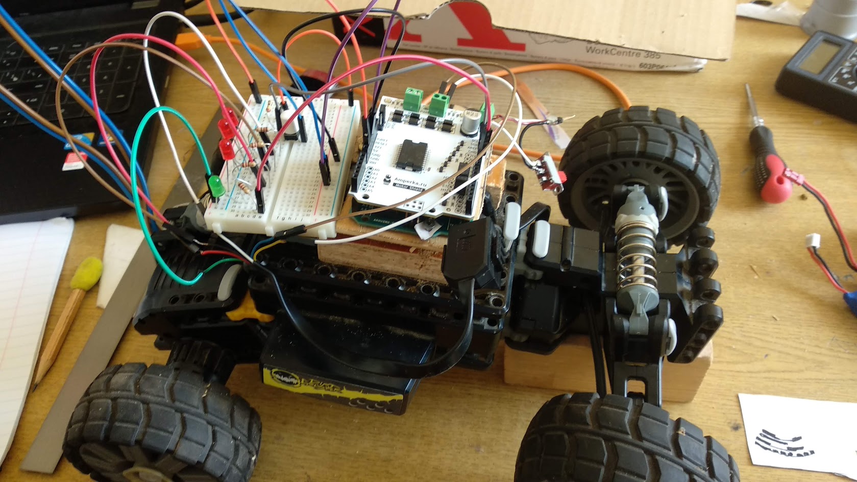
Install arduino
For some reason, the creators did not provide a place for the Arduino, so they fastened it onto the screws by drilling plastic. Plywood is planted under the board so that nothing is short-circuited. It is better to slip something plastic under the screws (a piece of the bottle), because the board is not protected from iron bolts.

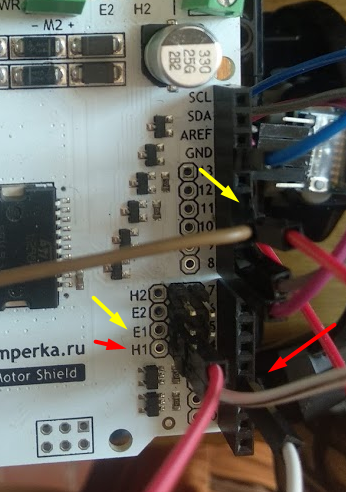
Immediately put two motor shiled on top of the board, that's right. To control the second one, you have to push one wire from any digital port to H1 (direction) and the second one from pin with shima support (marked with “~”, usually 10, 11) to E1 (speed).
Determination of the angle of rotation
For turning the machine is responsible, surprisingly, not the servo, but the usual engine. There is a problem: it would be good not to burn it, because the angle of rotation is limited, and the engine can spin as much as you like.
The option with a spear method disappears, since with a different battery level the amount of current supplied to the motor will vary, which will lead to a constantly changing angle. It is impossible to twist all the way too, sooner or later the gears will scatter.
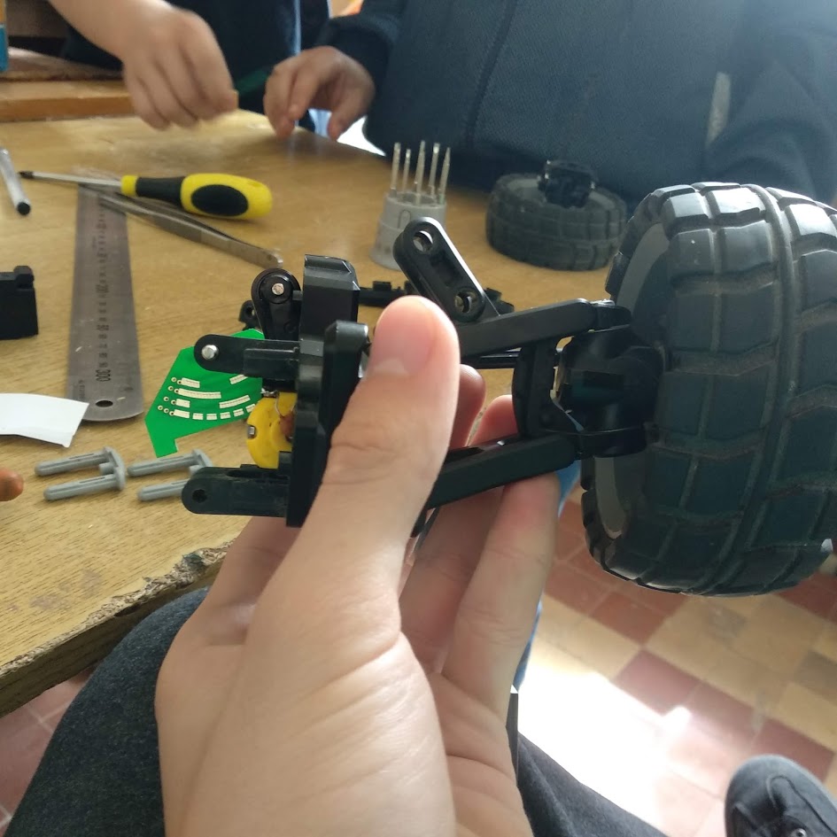
Solution of the problem: track the angle through the closure. The photo shows a small thing, which is mounted near the turning mechanism. On the part that turns with the wheels to the left / right of the engine, the comb with iron contacts is attached.
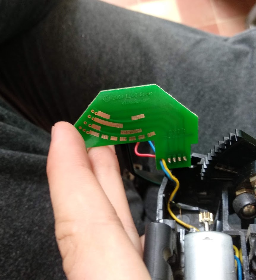
Principle of operation: a wire is soldered to each line (there are four of them), the lower one is connected to the positive (it is always clamped with a comb, see the picture), the other wires go to minus. When the tooth of the scallop hits both the bottom row and, say, the third, a short circuit occurs, the current flows, the Arduino notices.

Thanks to the different combinations of the three bands, you can define up to seven corners. For example, when there is current on all lines, the wheels are turned to the extreme right position, when there is only current on the top, the wheels are turned to the maximum left. The table provides all the options.

Connect angle and code
A color was chosen for each level: the bottom one was green, the first one was red, the second one was black, and the third one was white. At the initial stage, breadboard and LEDs for visual debugging were used.
The wiring diagram is shown in the figure. Plus we pull to the green, stretch the rest to the minus. Through a resistor installed to eliminate noise and the absence of short-circuit, connect the wires to the outputs A0-A2. They are simply selected from the savings of other ports.
The code is given with comments. Connect pins and poll them via digitarRead (). If voltage is present, true will be returned. Next, we look if the result means that the wheels are in extreme positions, prohibiting further rotation in this direction.
A little trick: since the outputs for 5V and 3.3V will be needed in the future, you can put a plus on one of the digital pins. Before each angle check, issue a current through digitalWrite (whitePin), then check the angle and remove the current.
int speedTurn = 180; // , 0 255 // int pinRed = A0; int pinWhite = A1; int pinBlack = A2; int pinAngleStop = 12; // , , // void setup() { // pinMode(pinRed, INPUT); pinMode(pinBlack, INPUT); pinMode(pinWhite, INPUT); // pinMode(pinAngleStop, OUTPUT); // , pinMode(angleDirection, OUTPUT); pinMode(angleSpeed, OUTPUT); Serial.begin(9600); } // loop(), void turn(int angle) { digitalWrite(pinAngleStop, HIGH); // , delay(5); // , "" if(angle > 149) { if( digitalRead(pinWhite) == HIGH && digitalRead(pinBlack) == LOW && digitalRead(pinBlack) == LOW) { // , , // return; } // , digitalWrite(angleDirection, HIGH); analogWrite(angleSpeed, speedTurn); } else if (angle < 31) { if(digitalRead(pinRed) == HIGH && digitalRead(pinBlack) == HIGH && digitalRead(pinWhite) == HIGH) { // , , // return; } // , digitalWrite(angleDirection, LOW); analogWrite(angleSpeed, speedTurn); } digitalWrite(pinAngleStop, LOW); // delay(5); } Parallel running wheels
Initially, two propulsion engines are connected together. They were disconnected for two reasons: turning is more effective if the wheels spin in different directions, and one motherboard does not pull out two powerful engines.
Problem: motor shield has two outputs, each of which gives up to 2 amps. Each engine eats 0.7A. It seems to be less, but not at maximum loads. Suppose the machine is stuck in the sand or rested, the current rises above the ampere. Not critical, but potentially dangerous.
But the critical was the fact that the board is heated. After a minute and a half after the race, the motor shield warmed up and began to work ugly: the currents are not the same, the wheels do not turn and so on.
The solution to both problems: one engine connected to one motor shield, the second to the other. Oddly, it helped. Temperature dropped, no overheating. It was possible to put a radiator, but it is hard to mount.

Bluetooth connection
I used the model HC-05, which played a fatal joke. All bluetooth are connected in the same way: one wire to 3.3V (sometimes it started working only from 5V), the second one to minus, another two to port 0 and 1 (read and send, respectively). The wire, signed by RXD on bluetooth, is plugged into the TXD arduino, and the TXD in RXD (if confused, you will not see the data).
There is a caveat: ports 0 and 1, by default, are used by Serial, through which the sketch is poured. That is, while stuck bluetooth, the sketch is not filled. There are two exits: remove the bluetooth at the time of pouring or reassign the inputs and outputs of the bluetooth. The second option is carried out in two lines.
#include <SoftwareSerial.h> \\ SoftwareSerial BTSerial(8, 9); \\ 8 9 0 1 The underwater stone that ate from me for three days of work is the speed of communication. Out of habit, I installed 9600 and went to try. That data did not come, that was a mess of characters. And in the end the answer is - the model HC-05 communicates on 38400! Note very strongly that in Setup () I will execute BTSerial.begin (39400), although Serial.begin (9600).
Command sending system
The article becomes too long, so the consideration of the Arduino code and Android will be taken out in a separate second part, and now I will describe the principle.
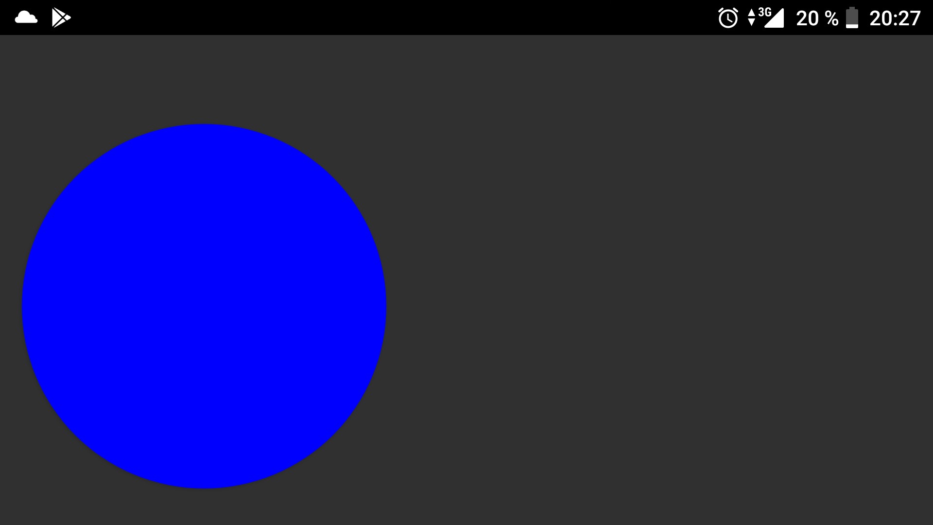
On the android device there is a joystick (a circle, the implementation of which is also in the second part). The Android reads readings from it and converts them into numbers suitable for Arduino: the speed from pixels turns into a value from -255 to 255 (negative ones are in reverse), and also determines the angle. I deliberately gave this task to the phone, since it is much more powerful and easy to cope with counting several hundred values per second.
After the socket is installed, the data is sent in the following format: @ speed # * angle #. @ - means that the following numbers contain speed, # - notifies that the speed value is over, * - the beginning of the angle value, # - to finish the angle recording. The cycle is endless, the commands are sent every 100 milliseconds (the figure is chosen optimal). If nothing is pressed on the android, then nothing is sent.
The algorithm for receiving data is described in detail in the sketch code. He corresponded more than once and, as for me, works perfectly.
Conclusion of the first part
In this article, I tried to reveal all that relates to the physical part of the machine. Most likely, I missed something, so be sure to ask.
But the most interesting, as for me, is left to the second - the Arduino program and the Android application, real magic is going on there, at least for the young me.
If you do not find the answer to some part and you want to poke me personally for the shortcomings, I’m waiting - dendolg1@mail.ru,.
UPD: the second part is already out - habr.com/post/424813
Source: https://habr.com/ru/post/424087/
All Articles