Clean in the boom workshop. Part 2
Or a vacuum cleaner controlled by Bluetooth
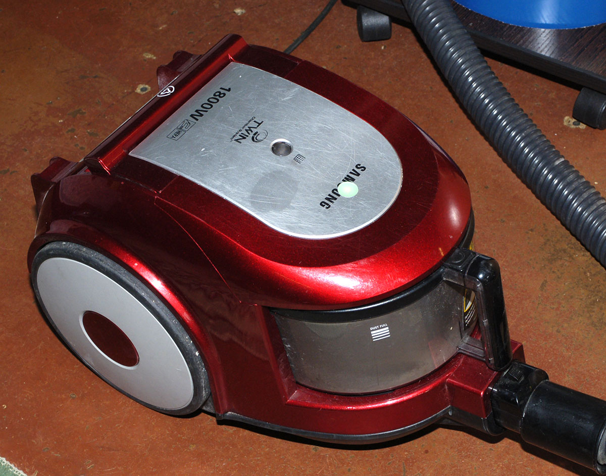
In the first part I told about vacuum cleaners and cyclones for cleaning chips in the workshop. In the comments shared the experience of using different vacuum cleaners and not very good. Now I’ll tell you about how I make prototype boards and devices using the example of a radio-controlled vacuum cleaner. Below are a lot of pictures!
Here is a diagram of the vacuum cleaner from the first part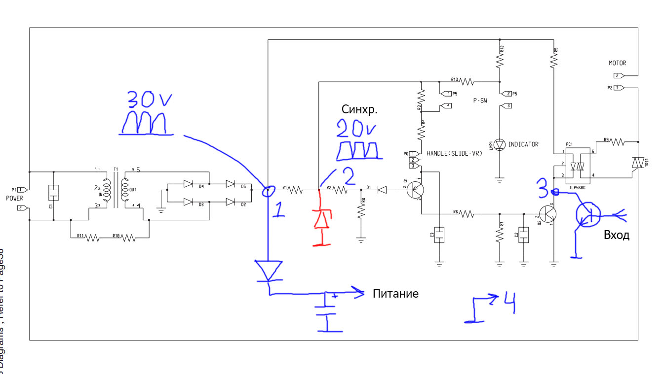
Clickable
Clickable
Now connect the receiver to it.
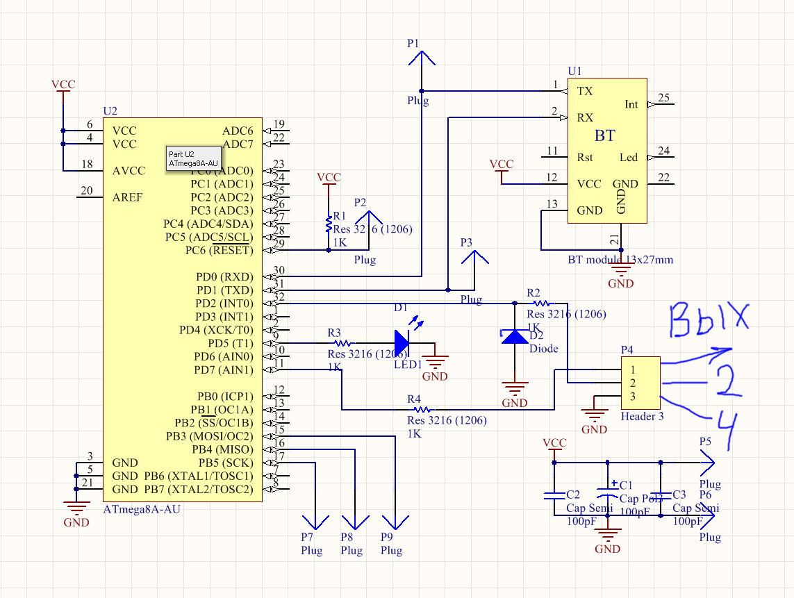
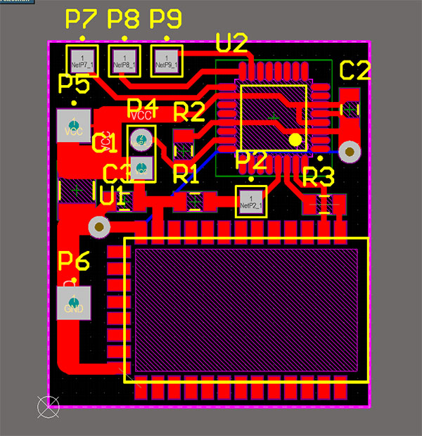
Here is his diagram:
Clickable
There is nothing tricky. Denominations are not affixed. I needed a fee faster. Drawing circuits and boards is the most complete AD :) We power the circuit from the Chinese step-down (at the output of the trance of the vacuum cleaner 30c and we need 3.3). The output of the controller is connected to the base of the additional transistor. We take the synchronization pulse from point 2. Resistor R2 and Zener diode D2 limit the voltage for the controller.
')
The logic of the receiver:
On the rising edge of the synchronization pulse, an interrupt is triggered. In it we start the timer - the counter.
He has 2 comparison registers. On the first - open the vacuum cleaner optocoupler, on the second - close. The response time of the first depends on the selected power and is inversely proportional to it (PWM from the end of the network half-cycle).
The time of the second comparison register is unchanged and it is slightly less than the network half-period (the rest is the guard interval).
From the Bluetooth receiver, we accept packets of 3 bytes. The first 2 of them are IDs - previously known 2 numbers to check the validity of the data so as not to react to any garbage. If the ID is valid, then we light LED1 and react to the 3rd byte, which is power.
Power less than 20% discarded so as not to burn the motor. We recalculate the obtained power value and write to the first comparison register of the timer - the counter that makes the PWM. If valid data does not arrive for a few seconds, we cut down the vacuum cleaner (we assume that the transmitter has fallen off). This is not a tricky algorithm.
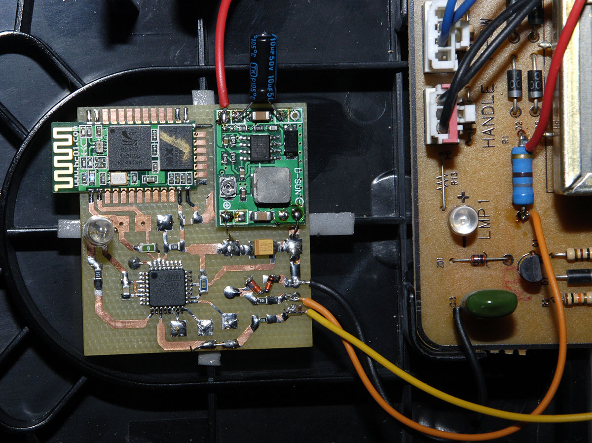
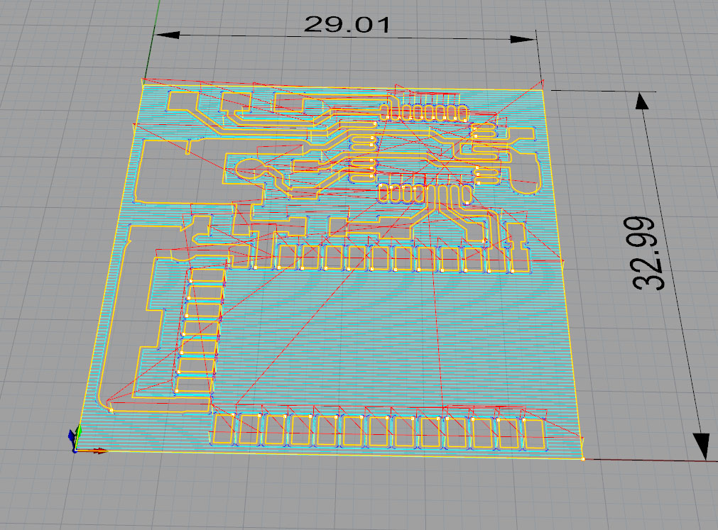
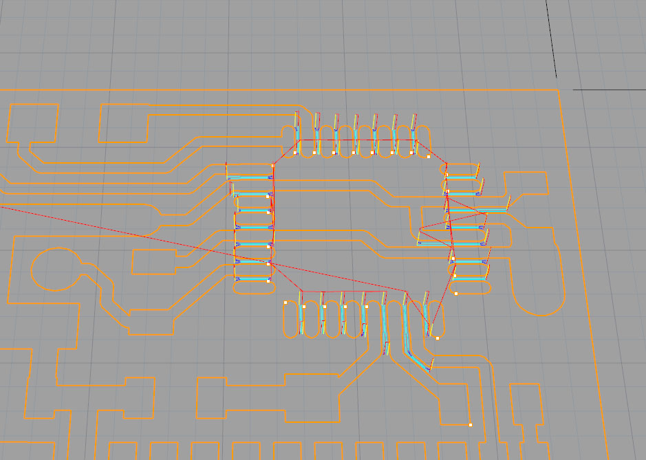
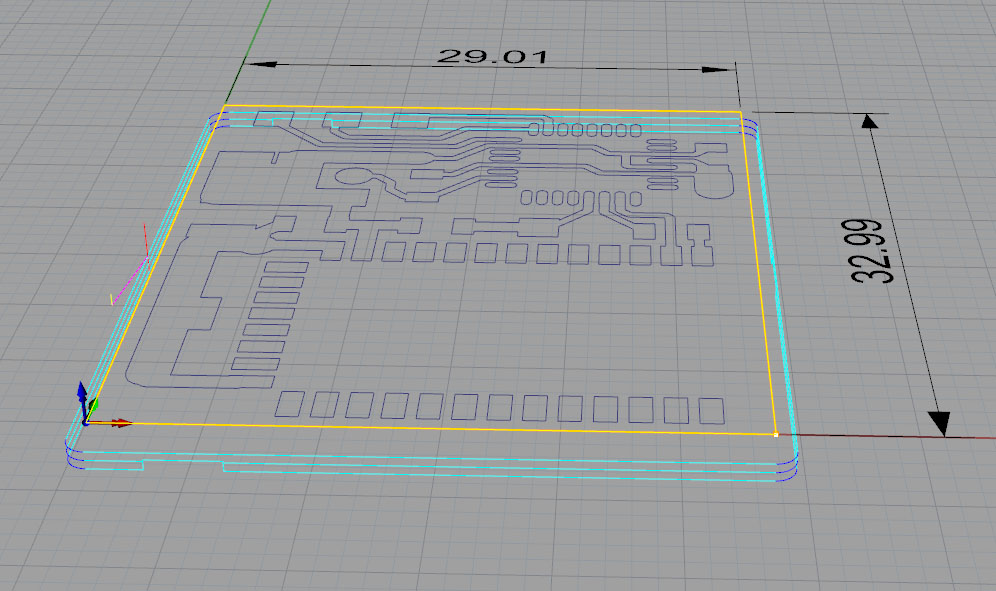
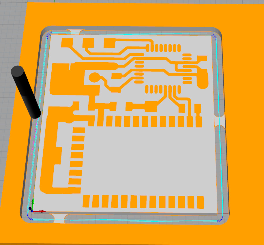
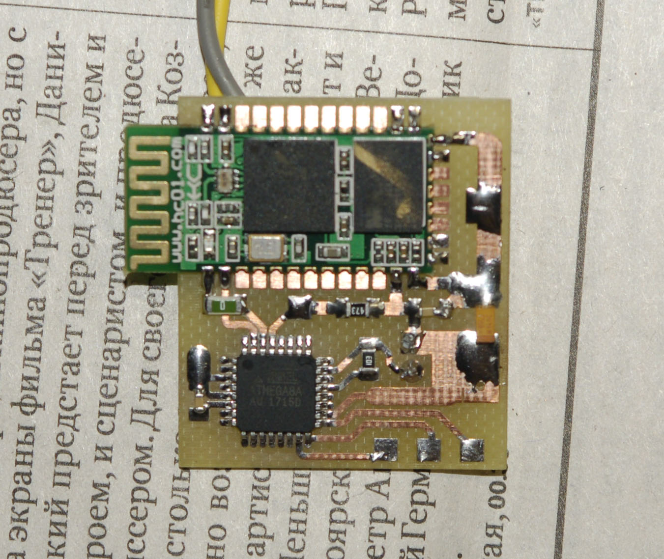
Here is the vacuum cleaner receiver board:
Well, now we make the transmitter board
It's still easier with him. It transmits these same 3 bytes of data several times per second. 3rd byte depends on the position of the resistor on the handle.
Prototypes and pieces of boards I saw on the router. And I don't see it the way I see in most descriptions and reviews. They use special software for engraving boards and simply lead around the paths with a mill. This approach is only suitable for very limited use. For high frequencies or any significant voltages, this is not suitable for sensitive devices. This prototype of the board should be no different from what is obtained by etching. That is, it is necessary to cut out all the copper as it should be, and not just to circle the paths along the contour.
To create programs for milling boards, I use the usual milling software, which I use to make other parts. For example, Rhino CAM. There are many processing strategies, including post processing. That is, it is not necessary to cut the entire board with the thinnest cutter, which must be passed between the legs of the microcircuits and the thinnest tracks. It will take a long time. You can tear down most of the copper with a coarse cutter, and then charge a small one and finish off particularly fine parts. If the board has a lot of empty places, you can use 3 cutters. By the time it turns out is already acceptable. Especially with the automatic measurement of the offset tool. Replaced, poked a button, it measured and sawn further. Then drilling and in the end - cutting out the outline of the board. And all at one time. Thus, high accuracy is not achieved by the LUT method.
For example, I sometimes make prototype boards for testing one familiar office for the production of LED lights. There it is important that the exact positioning of the lenses over the LEDs is necessary so that it precisely fits into the housing and the holes coincide. Fees on aluminum foil. Here for this milling - the most it!
Here is a rough pass transmitter board:
But thin:
On the rough there was a 0.5mm mill, and on a thin one 0.2
Well, cutting the outline of the board:
Bridges so that the board does not fall out of the sheet.
File holes you can feed the software of the machine here the program need not be harvested.
Simulation:
Well, the "eye" for ice on a vacuum cleaner from the "milk" acrylic.
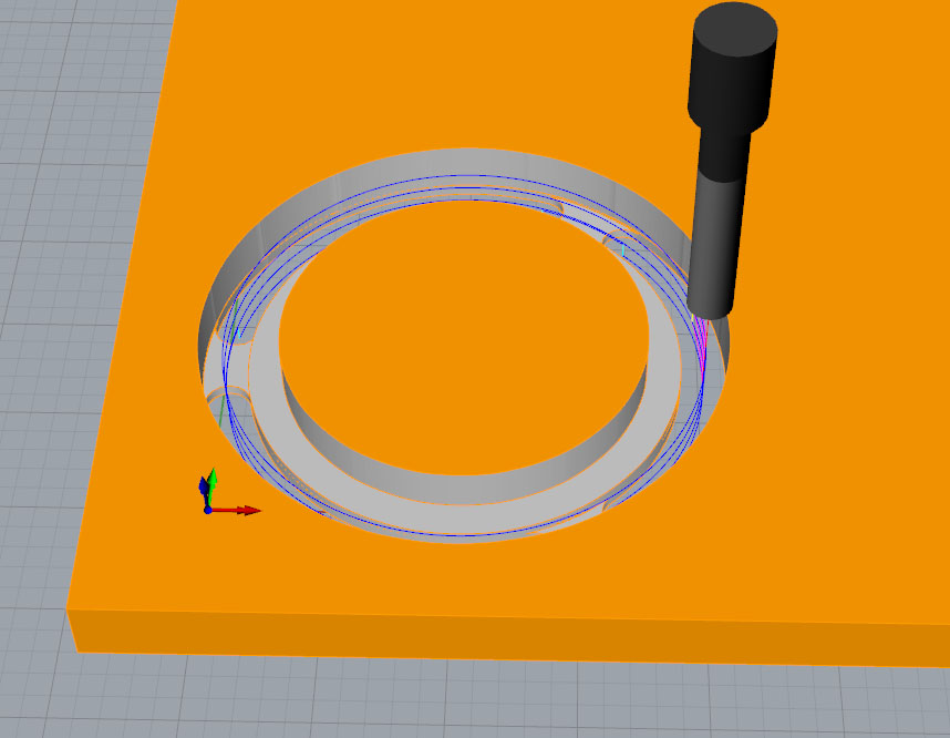
There are also bridges here. On a loose part, you can break the cutter when moving. Well, so that it is not sucked into the vacuum cleaner.
And here is the fee after milling:
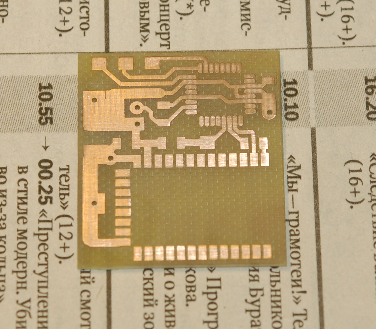
Milling depth 0,03mm
At this depth, the cutter peels off a layer of copper and almost does not touch the PCB. Resource cutters increases. And you can also make thin tracks. Whatever the exact machine (and this is also important), such milling will not work without measurement. Procurement is still a curve! The machine is able to measure the surface of the probe and build the surface of the real workpiece. It then adjusts the program along this surface, and the entire curvature of the workpiece is taken into account in the process. The depth is the same, and the accuracy is high.
We set the grid in steps of about a centimeter and measure ...


Clickable
A contact is connected to the conductive layer of the board (on the right). "Quick" clips - isolated, and under the clip on the left I put a piece of plastic. Such a clip to save so that you can get closer to the edge of the workpiece. The controller of the machine is completely galvanically isolated from the mechanics of the machine and even with the USB port of the computer with which it works. This is so as not to kill the brains with statics, when you saw the plastic and that the interference did not affect the transfer via USB.
Here is the tool I use for boards:
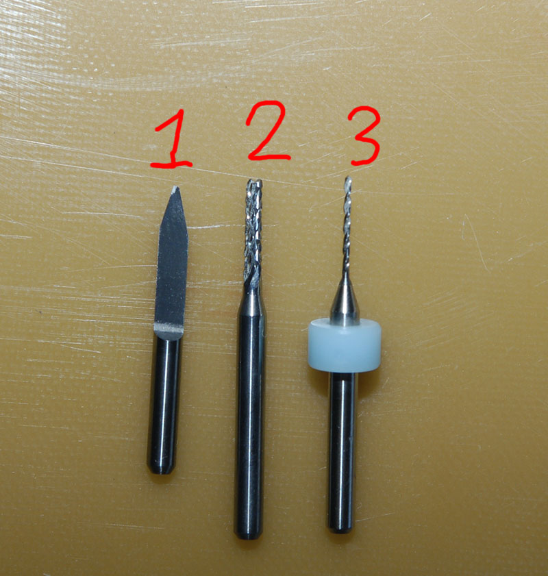
- Engraving cutter.
- "Corn" cutter. I cut out the outlines of the board, large holes and cuts for her, and for very rough demolition of copper. Nibbles textolite like butter.
- Normal drill.
There is also a cutter with a spring for working with a mask (for varnish), but it has not yet been used.
Here is the finished transmitter board:
And here everything is already integrated into the handle of the vacuum cleaner
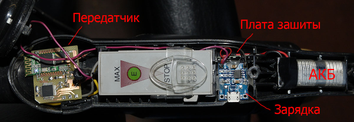
Powered by a lithium can, a micro USB charger is also integrated. Then I will make similar boards of transmitters for integration into the machines. But there will still be synchronization of the inclusion of a vacuum cleaner with the inclusion of the machine.
Somehow like this. Congratulations to all with the early start of the night from Friday to Monday!
Beginning of the story:
Clean in the boom workshop. Part 1
Source: https://habr.com/ru/post/423995/
All Articles