Repair of the printer from the IBM 1401 mainframe of the 60s era
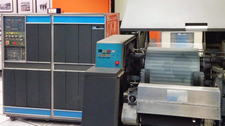
IBM 1401 mainframe (left) at the Museum of Computer History prints the Mandelbrot fractal on a 1403 printer (right)
In the Museum of Computer History, for demonstration, there are two IBM 1401 mainframe workers, but a few weeks ago one of them suddenly had a printer. I helped fix it, but it turned out to be harder than we expected. Along the way, I had to study the logic of checking the errors in the printer, the print buffer, and even low-level signals of the ferrite memory. This article is about our investigation and how we did find a faulty germanium transistor.
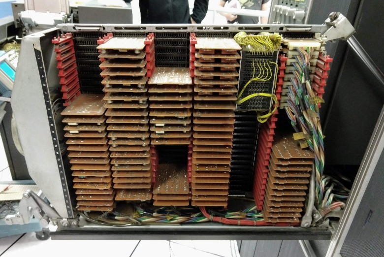
The IBM 1401 mainframe was released in 1959 and became the main bestseller of the mid-60s: more than 10,000 systems were installed. The computer was leased for $ 2,500 per month (about $ 20,000 at current prices): a very low price, allowing even medium-sized enterprises to use it for payroll accounting, billing and many other tasks. The IBM 1401 is made of small printed circuit boards (called SMS cards) connected to blocks called gateboards. The photo below shows 1401 with one of the open baskets. Visible dozens of brown SMS-cards.
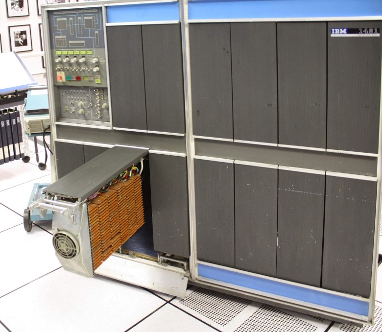
Computer IBM 1401 from one of the opened baskets of boards, where you can see a lot of SMS-cards. Fan on the front cover cools the cards
')
One of the main drivers for the IBM 1401 is the IBM 1403 high-speed linear printer, which output 10 lines per second (IBM argued that it was four times faster than other printers, but competitors dispute this). The 1403 printed excellently: only laser printers from the 1970s managed to outperform this quality. one IBM claims that “even today it remains the quality standard for high-speed shock printing.”
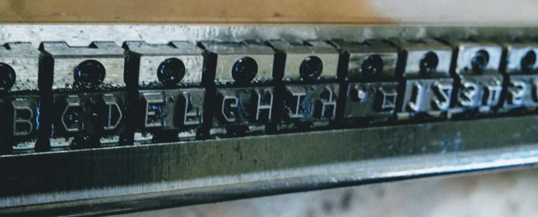
Close-up of a chain with letters (upside down) of an IBM 1403 linear printer
The printer 1403 used a long chain with letters (in the photo above), which rotated at high speed over the paper and ink ribbon. A hammer and an electromagnet are installed on each of the 132 printed positions. At a certain moment, when the desired symbol passed through the hammer, the electromagnet pushed it to the back of the paper, causing the paper and tape to hit the letter on the chain, typing the symbol. 2

IBM 1401 Linear Printer Printing Mechanism. From Reference Guide 1401 , page 11
Unfortunately, the printer at the Computer History Museum had a problem: every time the computer printed a line, the computer stopped due to the “Print Verification” error. Fortunately, the museum has a group of volunteers who help maintain the system in working condition. Among the experts who participated in solving this problem are Ron Williams, Frank King, Marc Verdiell, Karl Crunch, Michael Marinho, Robert Garner and Alexey Toptygin. By the time I came to the rescue, Ron had written a simple test program that repeatedly tried to print a string; he switched to manual mode and turned off error checking. The printer printed the characters as expected. Therefore, we assumed that the problem is in the logical scheme of error messages inside the computer. The strategy was to find the error signal, track it to the source - and determine the cause.
We began by examining the latch pattern (latch), which contains the condition of a print verification error and sends it to the computer. To find the circuit, we checked the documentation: computer-generated wiring diagrams, which are called Automated Logic Diagrams (ALD). Below is a small plot of ALD with a print check trigger (PR CHK LAT). Each rectangle on the ALD corresponds to the pattern on the SMS card, and the lines show the connection of the cards to each other. The deciphering of the text inside the field on the right points to a 2JMX type map that implements the “2 + AO” function, which in modern terms is an AND-OR logic with inverting . The text in each field also indicates the location of the map: its basket, in this case 01A6, and the position of the map inside (F10). So, to check the latch output signal (labeled H) with an oscilloscope, we opened the basket 01A6, found the F10 card, and connected the oscilloscope to contact H.
We found that contact H produces a low signal (error) when contacts F and G are energized, which is the correct behavior for the latch. Contact G (PR CK SAMPLE) is essentially a clock pulse for sampling an error condition, while contact F is the error signal itself. Our next task was to determine what caused the error signal on pin F.
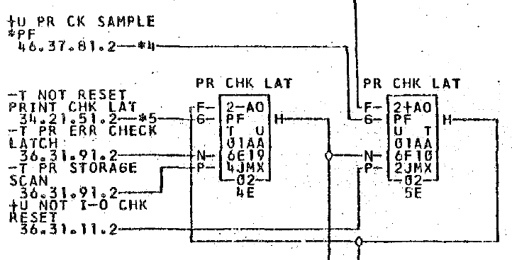
A fragment of an automated logical circuit (ALD) on an IBM 1401 computer, showing the print check latch (PRT CHK LAT). This page is signed as 36.37.21.2.
The documentation also has schemas at the logical level. They are a little easier to understand than the physical connections in the ALD diagrams. The logic below shows the printer error pattern. The right print verification error signal (PRT CHK ERROR) comes out of the latch (PR CHK LAT), which contains an error signal. (This is the same latch as in the ALD diagram above, as understood by the signal names). To her left, several different error states are combined to form an error signal fed into the latch. (Please note that IBM logical symbols do not correspond to standard ones. A semicircle is a logical OR gate, not I. A triangle is an I gate. The “i” symbol in the rectangle is an inverter).
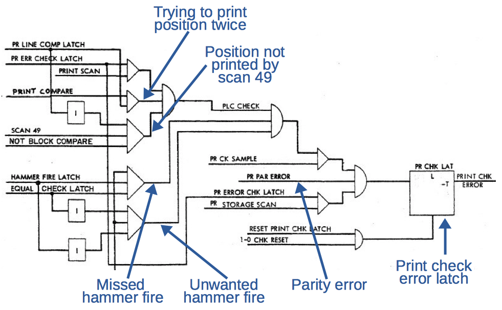
Logic logic for error checking in IBM 1401/1403. From the "Instructions for Logic Circuits" , p. 77, "Print Buffer Controls"
Several conditions can cause print verification errors. 3 , and we thought that the hammer fire test was the most likely candidate. Recall that in the printer 132 hammer to print a string of characters. To check them, two special memory matrices are provided. (1401 uses 4000-character magnetic core memory 4 ; Each bit of memory is a small ferrite ring, which, depending on the magnetization, stores 1 or 0. A grid of 4000 cores forms a memory matrix. Many matrices are located above each other, forming a memory block). Each time a computer decides to run a hammer, it writes it into ferrite memory in the matrix of the check (equal check). When the hammer is actually triggered, the current pulse from the electromagnet stores the bit in the response matrix. five On each scan cycle, the computer compares the two main matrices to verify the correct / incorrect malfunction of the hammers, and, in the event of a discrepancy, gives an error of verification.
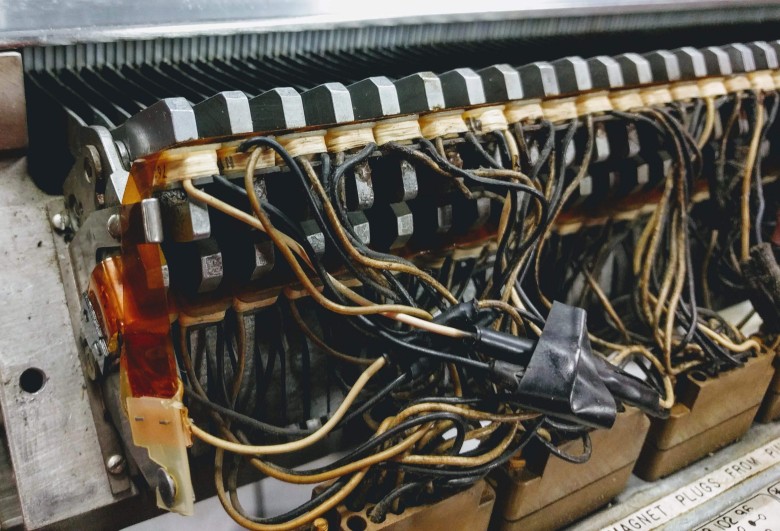
Close-up of electromagnets in an IBM 1403 printer. An electromagnet (when it receives a pulse through its pair of wires) pulls out a metal anchor that controls a hammer, paper, and tape in front of the letter. A total of 132 hammers were installed, one for each column, in two rows of 66 pieces.
After some difficult manipulations 6 we found out that the problem is not with the hammer trigger test, but with another test: “print line complete print (PLC)”. It checks that no more than one character is printed for each row in each column. Here, the third special memory matrix is used - the “row printing completed” matrix. Each time a character is printed, the corresponding bit is set. (For an empty or unprintable character, the bit is set by a separate circuit). At the end of the line (when scanning 49) all the cores of the matrix are checked. If one of them is zero, that is, the printer failed to print this column, an error message is displayed. (On the previous logic circuit, you can see the PLC CHECK signal and the logic that generates it).
The oscilloscope check (below) showed that the PLC CHECK (yellow) is triggered, because the system thinks that the second character is printed in the same column. The cyan signal is the (inverted) PLC bit from the core (PR LINE COMP LATCH); each lower pulse indicates the printing of a symbol in this column. The pink pulse (PRINT COMPARE) indicates the printing of a new symbol. The problem is that cyan and pink signals are reduced at the same time, indicating both the existing symbol and the new symbol in the column. This produces an emergency blue pulse (PLC CHECK), which triggers a yellow pulse (PRINT CHK ERROR from the latch). This diagram is shown in the previous logic diagram with the caption “Trying to print position twice”.
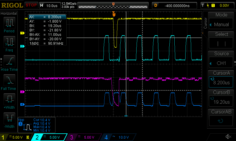
Oscilloscope signal when debugging an IBM 1401 printer
Why does the system think that two characters are printed in a column? This may be for various reasons. On the printout, we saw that in reality the printer prints on paper only one expected symbol, so the circuit for printing the symbol seems to work correctly (PRINT COMPARE, single pink pulse at the top). We checked the empty / non-printable characters scheme, and it correctly detected empty and non-empty columns. Thus, the most likely problem is reading 1 from the memory core (cyan line above, PR LINE COMP LATCH), when there should be 0. But what is really the problem: incorrect core magnetization or incorrect output value?
The logic diagram below shows the mechanism for writing to memory Print Line Compare. The PR LINE COMP INH on the right is the (inverted) signal that is written to the core. eight When scanning 49 (test cycle after printing all 48 characters), this line is energized, clearing the memory. If the symbol is printed, the signal PRINT COMPARE EQUAL is sent. The logic gates on the left define an empty or unprintable symbol. And if the core already has bit 1 (PR LINE COMP LATCH), then bit 1 is overwritten into the core.
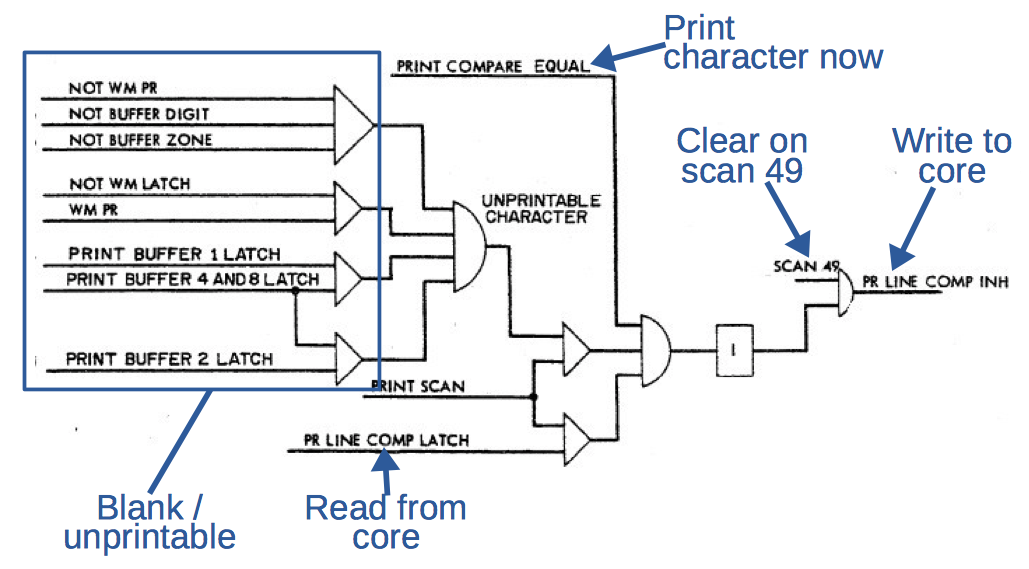
The logic flow of the line completion check logic in IBM 1401/1403. From the "Instructions for Logic Circuits" , p. 77, "Print Buffer Controls"
We found that this scheme wrote down false values 1 into the core, because it read the false values 1 from the core. But so we went in a circle: it is not clear, the initial problem in reading or writing. To solve the problem, we set the oscilloscope on print scan 49 when the PLC bits are reset, and then we looked at the next print scan that reads the cleared bits. We saw how 0 is written (i.e. PR LINE COMP INH high voltage), but we suddenly saw that 1 is returning (PR LINE COMP latch). We realized that something was happening at a low level in ferrite memory.
It should be mentioned that in the standard 1401 system, the control bits of the printer are stored in the main module of ferrite memory, but our system uses a separate “print memory” to improve performance. The performance problem is related to how the printer uses memory: every time the hammer is opposite the desired letter on the tape, the computer reads the corresponding character from the memory and starts the electromagnet if the character in the storage matches the symbol under the hammer. And it turns out that during the printing process memory is continuously used - and the computer during printing cannot perform any calculations. Therefore, a separate printed memory on 132 cores was introduced, which acts as a print buffer. 7 When using such a buffer, the line for printing is first quickly copied from the main memory to the print memory. After that, the computer can continue calculations using the main memory. For each additional option IBM 1401 a monthly fee was charged: printed memory cost $ 386 per month.
This is a basket of cards with print buffer chips. Bundles of yellow wires are connected to the memory unit in the upper right corner.
The photo above shows a basket with cards that implement the function of the printed buffer. The main memory module is a block in the upper right corner with yellow wires. (Separate ferrite cores can be seen in the photo below). Ferrite memory requires a large number of auxiliary circuits. To select the address, driver cards generate X and Y signals. In order to magnetize the core, the signal is combined with a clock pulse, then the control card amplifies the signal and sends it along the inhibit bus that passes through all the cores in the matrix. 9 When reading the core impulses the signal wire. This pulse is amplified by the control card, and then the bit is stored in the latch. The numerous boards in the print memory bin are intended for auxiliary functions in this process.
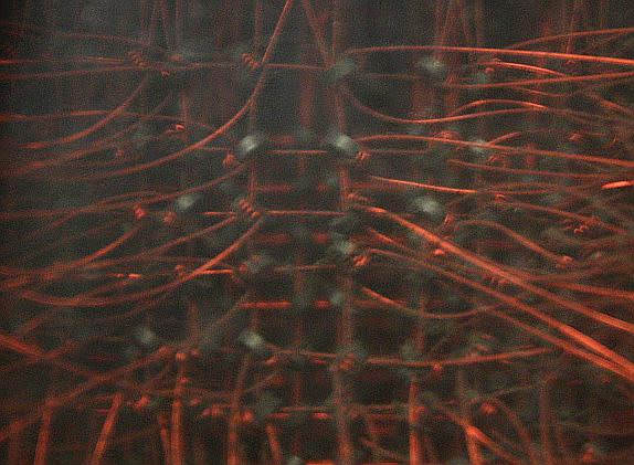
Cores in print buffer. The wiring is different from the usual ferrite memory, because each hammer is directly connected to the test core. The image quality is poor due to the plastic cover over the cores
We investigated the signal amplifier and the latch board on the reading side of ferrite memory. It turned out that they worked correctly, so we switched to the recording side. The HN bus control card appeared to be a candidate for failure, because it operates on high voltage. We changed the map - but we still could not start the printer. Then I tried to look at the input of this card - and found that there was no signal on one line.
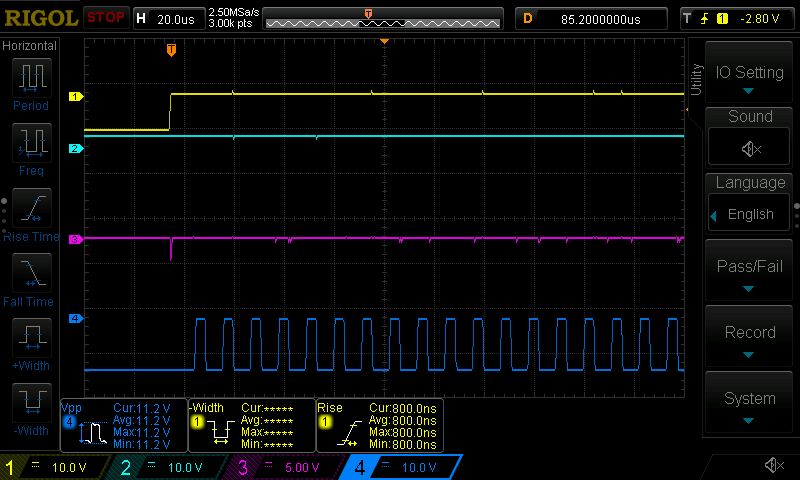
The oscilloscope graph of a bad CHWW card with a logic AND gate is NOT: pink (3) and blue (4) correspond to input signals, cyan output (2) is stuck at high voltage
The missing signal was generated by the CHWW card , the logical NAND gate (NAND), which combines the barring bus signal with a clock pulse before sending it to the control card. I connected the oscilloscope to the inputs and output of the valve and recorded the signal parameters shown in the illustration above. This trace speaks for itself: the output (cyan 2) remains high, even when both inputs (pink 3 and blue 4) change the value from low to high. Immediately it is clear that the valve is faulty. This explains everything: with such a stuck output, only the values 1 are written in the PLC matrix. After printing the symbol, the circuit reads the value 1 from the memory, thinks that the symbol has already been printed, the PLC check fails and a print check error occurs.
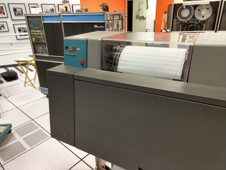
The printer successfully works by printing a power of two.
We replaced this card - and the printer began to print without errors (photo above). This proves that we finally figured out the problem; it turned out to be a simple NAND gate deep in the ferrite memory circuit of the printed buffer. The faulty card is shown below. There are three NAND gates ( parts ) on a diode transistor logic (which IBM calls CDTL - Complemented Transistor Diode Logic). Each gate with two input signals uses one germanium transistor (round metal element) and two diodes (striped glass components on the right). On the left - load resistors (striped) and inductors (beige).
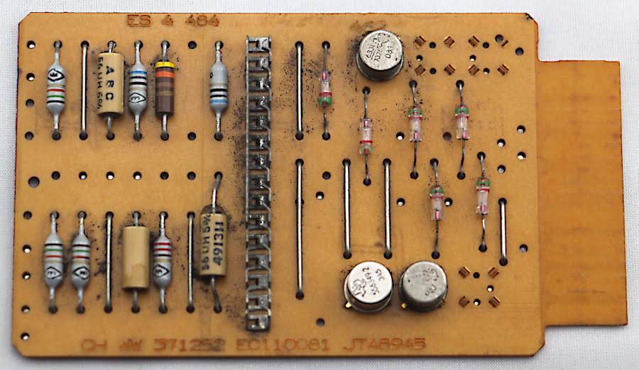
The faulty CHWW card from IBM 1401. It has three NAND gates. Lower left transistor out of order and replaced
I tested the card with a signal generator and found that two of the three gates were working, and the third was stuck on a high output signal, confirming the observations inside 1401. Next, I checked the transistors in diode testing mode on a multimeter. On good transistors, the voltage drops to 0.23 V. (This may seem like a low value, but remember that these are germanium, not silicon transistors). For comparison, the voltage on a bad transistor decreased only to 0.95 V. Finally, we removed the transistors and checked them on the Tektronix 577 vintage characterograph . We thought that the bad transistor would be too weak to drive the latch, but it turned out to be completely killed — a completely flat line on the characterizer.
We opened the transistor on a lathe (lathe) and looked inside. It uses IBM 083 NPN germanium alloy (germanium was used before silicon). The transistor consists of a tiny germanium substrate (the shiny metal square in the photo below) forming the base. Two wires emitter and collector are connected by spots of tin alloy. Under a microscope, it appears that the alloy points have corroded, and the emitter wire does not look securely connected: we suspect that this is the main cause of the failure.
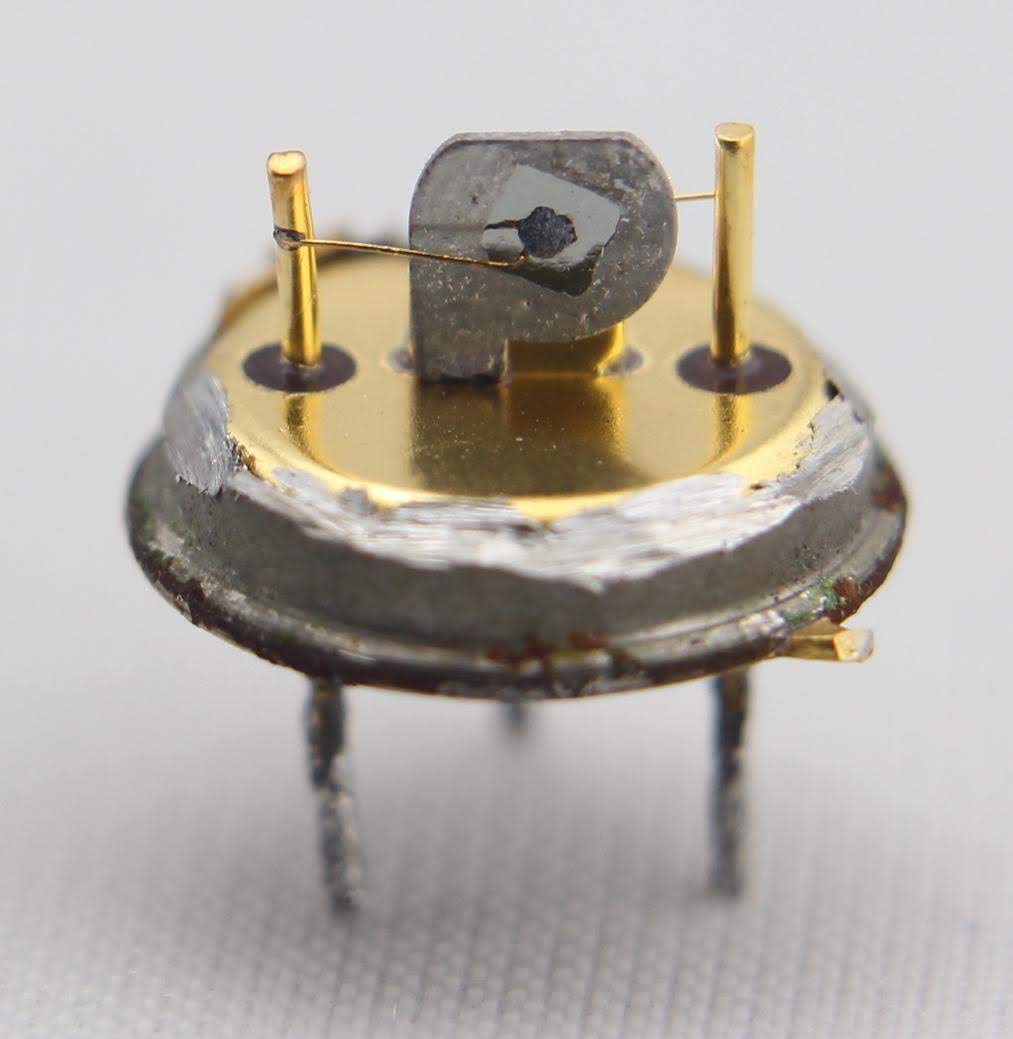
Inside the faulty germanium transistor IBM 083. The silver square in the center is a germanium substrate connected to the cap pins. The point in the middle is an alloy of tin for the collector, which is connected with a wire to the collector pin on the left. A smaller point on the other side of the germanium matrix forms an emitter connected to the contact on the right.
findings
Studying this problem turned out to be more difficult than most problems with the IBM 1401. But we managed to find the cause, replace the faulty card and bring the printer back to life. One advantage of the IBM 1401 over modern systems is that it is not a black box: you can look inside any circuit, even individual transistors. In this case, we were able to find the damaged transistor, which caused the system to crash, and even determine that corrosion probably killed it.
Notes and links
1. One of the reasons for the high-quality printing of the IBM 1403 was the use of a flexible chain, rather than letter plates. Many earlier printers used strips of fonts that moved vertically to select characters, so any offset or synchronization errors changed the vertical position of the characters, resulting in ugly wavy text. In 1403, the chain with letters was rotated horizontally, and the shift consisted only in a barely noticeable change in the distance between the characters. ↑
2. It can be expected that the 132 hammers are combined with 132 letters on the chain and work immediately, but the system does not work that way. Instead, the hammers and letters are located slightly differently, so only one hammer is combined with the chain at a time, and a small movement of the chain leads to the alignment of the other hammer with another letter. (Essentially, they form a nonius). In particular, every 11.1 microseconds, the chain moves 0.001 inches. This leads to a new alignment of the hammer and the type of letter. For mechanical reasons, every third hammer is lined up to the end of the line (1, 4, 7, ...); this is called “subscan” and takes 555 microseconds. Two more subscans make it possible for each hammer to work in a line, forming a print scan of 1.665 milliseconds. 48 scans enable each hammer to print each character, and then the 49th scan is used for error checking (For a more detailed calculation of time, see the Operating Manual , p. 37.).
The scanning and subscanning mechanism may seem overly complex. But he manages to combine the fast "electronic world" with the slower "mechanical world." In particular, combine a hammer with a letter every 11.1 microseconds. The computer reads the character in this column from the memory core, compares it with the letter, and if they match, it starts the hammer. It is important here that the core memory cycle coincides with the hammer alignment time, which allows you to read a symbol from the core for each hammer alignment. If you are interested in how the printing mechanism works, there is such an animation .
One of the nuances is that a hammer blow takes 1.52 milliseconds ( "Operation Guide", p. 32). Thus, you need to run it not when it really aligns with the letter, but for 1.52 milliseconds before this point. ↑
3. A few hard checks on the proper operation of the printer seem redundant. But for a business computer, typing errors can be catastrophic: Imagine that you have the wrong numbers on your paycheck or tax forms. IBM science computers didn’t have as many error checks as business computers did, on the assumption that scientists would notice problems. ↑
4. IBM 1401 stores 4,000 characters in ferrite core memory, not 4096, because it is a decimal machine (that is, a binary-decimal code), with decimal addresses. Memory can be expanded up to 16,000 characters with a dishwasher-sized memory expansion unit. I already wrote about the repair of this device. And here you can read more about ferrite memory 1401. ↑
5. The memory of each beat of the hammer is not recorded by the computer. Instead, each hammer is physically connected with a wire directly to a specific memory core; 132 wires connect electromagnets with cores. When a hammer is triggered, the impulse from the electromagnet goes along the wire through the corresponding core, magnetizing it (These wires are visible on the photo of the cores in the article). ↑
6. It was difficult to determine which signal caused an error at input F due to the “wiring” logic 1401. Because at that time transistors were expensive, IBM used a number of tricks to reduce their number. One of the tricks is mounting OR instead of a valve. The signals were simply combined, so if one of the two had a high level, the same was obtained at the common line. Therefore, we could not simply probe the signals applied to contact F - they were all connected. Instead, we had to turn off the cards to check each signal separately. ↑
7. There are 12 memory matrices in the print buffer, that is, it stores 12 bits in each place. As in conventional memory, 6 bits are occupied by each BCDIC character, one more bit for a word label (metadata indicating field locations) and a parity bit. In addition, the four matrices in the print buffer are designed to detect errors: the hammer trigger signal matrix, the compliance check matrix (recording hammers that should work), the line print completion matrix (PLC, printed character columns) and the error checking matrix caused an error). ↑
8. Writing into ferrite cores seems to be happening the other way around: a high signal on the inhibit bus corresponds to record 0. This is related to the way the cores function. To change the magnetic state of the core, a strong impulse is required; and the pulse with half the voltage does not affect it. The cores are located in a grid with the address lines X and Y, which give a signal to select a specific core. Many matrices are stacked on top of each other, each for one bit. A half-voltage signal is sent along each line, so only at the intersection of the required lines X and Y there is enough current to magnetize the core to state 1. Each matrix has a bar which passes through all the cores of the matrix. When writing 1, the bus does not receive current, which magnetizes the core to the specified address, as described above. To write 0 to the matrix,A half current is fed to the bus in the opposite direction. As a result, none of the cores gets enough current to switch, and the core at the desired address remains in state 0. Thus, due to the correct installation of the bus, you can record 0 and 1 at the correct addresses. ↑
9. To print checks cm. In "Command logic" on p. 98. For information about the printer, see 1403. In "Description of IBM in 1403 Components" , "Maintenance Guide 1403 printer maintenance" and "Owner's Manual 1403 printers" . See also this short article on the 1403 printer in IEEE Spectrum magazine. A detailed description of IBM 1401 - in "IBM 1401: Modern Theory of Work . " ↑
Source: https://habr.com/ru/post/423831/
All Articles