Creating a logical game for the gaming platform
Hello.
I want to share my story of acquaintance with the gaming platform Gameduino 3, and also talk a little about programming the simplest logic game for this platform, used in conjunction with Arduino Uno.
What is Gameduino 3? Gameduino 3 is an expansion card that allows you to turn an Arduino into a modern pocket (meaning size) game console. To my surprise, I could not find any detailed information on this board in Habré. I would like to fill this gap, especially since the board, in my opinion, deserves attention.
')
The author of the project called Gameduino is James Bowman, who in 2011 created the first version of the board. Then it was positioned as a VGA module for the Arduino. The board was called Gameduino and was made on the basis of the Xilinx Spartan-3A programmable logic matrix FPGA. The board has been fitted with connectors for connecting a VGA monitor and stereo speakers.
In 2013, the second version of the board was released - Gameduino 2, which, unlike the previous version, already had a 4.3-inch resistive touchscreen display with a resolution of 480x272, a 3-axis accelerometer, a microSD memory card slot, and an audio output to headphones.
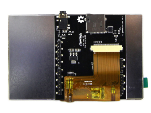
The “heart” of the board is the EVE (Embedded Video Engine - in Russian can be translated as “embedded video module”) FT800, which has powerful computational capabilities, combining several functions simultaneously: image formation and output to the TFT display screen, touch screen processing, sound generation.
In 2017, the third version of the board was released - Gameduino 3, which apparently does not differ much from Gameduino 2. Instead of FT800, the new graphics controller FT810 is used, which has backward software compatibility with FT800 (i.e., all the code for Gameduino2 runs on Gameduino3), but at the same time it has 4 times more computational capabilities, such as faster hardware JPEG decoding, video decoding, increased up to 1 MB of RAM, etc.
James Bowman has published for his project a library with many examples that work "right out of the box." The current library that I managed to find is here . Programming Guide (in English), where everything is described in detail. Lots of useful information on installing IDEs, etc., etc.
Somehow, wandering across the expanses of theBolshoi Theater of the Internet, I came across an interesting project for Arduino - a logical game "Columns" , written under the usual inexpensive Chinese color display of 128x160 pixels. I wanted to repeat this game, but on my own board, I’ll call it FT810 (after the name of the graphics processor), which I already had in my hands. I also had time to study the programming manual and examples from the library, so my hands simply “itched” from the desire to write something of my own. What I immediately and started.
The first thing I had to do was display the text on the screen.
Due to the presence of built-in fonts, text output on the screen is quite easy. I will give a demo sketch from the library (with my comments):
Next, it was necessary to draw geometric shapes, for example: lines.
To draw lines, you must use Begin (LINES) or Begin (LINE_STRIP).
LINES connects each pair of vertices, while LINE_STRIP merges all vertices together.
I will cite the following demoschette from the library (with my comments):
From drawing lines go to drawing rectangles.
To draw rectangles, use Begin (RECTS) and set the opposite corners of the rectangle. The order of the two corners does not matter. Rectangles are drawn with rounded corners, using the width of the current line as the corner radius. Rounded corners go beyond the boundaries of the rectangle, therefore increasing the radius of the corner leads to an increase in the number of pixels. This example draws a rectangle 420 × 20 three times with an increase in the corner radius.
Let's move on to drawing a circle - the basis of future touch buttons. Let's go back to the first example with the text and add a few lines to the loop ().
To work with touch buttons, it is necessary to organize the processing of pressing the touch screen. This is done as follows. In short, I will explain the principle. Each pixel (point) on the screen has a color. It also has an invisible tag value, which can be assigned to a point (or to an entire line, circle, rectangle, etc) object and later used to detect tangencies of this object. The following sketch shows an example of setting the tag value for color circles to 100 and 101.
I gave examples of basic operations, using which it was already possible to safely move on to creating a game. Of course, the game was not created from scratch, but the basis was taken as a ready-made working code, which was adapted (with preservation of graphics), so the original version of the game was very similar to the original.
The first version of the design of the game:

After playing for several days, I wanted to change something in the design, for example, to add something different, unusual, instead of a white background. And then I remembered one example from the library, in which the starry sky was in the background:
To add a picture of the starry sky as a background, I had to do the following: first, change the black color of the lines and the text to white (so that they were visible on a black background), write a slotgag.gd2 file in which the image is stored to the micro SD card add to the project folder slotgag_assets.h and add the necessary 8 lines of code to the sketch.
As a result, the game has acquired this form:

And of course, what kind of game without sound design? It remains to add sound effects, especially since they are presented in good quality and variety.
Gameduino 2/3 has two sound systems. The first, a synthesizer, can generate a set of fixed sounds and musical notes. A synthesizer is useful for quickly adding sound to a project, but since the sound set is fixed, it is not very flexible. The second is reproduction of the sample. It reproduces the sampled sound from the main memory in various formats. This system is much more flexible, but you will need to prepare and load samples into RAM.
I used a fixed sound synthesizer. The synthesizer provides several short “drum” sounds, mainly for use in user interfaces. To play a sound, you need to call GD.play () with a sound ID. Full list of available sounds:
CLICK
SWITCH
COWBELL
NOTCH
Hihat
KICKDRUM
Pop
CLACK
CHACK
The result was this sketch:
I believe that I have completed the task of creating my first working sketch for this board. I hope that at least one person was interested in reading my story. Criticism and comments are welcome. The plans do not stop, move on and, of course, share experience and knowledge.
To demonstrate the operation of the board, I post a video with sound (Caution! Loud sound!).
Thanks for attention.
I want to share my story of acquaintance with the gaming platform Gameduino 3, and also talk a little about programming the simplest logic game for this platform, used in conjunction with Arduino Uno.
What is Gameduino 3? Gameduino 3 is an expansion card that allows you to turn an Arduino into a modern pocket (meaning size) game console. To my surprise, I could not find any detailed information on this board in Habré. I would like to fill this gap, especially since the board, in my opinion, deserves attention.
')
A bit of history
The author of the project called Gameduino is James Bowman, who in 2011 created the first version of the board. Then it was positioned as a VGA module for the Arduino. The board was called Gameduino and was made on the basis of the Xilinx Spartan-3A programmable logic matrix FPGA. The board has been fitted with connectors for connecting a VGA monitor and stereo speakers.
Gameduino (1) features:
background graphics:
foreground graphics:
audio output:
The image is displayed on the screen of a standard VGA monitor with a resolution of 400x300 pixels,
Compatible with any standard VGA monitors with a resolution of 800x600 pixels.
- VGA video output with a resolution of 400x300 pixels, 512 colors;
- All color gamut is processed in FPGA with 15-bit accuracy;
background graphics:
- the area of the symbolic background graphics 512x512 points;
- 256 characters, each with an independent 4-color palette;
- implemented the effect of wrapping text lines with pixel anti-aliasing;
foreground graphics:
- each sprite has a resolution of 16x16 pixels;
- each sprite can have a 256, 16 or 4 color palette;
- support for 4-way rotation and horizontal rotation algorithms;
- 96 sprites per raster line, 1536 texture elements per raster line;
- a mechanism for detecting possible intersections of sprites;
audio output:
- 12-bit two-channel frequency synthesizer;
- 64-voice polyphony in the frequency range of 10 - 8000 Hz.
The image is displayed on the screen of a standard VGA monitor with a resolution of 400x300 pixels,
Compatible with any standard VGA monitors with a resolution of 800x600 pixels.
In 2013, the second version of the board was released - Gameduino 2, which, unlike the previous version, already had a 4.3-inch resistive touchscreen display with a resolution of 480x272, a 3-axis accelerometer, a microSD memory card slot, and an audio output to headphones.
The “heart” of the board is the EVE (Embedded Video Engine - in Russian can be translated as “embedded video module”) FT800, which has powerful computational capabilities, combining several functions simultaneously: image formation and output to the TFT display screen, touch screen processing, sound generation.
Functional diagram of the graphics controller FT800
The structure of the chip includes the following functional blocks: a graphic controller, an audio controller, a resistive touch panel controller. The FT800 is designed to control displays with resolutions up to 512 x 512 pixels. The FT800 also supports LCD WQVGA (480 x 272) and QVGA (320 x 240). EVE (Embedded Video Engine) FT800 is a turnkey solution for creating a graphical user interface. The microcircuit forms display control signals, has built-in graphic functions for displaying points, lines, raster images, volume buttons, texts, etc.
The structure of the chip includes the following functional blocks: a graphic controller, an audio controller, a resistive touch panel controller. The FT800 is designed to control displays with resolutions up to 512 x 512 pixels. The FT800 also supports LCD WQVGA (480 x 272) and QVGA (320 x 240). EVE (Embedded Video Engine) FT800 is a turnkey solution for creating a graphical user interface. The microcircuit forms display control signals, has built-in graphic functions for displaying points, lines, raster images, volume buttons, texts, etc.
System structure based on the FT800 graphics controller
The image is generated based on a set of commands (display list) that is transmitted to the managing microcontroller on the FT800 via the I2C or SPI interface (in the Gameduino 2, the connection between the Arduino and the FT800 is done via the SPI interface). Opportunities FT800 can significantly relieve the host system controller.

For example, to display a series of buttons, it is enough to send a single command to the graphics controller (four 32-bit words), and the FT800 will automatically generate an image of these buttons on the TFT display screen. The command set of FTDI graphics controllers includes more than 50 functions with which you can display various images on the display screen with various effects.
Detailed guidance on programming the controller and examples of working with various design environments can be found in the Application Notes on the FTDI website.
In Russian, a good description of the functionality, general principles and examples of work is here .
Gameduino 2 features:
The sound output is via an amplified headphone jack.
The system supports the selection of embedded samples and tools.
The controller's ROM is already protected:
And, of course, you can load your own fonts and sound bites into 256 KB RAM.
Using the Arduino platform is not a prerequisite: the Gameduino 2 board can be connected to any microcontroller or SPI microcontroller board.
- screen resolution of 480x272 pixels in 24-bit color;
- a set of commands in the style of OpenGL;
- up to 2000 sprites of any size;
- 256 KB of video memory;
- smooth sprite rotation and scaling with bilinear filtering;
- smooth circle and linear hardware drawing - 16x anti-aliasing;
- JPEG hardware decoding;
- Built-in rendering of gradients, text, dials and buttons.
The sound output is via an amplified headphone jack.
The system supports the selection of embedded samples and tools.
The controller's ROM is already protected:
- high-quality fonts (6 sizes);
- samples of 8 musical instruments played by a MIDI note;
- samples of 10 percussion sounds.
And, of course, you can load your own fonts and sound bites into 256 KB RAM.
Using the Arduino platform is not a prerequisite: the Gameduino 2 board can be connected to any microcontroller or SPI microcontroller board.
In 2017, the third version of the board was released - Gameduino 3, which apparently does not differ much from Gameduino 2. Instead of FT800, the new graphics controller FT810 is used, which has backward software compatibility with FT800 (i.e., all the code for Gameduino2 runs on Gameduino3), but at the same time it has 4 times more computational capabilities, such as faster hardware JPEG decoding, video decoding, increased up to 1 MB of RAM, etc.
Gameduino 3 features:
- video decoder for full-screen 30 fps video;
- 1 megabyte of internal RAM;
- connectors for microSD card and audio output;
- high-contrast LCD panel with a diagonal of 4.3 "480x272 with a resistive touch screen;
- support for maps created using the Tiled Map editor;
- Download PNG image from microSD;
- JPEG accelerated decoding;
- hardware portrait / landscape switching;
- support for Arduino, ESP8266 and Teensy 3.2;
- online tools for preparing graphics, audio, fonts and videos;
James Bowman has published for his project a library with many examples that work "right out of the box." The current library that I managed to find is here . Programming Guide (in English), where everything is described in detail. Lots of useful information on installing IDEs, etc., etc.
Programming
Somehow, wandering across the expanses of the
The first thing I had to do was display the text on the screen.
Due to the presence of built-in fonts, text output on the screen is quite easy. I will give a demo sketch from the library (with my comments):
Sketch helloworld.ino

#include <EEPROM.h> #include <SPI.h> #include <GD2.h> void setup() { Serial.begin(1000000); // , 1000000 GD.begin(0); // , . } void loop() { GD.ClearColorRGB(0x103000); // . GD.Clear(); // ( ) GD.cmd_text( // , GD.w / 2, // 2 GD.h / 2, // 2 31, // OPT_CENTER, // , . "Hello world"); // GD.swap(); // ( ). } Next, it was necessary to draw geometric shapes, for example: lines.
To draw lines, you must use Begin (LINES) or Begin (LINE_STRIP).
LINES connects each pair of vertices, while LINE_STRIP merges all vertices together.
I will cite the following demoschette from the library (with my comments):
Sketch lines.ino
Lines on the screen:
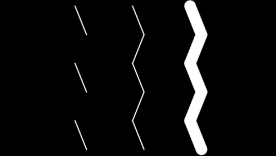
#include <EEPROM.h> #include <SPI.h> #include <GD2.h> void setup() { Serial.begin(1000000); // , 1000000 . GD.begin(); // , . } static void zigzag(int x) { GD.Vertex2ii(x - 10, 10); // GD.Vertex2ii(x + 10, 60); // () GD.Vertex2ii(x - 10, 110); GD.Vertex2ii(x + 10, 160); GD.Vertex2ii(x - 10, 210); GD.Vertex2ii(x + 10, 260); // () } void loop() { GD.Clear(); // ( - 0000000) GD.Begin(LINES); // zigzag(140); // zigzag - GD.Begin(LINE_STRIP); // zigzag(240); GD.LineWidth(16 * 10); // 1/16 , .. 1/16 * 16 * 10 = 10 GD.Begin(LINE_STRIP); zigzag(340); GD.swap(); // ( ). } Lines on the screen:
From drawing lines go to drawing rectangles.
To draw rectangles, use Begin (RECTS) and set the opposite corners of the rectangle. The order of the two corners does not matter. Rectangles are drawn with rounded corners, using the width of the current line as the corner radius. Rounded corners go beyond the boundaries of the rectangle, therefore increasing the radius of the corner leads to an increase in the number of pixels. This example draws a rectangle 420 × 20 three times with an increase in the corner radius.
Sketch rectangles.ino
Result:

#include <EEPROM.h> #include <SPI.h> #include <GD2.h> void setup() { Serial.begin(1000000); // , 1000000 . GD.begin(); // , . } void loop() { GD.Clear(); // ( - 0000000) GD.Begin(RECTS); // GD.Vertex2ii(30, 30); // GD.Vertex2ii(450, 50); // GD.LineWidth(16 * 10); // 1/16 , .. 1/16 * 16 * 10 = 10 GD.Vertex2ii(30, 120); // GD.Vertex2ii(450, 140); // GD.LineWidth(16 * 20); // 1/16 , .. 1/16 * 16 * 20 = 20 GD.Vertex2ii(30, 220); // GD.Vertex2ii(450, 230); // GD.swap(); // ( ) } Result:
Let's move on to drawing a circle - the basis of future touch buttons. Let's go back to the first example with the text and add a few lines to the loop ().
Sketch with drawing color circles
Result:

#include <EEPROM.h> #include <SPI.h> #include <GD2.h> void setup() { Serial.begin(1000000); // , 1000000 GD.begin(0); // , . } void loop() { GD.ClearColorRGB(0x103000); // . GD.Clear(); // ( ) GD.cmd_text( // , GD.w / 2, // 2 GD.h / 2, // 2 31, // OPT_CENTER, // , "Hello world"); // GD.PointSize(16 * 30); // () 1/16 , .. 1/16 * 16 * 30 = 30 GD.Begin(POINTS); // () GD.ColorRGB(0xff8000); // orange GD.Vertex2ii(220, 100); // () 220,100 GD.ColorRGB(0x0080ff); // teal GD.Vertex2ii(260, 170); // () 260,170 GD.swap(); // ( ) } Result:
To work with touch buttons, it is necessary to organize the processing of pressing the touch screen. This is done as follows. In short, I will explain the principle. Each pixel (point) on the screen has a color. It also has an invisible tag value, which can be assigned to a point (or to an entire line, circle, rectangle, etc) object and later used to detect tangencies of this object. The following sketch shows an example of setting the tag value for color circles to 100 and 101.
Sketch with touchscreen processing
Now, when the system detects a touch on any circle, it reports its sensor code, in this case 100 or 101. When you click on objects (colored circles), the values of the tags corresponding to the pressed objects appear on the screen in the serial port window:

#include <EEPROM.h> #include <SPI.h> #include <GD2.h> void setup() { Serial.begin(1000000); // , 1000000 GD.begin(0); // , . } void loop() { GD.ClearColorRGB(0x103000); // . GD.Clear(); // ( ) GD.cmd_text( // , GD.w / 2, // 2 GD.h / 2, // 2 31, // OPT_CENTER, // , "Hello world"); // GD.PointSize(16 * 30); // () 1/16 , .. 1/16 * 16 * 30 = 30 GD.Begin(POINTS); // () GD.ColorRGB(0xff8000); // orange GD.Tag(100); // () GD.Vertex2ii(220, 100); // () 220,100 GD.ColorRGB(0x0080ff); // teal GD.Tag(101); // () GD.Vertex2ii(260, 170); // () 260,170 GD.swap(); // ( ) GD.get_inputs(); // if(GD.inputs.tag > 0) // Serial.println(GD.inputs.tag); // “” } Now, when the system detects a touch on any circle, it reports its sensor code, in this case 100 or 101. When you click on objects (colored circles), the values of the tags corresponding to the pressed objects appear on the screen in the serial port window:
I gave examples of basic operations, using which it was already possible to safely move on to creating a game. Of course, the game was not created from scratch, but the basis was taken as a ready-made working code, which was adapted (with preservation of graphics), so the original version of the game was very similar to the original.
The first version of the design of the game:
After playing for several days, I wanted to change something in the design, for example, to add something different, unusual, instead of a white background. And then I remembered one example from the library, in which the starry sky was in the background:
Demonstration sketch slotgag.ino
View:

In order not to go deep into the wilds, I did not comment on all the code, but commented on only the necessary lines of code that I copied into my working sketch.
#include <EEPROM.h> #include <SPI.h> #include <GD2.h> #include "slotgag_assets.h" // void setup() { Serial.begin(1000000); GD.begin(); LOAD_ASSETS(); // } void loop() { GD.Clear(); // ( , ) GD.ColorMask(1, 1, 1, 0); // R, G, B, GD.Begin(BITMAPS); // GD.BitmapHandle(BACKGROUND_HANDLE); // - GD.BitmapSize(NEAREST, REPEAT, REPEAT, 480, 272); // GD.Vertex2ii(0, 0, BACKGROUND_HANDLE); // 0,0 GD.ColorMask(1, 1, 1, 1); GD.ColorRGB(0xa0a0a0); GD.Vertex2ii(240 - GAMEDUINO_WIDTH / 2, 136 - GAMEDUINO_HEIGHT / 2, GAMEDUINO_HANDLE); static int x = 0; GD.LineWidth(20 * 16); GD.BlendFunc(DST_ALPHA, ONE); GD.Begin(LINES); GD.Vertex2ii(x, 0); GD.Vertex2ii(x + 100, 272); x = (x + 20) % 480; //' }a GD.swap(); } View:
In order not to go deep into the wilds, I did not comment on all the code, but commented on only the necessary lines of code that I copied into my working sketch.
To add a picture of the starry sky as a background, I had to do the following: first, change the black color of the lines and the text to white (so that they were visible on a black background), write a slotgag.gd2 file in which the image is stored to the micro SD card add to the project folder slotgag_assets.h and add the necessary 8 lines of code to the sketch.
As a result, the game has acquired this form:
And of course, what kind of game without sound design? It remains to add sound effects, especially since they are presented in good quality and variety.
Gameduino 2/3 has two sound systems. The first, a synthesizer, can generate a set of fixed sounds and musical notes. A synthesizer is useful for quickly adding sound to a project, but since the sound set is fixed, it is not very flexible. The second is reproduction of the sample. It reproduces the sampled sound from the main memory in various formats. This system is much more flexible, but you will need to prepare and load samples into RAM.
I used a fixed sound synthesizer. The synthesizer provides several short “drum” sounds, mainly for use in user interfaces. To play a sound, you need to call GD.play () with a sound ID. Full list of available sounds:
CLICK
SWITCH
COWBELL
NOTCH
Hihat
KICKDRUM
Pop
CLACK
CHACK
Total
The result was this sketch:
Sketch Columns.ino
#include <SPI.h> #include <GD2.h> #include <avr/eeprom.h> #include "slotgag_assets.h" #define TAG_BUTTON_LEFT 201 #define TAG_BUTTON_RIGHT 202 #define TAG_BUTTON_ROT 203 #define TAG_BUTTON_DROP 204 #define X_BUTTON_LEFT 50 #define Y_BUTTON_LEFT 222 #define X_BUTTON_RIGHT 430 #define Y_BUTTON_RIGHT 222 #define X_BUTTON_ROT 430 #define Y_BUTTON_ROT 50 #define X_BUTTON_DROP 50 #define Y_BUTTON_DROP 50 // Color definitions #define BLACK 0x000000 #define RED 0xFF0000 #define GREEN 0x00FF00 #define BLUE 0x0000FF #define YELLOW 0xFFFF00 #define MAGENTA 0xFF00FF #define CYAN 0x00FFFF #define WHITE 0xFFFFFF #define DISPLAY_MAX_X 480 #define DISPLAY_MAX_Y 272 #define MaxX 8 #define MaxY 17 #define SmeX 3 #define SmeY 3 #define razmer 18 #define NumCol 6 #define MaxLevel 8 #define NextLevel 80 #define DISP_LEFT ((DISPLAY_MAX_X - MaxX*razmer)/2 - 2) #define DISP_RIGHT ((DISPLAY_MAX_X + MaxX*razmer)/2 + 2) #define DISP_TOP ((DISPLAY_MAX_Y - (MaxY-4)*razmer)/2 - 2) #define DISP_BOT ((DISPLAY_MAX_Y + (MaxY-4)*razmer)/2 + 2) uint8_t MasSt[MaxX][MaxY], MasTmp[MaxX][MaxY], fignext[3]; uint8_t Level=1, dx, dy, tr, flfirst=1; uint32_t MasCol[]={WHITE, BLACK, RED, BLUE, GREEN, YELLOW, MAGENTA, CYAN}; unsigned long Counter, Score=0, TScore=0, Record=0, myrecord; uint16_t tempspeed = 1000; bool fl, Demo=true, Arbeiten=false, FlZ=false; int8_t x,y; int8_t mmm [4][2]={{-1,0},{0,-1},{1,0},{0,1}}; uint16_t MasSpeed[MaxLevel]={500,450,400,350,300,250,200,100}; uint8_t state_game = 0; unsigned long time_count; byte prevkey; uint32_t btn_color = 0xff0000; /****************************************************************************************************************/ void setup(void) { Serial.begin(1000000); Serial.println("Columns"); GD.begin(); LOAD_ASSETS(); GD.BitmapHandle(BACKGROUND_HANDLE); GD.BitmapSize(NEAREST, REPEAT, REPEAT, 480, 272); randomSeed(analogRead(5)); myrecord = eeprom_read_byte((unsigned char *)1); time_count = millis() + 1000; } static struct { byte t, note; } pacman[] = { { 0, 71 }, { 2, 83 }, { 4, 78 }, { 6, 75 }, { 8, 83 }, { 9, 78 }, { 12, 75 }, { 16, 72 }, { 18, 84 }, { 20, 79 }, { 22, 76 }, { 24, 84 }, { 25, 79 }, { 28, 76 }, { 32, 71 }, { 34, 83 }, { 36, 78 }, { 38, 75 }, { 40, 83 }, { 41, 78 }, { 44, 75 }, { 48, 75 }, { 49, 76 }, { 50, 77 }, { 52, 77 }, { 53, 78 }, { 54, 79 }, { 56, 79 }, { 57, 80 }, { 58, 81 }, { 60, 83 }, { 255, 255 } }; //================================================== void loop(void) { GD.get_inputs(); byte key = GD.inputs.tag; int8_t VAL = 0; if (prevkey == 0x00) { switch (key) { case TAG_BUTTON_LEFT: VAL = -1; break; case TAG_BUTTON_RIGHT: VAL = 1; break; case TAG_BUTTON_ROT: if (!FlZ) { GD.play(HIHAT); byte aa=MasSt[x][y]; MasSt[x][y]=MasSt[x][y+2]; MasSt[x][y+2]=MasSt[x][y+1]; MasSt[x][y+1]=aa; } break; case TAG_BUTTON_DROP: if (Arbeiten) { if (!FlZ) { tempspeed=50; GD.play(NOTCH); } } else { GD.play(CLICK); Demo=false; NewGame(); } break; } } prevkey = key; if (VAL!=0 && fig_shift(VAL) && !FlZ) { for (byte i=0;i<3;i++) { MasSt[x+VAL][y+i]=MasSt[x][y+i]; MasSt[x][y+i]=0; } x=x+VAL; } ProcGame(); ViewStacan(); GD.swap(); } //================================================== // redraw one square void ViewQuad(byte i,byte j,byte mycolor) { if (j<3) return; uint16_t wy=DISP_TOP + SmeY+(j-3)*razmer-j; uint16_t wx=DISP_LEFT + SmeX+i*razmer-i; if (mycolor!=0) { GD.LineWidth(16*1); GD.ColorRGB(WHITE); GD.Begin(LINE_STRIP); GD.Vertex2ii(wx,wy); GD.Vertex2ii(wx + razmer-1,wy); GD.Vertex2ii(wx + razmer-1,wy + razmer-1); GD.Vertex2ii(wx,wy + razmer-1); GD.Vertex2ii(wx,wy); GD.Begin(RECTS); GD.ColorRGB(MasCol[mycolor]); GD.Vertex2ii(wx+1, wy+1); GD.Vertex2ii(wx+1 + razmer-2 - 1, wy+1 + razmer-2 - 1); } else { } } //================================================== void ViewStacan(void) { char myStr2[5]; // Draw background fone GD.Clear(); GD.ColorMask(1, 1, 1, 0); GD.Begin(BITMAPS); GD.BitmapHandle(BACKGROUND_HANDLE); GD.BitmapSize(NEAREST, REPEAT, REPEAT, 480, 272); GD.Vertex2ii(0, 0, BACKGROUND_HANDLE); // Print text GD.ColorRGB(WHITE); GD.cmd_text(DISP_LEFT - 30, DISP_TOP + 3, 27, OPT_CENTER, "LEVEL"); GD.cmd_text(DISP_RIGHT + 30, DISP_TOP + 3, 27, OPT_CENTER, "NEXT"); GD.cmd_text(DISP_RIGHT + 30, DISP_TOP + 100, 27, OPT_CENTER, "SCORE"); GD.cmd_text(DISP_LEFT - 30, DISP_TOP + 100, 27, OPT_CENTER, "TOP"); // Print digit Score GD.ColorRGB(RED); sprintf(myStr2,"%05d",Score ); GD.cmd_text(DISP_RIGHT + 30, DISP_TOP + 130, 27, OPT_CENTER, myStr2); // Print digit Top sprintf(myStr2,"%05d",myrecord ); GD.cmd_text(DISP_LEFT - 30, DISP_TOP + 130, 27, OPT_CENTER, myStr2); // Print digit Level sprintf(myStr2,"%02d",Level ); GD.cmd_text(DISP_LEFT - 30, DISP_TOP + 40, 31, OPT_CENTER, myStr2); // Draw color squares for (byte j=3;j<MaxY;j++) for (byte i=0;i<MaxX;i++) ViewQuad(i,j,MasSt[i][j]); // Draw Next Figure for (byte i=0;i<3;i++) { GD.ColorRGB(WHITE); GD.Begin(LINE_STRIP); GD.LineWidth(16*1); GD.Vertex2ii(DISP_RIGHT + 15, DISP_TOP + 20 + razmer*ii); GD.Vertex2ii(DISP_RIGHT + 15 + razmer-1, DISP_TOP + 20 + razmer*ii); GD.Vertex2ii(DISP_RIGHT + 15 + razmer-1, DISP_TOP + 20 + razmer*ii + razmer-1); GD.Vertex2ii(DISP_RIGHT + 15, DISP_TOP + 20 + razmer*ii + razmer-1); GD.Vertex2ii(DISP_RIGHT + 15, DISP_TOP + 20 + razmer*ii); GD.Begin(RECTS); GD.ColorRGB(MasCol[fignext[i]]); GD.Vertex2ii(DISP_RIGHT+15+1, DISP_TOP+20+razmer*i-i+1); GD.Vertex2ii(DISP_RIGHT+15+1+razmer-2-1, DISP_TOP+20+razmer*i-i+1+razmer-2-1); } // Draw "stacan" GD.ColorRGB(WHITE); GD.Begin(LINE_STRIP); GD.LineWidth(16*1); GD.Vertex2ii(DISP_LEFT + 1, DISP_TOP); GD.Vertex2ii(DISP_LEFT + 1, DISP_BOT); GD.Vertex2ii(DISP_LEFT + 1 + razmer*MaxX+5-MaxX - 1, DISP_BOT); GD.Vertex2ii(DISP_LEFT + 1 + razmer*MaxX+5-MaxX - 1, DISP_TOP); // Draw 9 vertical lines for (byte i=0; i<9; i++) { GD.ColorRGB(WHITE); GD.Begin(LINE_STRIP); GD.LineWidth(16*1); GD.Vertex2ii(DISP_LEFT + 3 + razmer*ii, DISP_TOP); GD.Vertex2ii(DISP_LEFT + 3 + razmer*ii, DISP_BOT - 2); } // Draw 1 horizontal line GD.ColorRGB(WHITE); GD.Begin(LINE_STRIP); GD.Vertex2ii(DISP_LEFT + 3, DISP_BOT - 2); GD.Vertex2ii(DISP_LEFT + 3 + razmer*MaxX-MaxX - 1, DISP_BOT - 2); // Draw "Game Over" if (!Demo && !Arbeiten) { GD.Begin(RECTS); GD.ColorRGB(WHITE); GD.Vertex2ii((DISP_LEFT + DISP_RIGHT)/2 - 60, (DISP_TOP + DISP_BOT)/2 - 40); GD.Vertex2ii((DISP_LEFT + DISP_RIGHT)/2 + 60, (DISP_TOP + DISP_BOT)/2 + 40); GD.ColorRGB(BLACK); GD.Vertex2ii((DISP_LEFT + DISP_RIGHT)/2 - 58, (DISP_TOP + DISP_BOT)/2 - 38); GD.Vertex2ii((DISP_LEFT + DISP_RIGHT)/2 + 58, (DISP_TOP + DISP_BOT)/2 + 38); GD.ColorRGB(RED); GD.cmd_text((DISP_LEFT + DISP_RIGHT)/2, (DISP_TOP + DISP_BOT)/2 - 20, 30, OPT_CENTER, "GAME"); GD.cmd_text((DISP_LEFT + DISP_RIGHT)/2, (DISP_TOP + DISP_BOT)/2 + 20, 30, OPT_CENTER, "OVER"); } // Draw Buttons GD.Begin(POINTS); GD.PointSize(16*50); // Set size of buttons (50 pix) GD.ColorRGB(btn_color); // Set fone color of buttons GD.Tag(TAG_BUTTON_LEFT); // Set TAG for BUTTON_LEFT GD.Vertex2ii( X_BUTTON_LEFT, Y_BUTTON_LEFT); // Place BUTTON1 GD.Tag(TAG_BUTTON_RIGHT); // Set TAG for BUTTON_RIGHT GD.Vertex2ii(X_BUTTON_RIGHT, Y_BUTTON_RIGHT); // Place BUTTON2 GD.Tag(TAG_BUTTON_ROT); // Set TAG for BUTTON_ROT GD.Vertex2ii( X_BUTTON_ROT, Y_BUTTON_ROT); // Place BUTTON3 GD.Tag(TAG_BUTTON_DROP); // Set TAG for BUTTON_DROP GD.Vertex2ii(X_BUTTON_DROP, Y_BUTTON_DROP); // Place BUTTON4 // Draw figures in buttons circles GD.Tag(255); GD.ColorRGB(0xffff00); GD.LineWidth(16*2); GD.Begin(LINE_STRIP); GD.Vertex2ii(X_BUTTON_LEFT + 30, Y_BUTTON_LEFT - 20); GD.Vertex2ii(X_BUTTON_LEFT, Y_BUTTON_LEFT - 20); GD.Vertex2ii(X_BUTTON_LEFT, Y_BUTTON_LEFT - 40); GD.Vertex2ii(X_BUTTON_LEFT - 40, Y_BUTTON_LEFT); GD.Vertex2ii(X_BUTTON_LEFT, Y_BUTTON_LEFT + 40); GD.Vertex2ii(X_BUTTON_LEFT, Y_BUTTON_LEFT + 20); GD.Vertex2ii(X_BUTTON_LEFT + 30, Y_BUTTON_LEFT + 20); GD.Vertex2ii(X_BUTTON_LEFT + 30, Y_BUTTON_LEFT - 20); GD.Begin(LINE_STRIP); GD.Vertex2ii(X_BUTTON_RIGHT - 30, Y_BUTTON_RIGHT - 20); GD.Vertex2ii(X_BUTTON_RIGHT, Y_BUTTON_RIGHT - 20); GD.Vertex2ii(X_BUTTON_RIGHT, Y_BUTTON_RIGHT - 40); GD.Vertex2ii(X_BUTTON_RIGHT + 40, Y_BUTTON_RIGHT); GD.Vertex2ii(X_BUTTON_RIGHT, Y_BUTTON_RIGHT + 40); GD.Vertex2ii(X_BUTTON_RIGHT, Y_BUTTON_RIGHT + 20); GD.Vertex2ii(X_BUTTON_RIGHT - 30, Y_BUTTON_RIGHT + 20); GD.Vertex2ii(X_BUTTON_RIGHT - 30, Y_BUTTON_RIGHT - 20); GD.Begin(LINE_STRIP); GD.Vertex2ii(X_BUTTON_ROT - 40, Y_BUTTON_ROT); GD.Vertex2ii(X_BUTTON_ROT, Y_BUTTON_ROT - 40); GD.Vertex2ii(X_BUTTON_ROT + 40, Y_BUTTON_ROT); GD.Vertex2ii(X_BUTTON_ROT, Y_BUTTON_ROT + 40); GD.Vertex2ii(X_BUTTON_ROT - 40, Y_BUTTON_ROT); GD.Begin(LINE_STRIP); if (Arbeiten) { GD.Vertex2ii(X_BUTTON_DROP - 40, Y_BUTTON_DROP - 10); GD.Vertex2ii(X_BUTTON_DROP + 40, Y_BUTTON_DROP - 10); GD.Vertex2ii(X_BUTTON_DROP, Y_BUTTON_DROP + 30); GD.Vertex2ii(X_BUTTON_DROP - 40, Y_BUTTON_DROP - 10); } else { GD.Vertex2ii(X_BUTTON_DROP - 10, Y_BUTTON_DROP - 40); GD.Vertex2ii(X_BUTTON_DROP + 30, Y_BUTTON_DROP); GD.Vertex2ii(X_BUTTON_DROP - 10, Y_BUTTON_DROP + 40); GD.Vertex2ii(X_BUTTON_DROP - 10, Y_BUTTON_DROP - 40); } } //================================================== void ClearMas(byte MasStx[MaxX][MaxY]) { for (byte j=0;j<MaxY;j++) for (byte i=0;i<MaxX;i++) MasStx[i][j]=0; } //================================================== void Sosed(int i,int j,int dx,int dy, byte mode) { int nx=i+dx; int ny=j+dy; if (nx>=0 && ny>=0 && nx<MaxX && ny<MaxY && MasSt[nx][ny]==MasSt[i][j]) { if (mode==1) MasTmp[i][j]++; else if (mode==2 && (MasTmp[nx][ny]>1 || MasTmp[i][j]>2 )) { MasTmp[nx][ny]=3; MasTmp[i][j]=3; } else { if (mode==3 && MasTmp[nx][ny]==3) { if (MasTmp[i][j]!=3) { MasTmp[i][j]=3; fl=true; } } } } } //================================================== void Sos(int i,int j, byte mode) { for (byte k=0;k<4;k++) Sosed(i,j,mmm[k][0],mmm[k][1],mode); } //================================================== // create next figure void GetNext(void) { x=3; y=0; for (byte i=0;i<3;i++) { if (!Demo) MasSt[x][i]=fignext[i]; fignext[i]=random(NumCol)+2; } if (!Demo) { Counter++; if (Counter==NextLevel) { Counter=0; Level++; if (Level>MaxLevel) Level=MaxLevel; } tempspeed=MasSpeed[Level-1]; } } //================================================== // find onecolor elements bool FindFull(void) { byte i,j,k; bool res; res=false; for (byte k=2;k<8;k++) { // by every color ClearMas(MasTmp); for (j=3;j<MaxY;j++) for (i=0;i<MaxX;i++) if (MasSt[i][j]==k) Sos(i,j,1); for (j=3;j<MaxY;j++) for (i=0;i<MaxX;i++) if (MasTmp[i][j]>1) Sos(i,j,2); do { fl=false; for (j=3;j<MaxY;j++) for (i=0;i<MaxX;i++) if (MasTmp[i][j]>0) Sos(i,j,3); } while (fl); for (j=3;j<MaxY;j++) for (i=0;i<MaxX;i++) if (MasTmp[i][j]==3) { MasSt[i][j]=1; TScore++; } } return(res); } //================================================ // move figure down bool fig_drop(int dy) { if (dy>0 && !FlZ) { if (y+dy+2>MaxY-1 || MasSt[x+dx][y+dy+2]>0) { if (y<3) { gameover(); } else { return true; } } else { if (y+dy+dy+2>MaxY-1 || MasSt[x+dx][y+dy+dy+2]>0) { GD.play(COWBELL); } for (byte i=0;i<3;i++) MasSt[x][y+2-i+dy]=MasSt[x][y+2-i]; MasSt[x][y]=0; y=y+dy; } } return(false); } //================================================ // move figure left/right (shift) bool fig_shift(int dx) { if (x+dx<0 || x+dx>MaxX-1) { GD.play(COWBELL); return(false); } if (dx!=0) { if (MasSt[x+dx][y+dy+2]==0) { if (x+dx+dx<0 || x+dx+dx>MaxX-1) GD.play(COWBELL); else GD.play(CHACK); return(true); } else { GD.play(COWBELL); return(false); } } return(false); } //================================================== // State-machine void ProcGame(void) { byte i,j,k; bool res = false; if (time_count < millis()) { if (Arbeiten) time_count = millis() + tempspeed; else time_count = millis() + 1000; switch (state_game) { // Demo case 0: Score=0; GetNext(); for (byte j=3;j<MaxY;j++) for (byte i=0;i<MaxX;i++) MasSt[i][j]=random(6)+2; state_game = 1; TScore=0; break; case 1: FindFull(); if (TScore>0) { FlZ=true; time_count = millis() + 500; } state_game = 2; break; case 2: for (j=0;j<MaxY;j++) { for (i=0;i<MaxX;i++) { while (MasSt[i][MaxY-1-j]==1) { for (k=0;k<MaxY-2-j;k++) MasSt[i][MaxY-1-kj] = MasSt[i][MaxY-2-kj]; res=true; } } } if(res) { if (TScore>7) Score=Score+TScore+(TScore-8)*2; else Score=Score+TScore; state_game = 1; } else { state_game = 0; } break; // Arbeiten case 3: if (fig_drop(1)) { tempspeed=MasSpeed[Level-1]; TScore=0; FindFull(); if (TScore>0) { GD.play(KICKDRUM); FlZ=true; state_game = 4; } else { FlZ=false; GetNext(); } } break; case 4: for (j=0;j<MaxY;j++) { for (i=0;i<MaxX;i++) { while (MasSt[i][MaxY-1-j]==1) { for (k=0;k<MaxY-2-j;k++) MasSt[i][MaxY-1-kj] = MasSt[i][MaxY-2-kj]; res=true; } } } if(res) { if (TScore>7) Score=Score+TScore+(TScore-8)*2; else Score=Score+TScore; state_game = 5; FlZ=true; GD.play(CLACK); } else { state_game = 3; FlZ=false; time_count = millis() + 100; } break; case 5: state_game = 3; FlZ=false; break; default: break; } } } //================================================ // start new game void NewGame() { Score = 0; FlZ = false; ClearMas(MasSt); Arbeiten = true; GetNext(); Counter = 0; Level = 1; tempspeed = MasSpeed[0]; Record = myrecord; state_game = 3; } //================================================ // draw "GAME OVER" void gameover() { if (Arbeiten==true) { GD.play(SWITCH); Arbeiten=false; if (Score>myrecord) { myrecord=Score; eeprom_write_byte((unsigned char *) 1, myrecord); } } } slotgag_assets.h
#define LOAD_ASSETS() GD.safeload("slotgag.gd2"); #define BACKGROUND_HANDLE 0 #define BACKGROUND_WIDTH 256 #define BACKGROUND_HEIGHT 256 #define BACKGROUND_CELLS 1 #define GAMEDUINO_HANDLE 1 #define GAMEDUINO_WIDTH 395 #define GAMEDUINO_HEIGHT 113 #define GAMEDUINO_CELLS 1 #define ASSETS_END 220342UL static const shape_t BACKGROUND_SHAPE = {0, 256, 256, 0}; static const shape_t GAMEDUINO_SHAPE = {1, 395, 113, 0}; I believe that I have completed the task of creating my first working sketch for this board. I hope that at least one person was interested in reading my story. Criticism and comments are welcome. The plans do not stop, move on and, of course, share experience and knowledge.
To demonstrate the operation of the board, I post a video with sound (Caution! Loud sound!).
Thanks for attention.
Source: https://habr.com/ru/post/423577/
All Articles