Attach to I2C. Make a simple logic analyzer
Hello. I want to show a simple USB-logic analyzer, which can be assembled on any debug board with a STM32F042 microcontroller, for example NUCLEO-F042K6 from ST. And yet, the links will find the source code and easily remake on any other of this family. This design has 8 channels. Under them in the microcontroller involved ports PA0-PA7. The maximum sampling rate is 8 MHz. The maximum frequency of the input signal is 2 MHz. The maximum number of samples per channel is 4096.
Here it should be noted that the logical analyzer is hardware & software for capturing a signal and its subsequent research, measurement, and analysis of interfaces.
The shell for the PC allows, after acquisition, to analyze the signals on all 8 channels, as well as
measure the frequency of the signals, the period and duration of the pulses. Calculate the number of fronts in the selected area, the duration of this area.
')
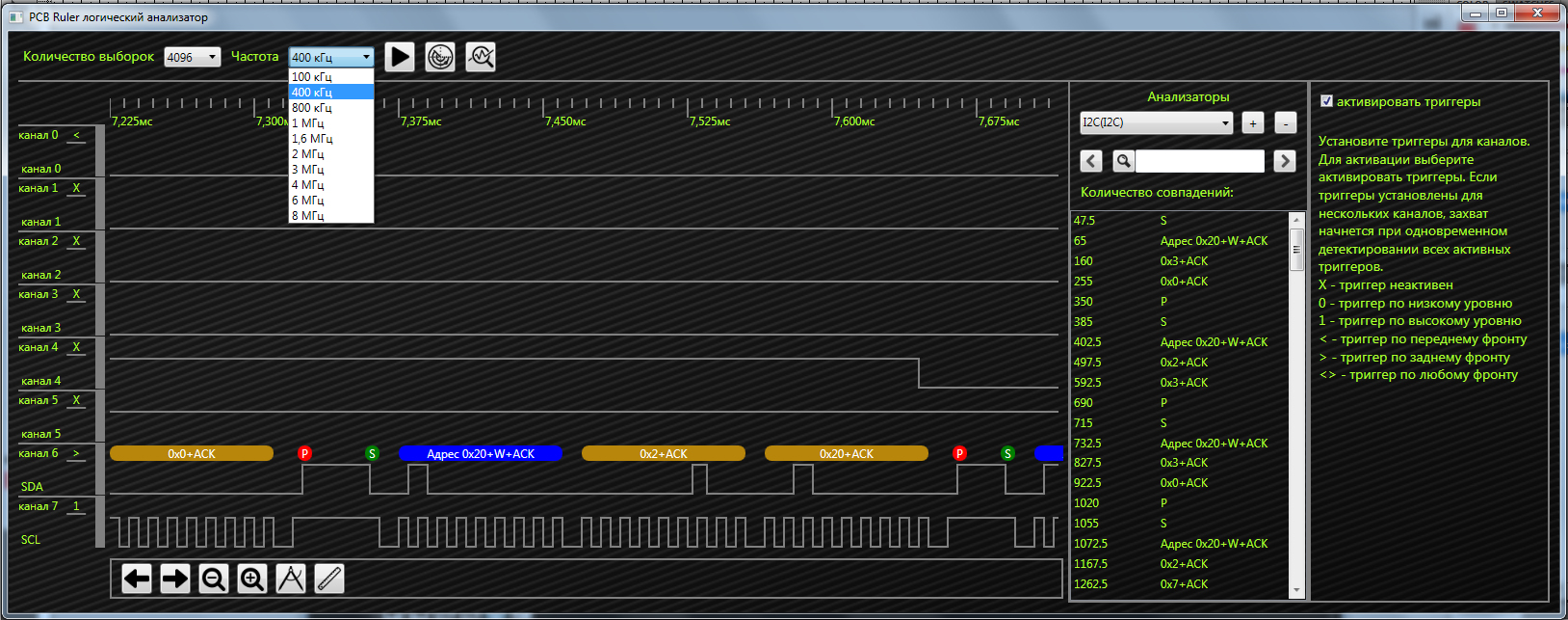
And if you stick to the serial I2C interface and activate the analyzer, all I2C components will be automatically tinted and labeled in an easy-to-analyze form.
The operation of the logic analyzer begins with clicking on the “Start capture” button. Then the following happens:
1) The capture parameters are transmitted to the device.
2.a) If the trigger is not set, the capture of the signal begins immediately after receiving the capture parameters.
2.b) If the trigger is set, the device analyzes the input signal without performing a capture. The signal capture begins after the detection of the conditions specified by the trigger.
3) The capture buffer is filled in accordance with the specified number of samples.
4) The device transmits data to the PC.
5) The software processes and displays the data received.
The trigger can be installed on one or more channels. If the triggers are specified for several channels, the capture of the signal begins with the simultaneous occurrence of all the conditions specified by the set triggers, i.e. between triggers operates a logical connection "And".
You can change the name and color of each channel. The signal display area can be scrolled or scaled.
Using the tool "Measurement" you can measure the duration of the selected area, period, frequency, pulse duration, count the number of fronts.
The Ruler tool draws a vertical line covering the signals of all channels at a specified location with an indication of time. The “ruler” is convenient when evaluating the location of the fronts of different channels relative to each other and relative to the zero time mark.
In this video on a simple example, you can see how it all works:
In conclusion, I want to add that the shell is written in Visual Studio, the software for the microcontroller in IAR. In the near future I will present a 16+ channel logic analyzer with I2C, SPI, UART, I2S. Two microcontrollers are considered for construction: stm32f730, stm32f446.
Thank you all, use on health!
→ Download instructions, firmware and sketch.
→ Download IAR project
→ Download Visual Studio project
Here it should be noted that the logical analyzer is hardware & software for capturing a signal and its subsequent research, measurement, and analysis of interfaces.
The shell for the PC allows, after acquisition, to analyze the signals on all 8 channels, as well as
measure the frequency of the signals, the period and duration of the pulses. Calculate the number of fronts in the selected area, the duration of this area.
')
And if you stick to the serial I2C interface and activate the analyzer, all I2C components will be automatically tinted and labeled in an easy-to-analyze form.
The operation of the logic analyzer begins with clicking on the “Start capture” button. Then the following happens:
1) The capture parameters are transmitted to the device.
2.a) If the trigger is not set, the capture of the signal begins immediately after receiving the capture parameters.
2.b) If the trigger is set, the device analyzes the input signal without performing a capture. The signal capture begins after the detection of the conditions specified by the trigger.
3) The capture buffer is filled in accordance with the specified number of samples.
4) The device transmits data to the PC.
5) The software processes and displays the data received.
The trigger can be installed on one or more channels. If the triggers are specified for several channels, the capture of the signal begins with the simultaneous occurrence of all the conditions specified by the set triggers, i.e. between triggers operates a logical connection "And".
You can change the name and color of each channel. The signal display area can be scrolled or scaled.
Using the tool "Measurement" you can measure the duration of the selected area, period, frequency, pulse duration, count the number of fronts.
The Ruler tool draws a vertical line covering the signals of all channels at a specified location with an indication of time. The “ruler” is convenient when evaluating the location of the fronts of different channels relative to each other and relative to the zero time mark.
In this video on a simple example, you can see how it all works:
In conclusion, I want to add that the shell is written in Visual Studio, the software for the microcontroller in IAR. In the near future I will present a 16+ channel logic analyzer with I2C, SPI, UART, I2S. Two microcontrollers are considered for construction: stm32f730, stm32f446.
Thank you all, use on health!
→ Download instructions, firmware and sketch.
→ Download IAR project
→ Download Visual Studio project
Source: https://habr.com/ru/post/423313/
All Articles