Simulation of the Sagnac effect using geometric optics
One of the most high-tech elements of the modern aerospace and military industry are high-precision inertial navigation systems (INS). The task of such systems, built on the basis of accelerometers and optical gyroscopes, is to determine the angular velocity, the acceleration of a moving object, and the overall orientation of the object in three-dimensional space.
The specificity of ANN modeling lies in the fact that in the modeling area, there is often both a rectilinear and a rotational motion, which greatly affects the operation of these systems and, therefore, requires consideration. In our article, we briefly describe what the Sagnac effect is and how it can be based on devices based on it in the COMSOL Multiphysics ® package.
For easy navigation, here’s a short outline of the article at the beginning:
- What are optical gyros
- Specificity of rotation accounting in modeling
- Sagnac effect: theoretical foundations
- Sagnac interferometer model in COMSOL Multiphysics ®
- Conclusion
Optical gyros and Sagnac effect
Perhaps it is the classical Sagnac interferometer that best of all demonstrates the need for highly accurate recording of the non-inertial motion of the simulation domain.
The simplest Sagnac interferometer consists of the following components:
- Light source
- A beam splitter that directs the light of the source along two different paths and then combines them
- A set of mirrors (usually including two or three mirrors)
The beam splitter and mirrors form a triangular or rectangular path along which light travels in both directions. At this time, the navigation system itself (as well as the air or space ship in which it is installed) also rotates at a certain angular velocity. Observing the interference of light rays (due to the Sagnac effect) that propagate along these trajectories, one can determine the angular velocity of rotation of the system with very high accuracy.
Measuring small rotations is vital for determining and controlling the orientation of objects in modern defense and space industries. Currently, the most widespread ring laser and fiber-optic gyroscopes, the principle of which is also based on the Sagnac effect. Note that the ring laser gyro has high accuracy, is cheap and easy to maintain, because, unlike mechanical gyros, it does not contain rotating parts.
Simulation of light propagation in rotating optical components
How to calculate the path of propagation of light in a rotating system of mirrors, prisms and beam splitters? In order not to delve into the theory of relativity, suppose that the rotational speed is much less than the speed of light, but it is large enough so that we have to take into account the rotation. There are at least two approaches to solving the problem:
- Rewrite the equations for the propagation of light in a non-inertial reference system.
- Rotate the design in real time while spreading the rays
The difference between these approaches is that in one case the model is in a non-inertial frame of reference with a moving interferometer (option 1), or in a “laboratory” frame of reference fixed in space (option 2). Since the second option is much simpler to implement, we will use this approach to simulate the Sagnac interferometer.
The COMSOL Multiphysics ® package is quite effective for modeling devices with a moving or deforming structure (which include the Sagnac interferometer and a ring laser gyroscope) and allows you to integrate and jointly simulate various interdisciplinary physical processes within a single computational model.
The work of complex physico-technical systems often implies a change in the geometry of objects, their movement or rotation. In addition, a change in geometry may be required when solving optimization problems or when analyzing the sensitivity of a model to geometric dimensions. To correctly simulate the processes in these cases, it is necessary to take into account the corresponding geometric transformations in the calculation model. COMSOL Multiphysics ® allows you to solve such problems with the help of moving grids and changing the geometric model directly in the modeling process.
In this video review (in Russian) , we consider examples of tasks in which adjustment and use of variable geometry is necessary, and we also show the main tools and special interfaces of COMSOL Multiphysics ® for working with variable geometry using specific visual examples.
Analysis of deformable and moving structures is traditionally performed with special care, since it is used in various fields: in the analysis of thermal stress, the interaction of fluid with the structure, multi-phase flows, as well as in electroplating, piezoelectric devices and so on. In fact, for accurate ray tracing in a moving structure, it suffices to specify the angular velocity of the system, and then run a standard calculation based on geometric optics technologies .

Sagnac effect: theoretical foundations
Before turning to the description of the model implemented in the package, let's briefly examine what the Sagnac effect is.
Imagine that light propagates strictly along a circle (for example, along a fiber-optic cable) in two opposite directions, as illustrated in fig. 1. Ray launch point - . The dotted line shows the direction clockwise, and the bold solid line indicates the direction counterclockwise. Light rays in this setting will be opposed to each other, since they propagate around the circumference in opposite directions.
If the ring were motionless, then the ray trajectories would intersect twice: first at the opposite point of the circle, and then at the starting point . Now imagine that the ring rotates counterclockwise around its center with a certain angular velocity. If we follow the movement point during the propagation of light, we will see that the beam propagating clockwise will return to it when it is already in a new position, . When to the point the beam propagating counterclockwise returns, it moves further and is in the position . is at a greater distance from than Because the circle also rotates counterclockwise.

Fig.1. Spread light clockwise and counterclockwise along the edge of the rotating circle.
It is obvious that the illustration in Figure 1 is significantly scaled for clarity, and in reality the distance between points is 10 billion times smaller. However, even in this case, the difference in the optical path traveled leads to a phase shift and, accordingly, interference.
Without going into theoretical calculations (but if they are interesting, we recommend the following classic work Post, Evert J. “Sagnac effect”, Reviews of Modern Physics, 39, no. 2, p. 475, 1967 ), the final relationship between the angular velocity and the difference in the optical path can be expressed as:
Where - the area of the circle in question, and - the speed of light.
In general, the Sagnac effect is even more general than the example described above. The propagation path of two opposing rays can be of any shape, but the delay between them will always be proportional to the size of the area, which is limited by the contour in which the rays propagate. In addition, this effect is also observed in cases when the center of rotation does not coincide with the center of the contour.
Test model of the Sagnac interferometer based on optical ray tracing
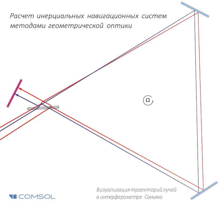
To test how COMSOL Multiphysics ® will calculate and, therefore, the sensitivity of the device, we consider the test design of the Sagnac interferometer, in which light propagates not around the circumference, but around the perimeter of the triangle, at the vertices of which are two mirrors and a beam splitter (Fig. 2).

Fig.2. Scheme of the Sagnac interferometer.
The original beam passes through the beam splitter, resulting in the formation of two beams of the same intensity. At the moment of leaving the beam splitter, they are at the same point and have the same phase. As the system of mirrors rotates, by the time when the rays return to the beam splitter, their optical paths (and, therefore, the phases) are different from each other.
In practice, instead of small values systems often detect a frequency shift (or beat frequency) :
Here - the effective length of the contour along which the rays propagate, and - their frequency. note that determined directly as part of the calculation.
The process of numerical ray tracing can be easily automated, for example, for parametric analysis. In fig. 3 shows the results of a parametric analysis in a wide range of angular velocities - from relatively small to very large.
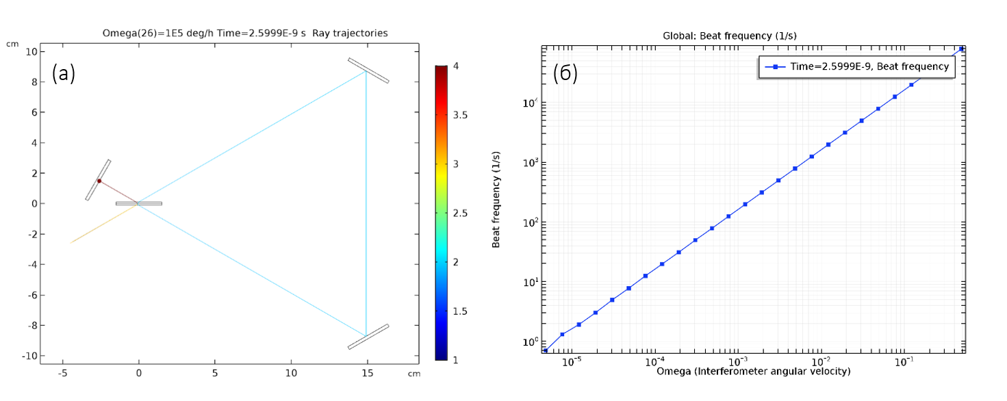
Fig.3. (a) The ray trajectories in the test interferometer. The discrepancies in the trajectories of the two beams are so insignificant that they are not noticeable even on a close-up. (B) The dependence of the beat frequency on the angular frequency of rotation of the system.
The corresponding beat frequency is perfectly consistent with the theoretical values. By changing the distance between the mirrors, it can be shown that the slope of this line is proportional to the area of the triangular region enclosed between oncoming beams.
Looking to the future or the practical application of numerical modeling of optical gyroscopes
The above results demonstrate that by tracing the rays in a rotating geometry (frame) using the described technique, it is possible to calculate with high accuracy the sensitivity of devices based on the Sagnac effect, if the rotation speed is small compared to the speed of light (i.e., without relativistic effects). Thus, thanks to this new model , modeling specialists and engineers working with angular orientation systems will now have a ready-made working pattern for studying the Sagnac effect, which underlies the operation of ring laser gyroscopes.
The attentive reader will probably ask a question about the need for such a numerical simulation, given that the Sagnac effect is described quite accurately by the above formula. It should be borne in mind that real ANNs are much more complicated than the simplest setup with a beam splitter and two mirrors, discussed above. Such systems are installed together with other sensitive devices in a confined space; an additional frame is required that ensures the immobility of the optical components relative to each other. In addition, ANNs often work in corrosive environments, and they are subject to mechanical stresses, temperature, and electromagnetic fields. These factors influence the behavior and sensitivity of the gyroscope, which requires more detailed and careful consideration, and cannot be described with the same simple formula.
Thus, the presented ray tracing in the Sagnac interferometer or ring laser gyroscope will be only the first step in the high-precision and complex multiphysical analysis of large optical systems. COMSOL Multiphysics ® allows you to trace the rays in the most realistic conditions, in particular with regard to heating and thermal deformation of optical components, which will open up new opportunities for better understanding and assessing the sensitivity and accuracy of complex inertial navigation systems.
The Ray Optics module of the COMSOL Multiphysics ® package provides extensive functionality for such calculations. In this case, the trajectories of such rays can be calculated over large distances with minimal computational cost , since there is no need to express the wavelength using a finite element mesh. Examples of the use of COMSOL Multiphysics ® in this area include modeling of laser resonators , lens systems, optical Bragg filters, interferometers, spectrographs , monochromators, etc.
In this video review (in Russian) we will talk about all the key features and benefits of this approach and module, including the possibility of combining with full-wave calculations, solving related thermal and mechanical problems and advanced post-processing tools, including by analyzing monochromatic aberrations.
Additional Information
This material is based on the following articles:
- C.Boucher. Understanding the Sagnac effect through ray optics simulation , Laser Focus World, August 2018
- Simulation of a Sagnac interferometer and a ring laser gyro using geometric optics , COMSOL corporate blog
For a more detailed acquaintance with the described techniques and examples, you can request a free full-featured demo version of COMSOL Multiphysics ® in the comments or via the link .
And we invite everyone on November 1 to the main event for current and future COMSOL users - COMSOL Day in Moscow .
- Free in the center of Moscow we talk all day about modeling in COMSOL
- Many active users of the package share experience and knowledge in one place.
- COMSOL engineers answer tricky questions
- Invited reports from leading high-tech and innovative organizations in Russia
- The program of 4 mini-courses: Mechanics, Electrical Engineering, Inverse Problems and Automation
- Coffee, cookies and multiphysics
')
Source: https://habr.com/ru/post/423283/
All Articles