How I developed the Russian tablet
Good day, friends!
In this article, there will be no Arduino, Raspberry, Olimex, transferring the insides of a tablet into your “custom” case made of cardboard and patch, etc. Only harsh engineering, only hardcore ...
I don’t know if I’ve chosen the title too loud for the article, but it seems like everything is fair: the Russian development, the tablet form factor, although it looks like a smiling smiley brick.
')
For my readers, I decided to sketch out a plan of the article so that you can easily navigate it and skip unnecessary points, but if you are going to write a comment, please read everything “so that it does not hurt painfully for years aimlessly ... (c)”.
As I wrote earlier in my articles, I am very attracted to the topic of displaying images on a matrix, and everything connected with it. Now you will not surprise anyone with scalers for matrixes, in the form of small boards for $ 10- $ 15, of which you can easily make / repair a monitor or TV, but with them I already played enough and I want something new.
The idea to make something similar to a tablet was born a long time ago, and I constantly nurtured it, pondering how to realize it with less effort and expense with greater profit. Of course, I don’t need the tablet itself, you can buy it for reasonable money if necessary or as a last resort to make a plywood case for Raspberry, but why do I need a Raspberry (and you can even buy a case ready to buy for it)? The implementation on its hardware with full development was interesting, but it needs money, and above all, time, which is always not enough (or in your day more than 24 hours?).
Two events served as an impetus for implementation, the first was that suddenly there appeared several unnecessary matrices from 7 to 10 inches, which oh how attracted me. Some of them are RGB, but also among them was the LVDS matrix and the built-in backlight driver and USB capacitive touch. The second is that there is a weak need for a compact reference for debugging software under IMX6, in which there would be almost everything and some more. Of course, it was easier to throw out the matrices, and take a ready reference from the shelf, but it’s not so simple, we use a certain set of peripherals (codecs, physics, charge controllers, etc.) that need to be debugged for the new functionality, and also wanted to experience something new (and the matrices are very attractive). Is it worth it to spend a month of their free evenings, you ask? Of course it is!
With these thoughts and a box of matrices, I began to develop. I knew that I could allocate very little time and at the same time it was not clear whether it would reach the second iteration.
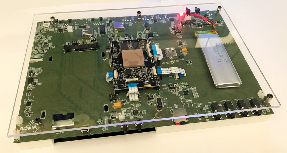
Fig.1. Photo "tablet" from the PCB.
To avoid unnecessary questions, I will try to anticipate some of them and immediately answer them.
2.1 Isn't it easier to buy a tablet?
- Easier, but less interesting.
2.2 How much does it cost and how much will it cost for a game?
- It is expensive, but our company took all the costs for the implementation of my little whim. No party is planned, done, so to speak, for yourself.
2.3 Where is the case? Why did not print it on the printer, not cut out of plywood, not made of clay (and so on).
- Now I have put everything together, and, in principle, it is possible to come up with something about the corps, but so far there is neither time nor desire. If it still reaches the second iteration of the board, when it will be possible to reduce the thickness, then in plans to make the case with a thin polished metal sheet from the bottom for heat removal.
2.4 Why not take a smaller / larger / thinner display?
- The display went for free, and the gift horse is known ...
2.5 Why did you install such a codec / feeder / battery / physics, etc.
- The chipset is limited to our warehouse and I wanted to buy as few components as possible, so I tried to use what I had.
This list is almost endless and you can extend it in the comments, but I will end there.
TK was only in the head, and it expanded as new sheets of the scheme were added to the altium. Of course, I wanted to squeeze everything I could out of the processor. At the first stage, and possibly at the last, it was decided to do everything on our module, since its board is 8 layers, and for the motherboard I will need no more than 4.
Interfaces:
3.1 LVDS - one channel for a 10-inch matrix + capacitive touch.
3.2 Ethernet - 1000/100/10 (for it to be).
3.3 Audio codec with multiple channels for input and output + built-in speakers and a microphone.
3.4 HDMI - standard monitor connector.
3.5 SATA - connect an external SSD drive.
3.6 Camera - one, and preferably two + flash.
3.7 E-Ink - a small display for displaying notifications, time, battery charge, networks, etc.
3.8 GPS - any module for location tracking.
3.9 CAN - differential, for connecting external devices.
3.10 SD card - debugging and software download. Data storage.
3.11 WiFi / BT / 4G - on USB inside the case (below I will explain why this is so).
3.12 USB - at least 5pcs + OTG + console.
3.13 Accelerometer - to flip the screen.
3.14 RTC - a separate chip for storing time when the device is completely de-energized.
3.15 NFC reader to play with.
3.16 Control buttons - on / off / volume / reset.
3.17 Battery - 3.7V, 4-6A.
3.18 Power supply 5-18V.
3.19 Linux OS.
That's all that I wanted. Below I will give explanations on some contradictory points why this is so.
It is fair to say why all the same on the module, and not immediately on the 8-layer board. It is more correct to transfer everything to one board only after debugging all the peripherals, if it is at all necessary. One iteration of the board (4-6pcs) on eight layers (60mmX40mm) costs about 50TR + components - this is pretty decent, so it's more correct on the layout. Prots on the 4-core module, each of them at 1 GHz.
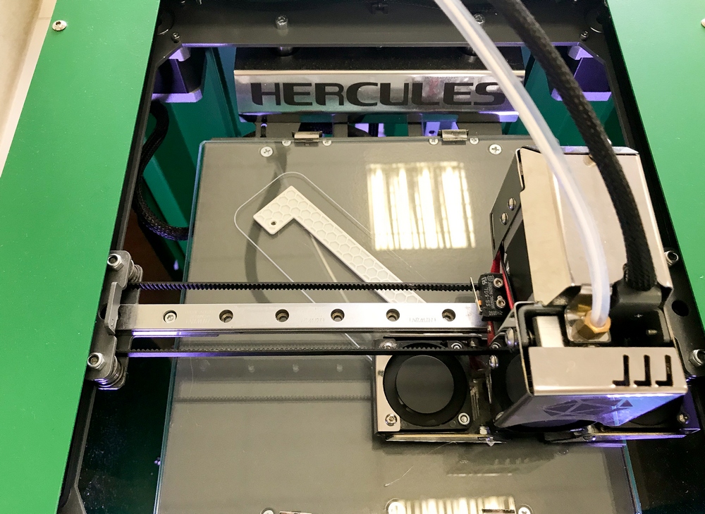
Fig.2. Printing body parts
The first thing I thought about was a lot of wireless interfaces. There should be several of them, and they should be on board. With GPS, everything was decided by itself, I have repeatedly used the SIM33 module with a built-in antenna, it works fine, though not cheap, it had a UART at the output and I already drew a footprint for it).
Wi-Fi / BT could also be implemented as a module on the board, since there are a lot of them, but for now let us postpone this question. 4G modems come in various form factors and modules on the connector and on the solder board and USB. Software is lifted by Maxim (our programmer), who is still an enthusiast and he offered to install several USB on the board in order to stick Wi-Fi / BT sticks (which we have repeatedly used), as well as try to raise the USB 4G modem, for example Yota or something like (what happens). In this case, we also have calls. So it was decided to do.
Inside the board are 3 USB, a) Wi-Fi / BT, b) 4G modem, c) a module for a wireless keyboard / mouse. IMX6 has only two USB onboard, with one of them being OTG and may be needed for debugging, so it is displayed on the back panel in the form of a miniUSB connector. The second USB goes to the TUSB2077 hub from TI, which has 7 ports at the output, for which Maxim has already raised the driver before, so I used it. The back panel comes out 3 USB for connecting external devices. Another microUSB on the back panel for outputting a console UART chip for debugging (via CP2102 on the main board).
E-Ink display chose tricolor (gray / black / red), one of the most common for Arduino. It is not purchased yet, as it is not yet up to it. It seemed to me a rather interesting decision not to turn on the screen, but to display some information on a small display and update it occasionally. Also really want to play with E-Ink.

Fig.3. Photo display E-Ink.
Our IMX6 module has a connector (MIPI_CSI aside, there come three supply voltages, I2C, reset, PWM, etc.) for connecting the OV5640-M4320 camera, even two. So one camera has earned (directly to the module connector), but with two questions. The cable of such a camera is usually from 3cm to 12cm. On the board, I spread the MIPI_CSI in the right places of the board, but have not yet verified. Something tells me that this interface will not work for 15-20cm, or it will lag.

Fig.4. Photo camera OV5640-M4320.
These cameras are 5 megapixel with built-in autofocus.
On the back of the device, it is planned to make a flash for the camera, for this I made a portable scarf (just on the board you can see a hole from this scarf, I spread it directly to the main one, so as not to order separately) on the cable with the LED (MP-3030-1100- 56-95) and put the ADP1653 flash driver on the main board. I never thought that the flash should be quite clearly synchronized with the frame (although this is logical), this driver can do this on I2C, which most likely will not work on an external interrupt. We'll see when the time comes, how it happened.
The IMX6 has a built-in RTC, which proved to be not very good in terms of power consumption, or I didn’t see anything, so I decided to install an external PCF8523 chip, which has quite a working driver for Linux. The time synchronization function itself is not particularly interesting to me, since it can be done over networks, but to wake up by an event is necessary. I put this development miracle on the bedside table and wait for the alarm clock to work, just like the Nokia 3310 has risen from the off state.
When the external voltage is applied (in the off state of the device), the following are powered: the charge controller BQ25895, RTC and the supervisor STM6601, which controls the secondary power supply at the touch of a button or soft (if we want to not shut down the power but finish the OS correctly, then de-energize) ). As a result, the power turned out to be a rather interesting design, I have not had time to take measurements of consumption in different modes, but with hardware shutdown, all the peripherals should turn out pretty well. As a result, in the “tablet” there is no “duty room” as such, STM6601 and PCF8523 are powered directly from a Li-Ion battery (3.7V) + to the RTC battery 2016 or 2032 (universal holder). The 2.3A battery is now connected (it is about to arrive at 6A), in the desktop display mode the charge holds for about 30 minutes - this is of course very small, but let's see what happens with a full battery.
Accelerometer LIS331 is only needed to track the position to flip the display, so put what is already yuzal. A good microcircuit with I2C / SPI interfaces and interraptes.
A full-fledged SATA connector was put on the type of "I want, and why not)." I understand that eMMC / NAND is used in tablets, but since there is an interface, why not use it? Since in this variant there is enough space for SSD 2.5 ”- let it be worth it.
Maxim insisted on installing NFC. I still do not know what it will do with this interface, but what can you not do for the sake of the programmer’s vagaries? I really wouldn’t really like him to try to pay at the grocery store, putting this device to a wireless reader.
CAN is sometimes needed in our development, so I put the TJA1040T physics, we already have a driver for it, we can work with it, we even connected it to our cars and watched the tables. Fun thing.
The codec is again ADAU1761, to feel all the delights of working with sound. First of all, it was he who was thinking (and not SGTL5000, which is also nothing) for debugging firmware for the built-in DSP (SigmaStudio). Therefore, two connectors for speakers (via an amplifier) go to the back wall, to the side connector for an internal microphone, as well as several (remaining) inputs / outputs for 3.5mm jacks on the front panel.
The HDMI output seemed to me very convenient, and on a standard connector. Before that, I put microHDMI in development, but it seems to me that this makes sense only when the dimensions are limited.
So that all this somehow lived and did not consume 100,500 amps at the same time, I put the TCA6424 chip on the board - this is a GPIO expander, which in this case serves as a switch for the periphery. SATA, display (its power and backlight), sound (codec and amplifier), accelerometer, GPS and everything else is connected to the power supply via transistor switches TPS27081 is a dual transistor switch that can break power to 8V and up to 3A. So, in addition to any software sleep modes, you can hardware disable interfaces. The extender is controlled by I2C, so you can write an on-screen program that can turn everything off.
Now why all the same Linux. According to Maxim, it's much easier to run everything under Android, but as practice has shown, we have more projects under Linux. Yes, the fuss will probably be more, but it seems to me that with Xubuntu (it is now on the device), the “tablet” acquires some originality and is more suitable for our tasks.
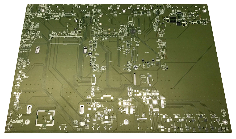
Fig.5. Printed circuit board.
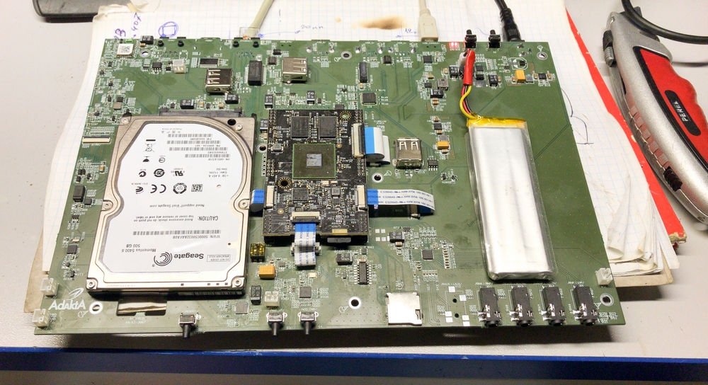
Fig.6. Board with installed components.
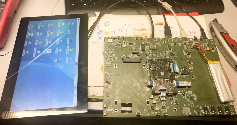
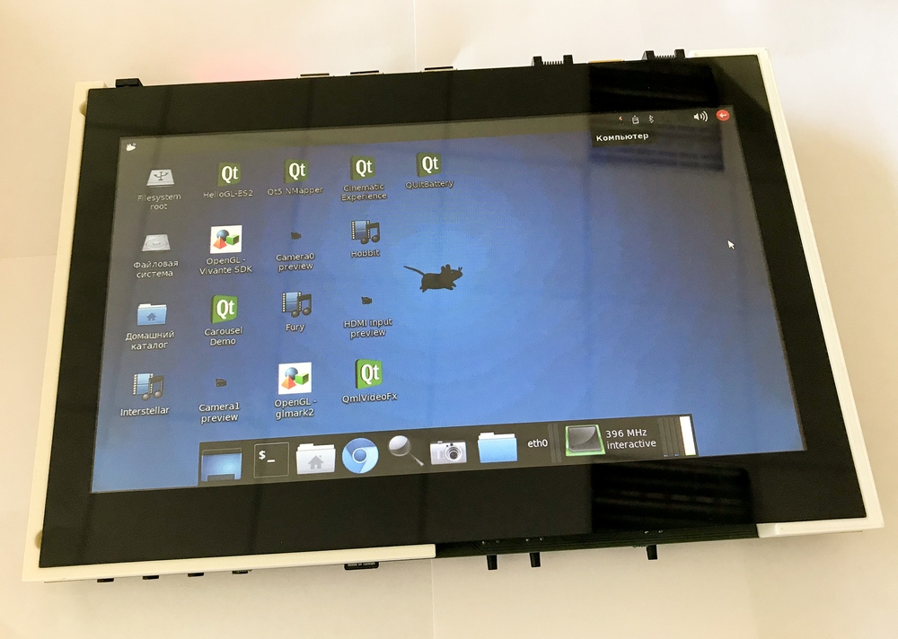
Fig.7. First start.
First of all, of course, I want to reduce the size of the thickness. This can be achieved in only one way - transferring the processor to the board and changing its geometry. The refusal of SATA will be justified, it will be more correct to put the eMMC on 64 / 128Gb (at the moment it costs 8Gb). The battery should not be on the board, but next to it, well, in general, we all know the location of the elements inside the tablets, everything has already been invented before us. I already wrote about the case above, I would like a plate for cooling, so far I have not really thought about how to implement the remaining elements.
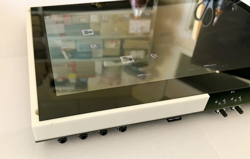
Fig.8. In the case. Audio inputs / outputs.

Fig.9. Assembled device.
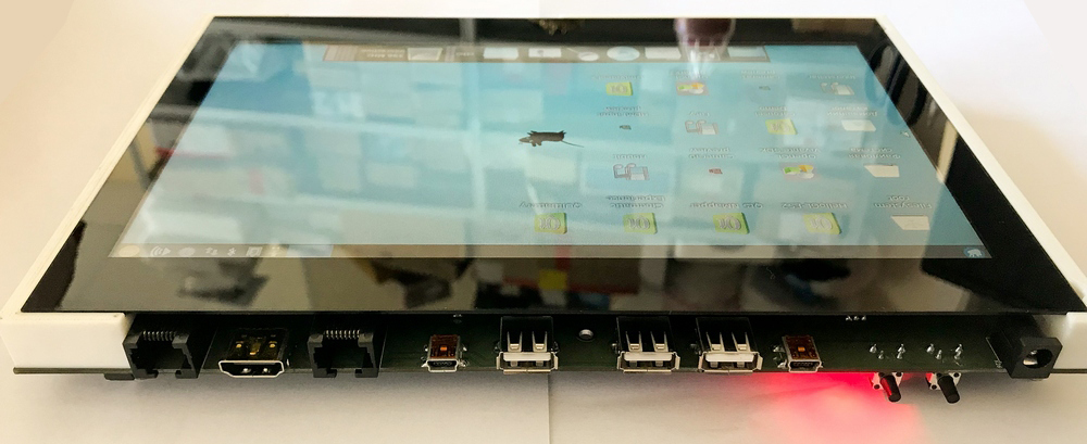
Fig.10. Rear panel.
Since the project is being developed (now software) in its free time, not everything has been managed to be raised. Maxim saws something and the “tablet” gradually comes to life, but the final is not yet visible.
In my opinion, the device turned out quite viable, for the tasks described above. I installed the VLC player and now you can watch movies on a small screen)). If, in essence, my idea was realized almost completely (first iteration), not counting the case. Having sealed the module onto the board, you can get a total thickness of no more than 23mm - this is of course harsh for current foreign electronics, but for the prototype it is quite acceptable.
PS: a link to the source code github.com/boundarydevices/linux-imx6/commits/boundary-imx_4.9.x_1.0.0_ga
All success in your endeavors!
In this article, there will be no Arduino, Raspberry, Olimex, transferring the insides of a tablet into your “custom” case made of cardboard and patch, etc. Only harsh engineering, only hardcore ...
I don’t know if I’ve chosen the title too loud for the article, but it seems like everything is fair: the Russian development, the tablet form factor, although it looks like a smiling smiley brick.
')
For my readers, I decided to sketch out a plan of the article so that you can easily navigate it and skip unnecessary points, but if you are going to write a comment, please read everything “so that it does not hurt painfully for years aimlessly ... (c)”.
- Introduction Idea.
- Answers on questions.
- What I wanted to get at the exit.
- Description of iron.
- Perspectives. If it will be necessary.
- Findings. Summarizing.
1. Introduction. Idea.
As I wrote earlier in my articles, I am very attracted to the topic of displaying images on a matrix, and everything connected with it. Now you will not surprise anyone with scalers for matrixes, in the form of small boards for $ 10- $ 15, of which you can easily make / repair a monitor or TV, but with them I already played enough and I want something new.
The idea to make something similar to a tablet was born a long time ago, and I constantly nurtured it, pondering how to realize it with less effort and expense with greater profit. Of course, I don’t need the tablet itself, you can buy it for reasonable money if necessary or as a last resort to make a plywood case for Raspberry, but why do I need a Raspberry (and you can even buy a case ready to buy for it)? The implementation on its hardware with full development was interesting, but it needs money, and above all, time, which is always not enough (or in your day more than 24 hours?).
Two events served as an impetus for implementation, the first was that suddenly there appeared several unnecessary matrices from 7 to 10 inches, which oh how attracted me. Some of them are RGB, but also among them was the LVDS matrix and the built-in backlight driver and USB capacitive touch. The second is that there is a weak need for a compact reference for debugging software under IMX6, in which there would be almost everything and some more. Of course, it was easier to throw out the matrices, and take a ready reference from the shelf, but it’s not so simple, we use a certain set of peripherals (codecs, physics, charge controllers, etc.) that need to be debugged for the new functionality, and also wanted to experience something new (and the matrices are very attractive). Is it worth it to spend a month of their free evenings, you ask? Of course it is!
With these thoughts and a box of matrices, I began to develop. I knew that I could allocate very little time and at the same time it was not clear whether it would reach the second iteration.
Fig.1. Photo "tablet" from the PCB.
2. Answers to questions
To avoid unnecessary questions, I will try to anticipate some of them and immediately answer them.
2.1 Isn't it easier to buy a tablet?
- Easier, but less interesting.
2.2 How much does it cost and how much will it cost for a game?
- It is expensive, but our company took all the costs for the implementation of my little whim. No party is planned, done, so to speak, for yourself.
2.3 Where is the case? Why did not print it on the printer, not cut out of plywood, not made of clay (and so on).
- Now I have put everything together, and, in principle, it is possible to come up with something about the corps, but so far there is neither time nor desire. If it still reaches the second iteration of the board, when it will be possible to reduce the thickness, then in plans to make the case with a thin polished metal sheet from the bottom for heat removal.
2.4 Why not take a smaller / larger / thinner display?
- The display went for free, and the gift horse is known ...
2.5 Why did you install such a codec / feeder / battery / physics, etc.
- The chipset is limited to our warehouse and I wanted to buy as few components as possible, so I tried to use what I had.
This list is almost endless and you can extend it in the comments, but I will end there.
3. What I wanted to get at the exit.
TK was only in the head, and it expanded as new sheets of the scheme were added to the altium. Of course, I wanted to squeeze everything I could out of the processor. At the first stage, and possibly at the last, it was decided to do everything on our module, since its board is 8 layers, and for the motherboard I will need no more than 4.
Interfaces:
3.1 LVDS - one channel for a 10-inch matrix + capacitive touch.
3.2 Ethernet - 1000/100/10 (for it to be).
3.3 Audio codec with multiple channels for input and output + built-in speakers and a microphone.
3.4 HDMI - standard monitor connector.
3.5 SATA - connect an external SSD drive.
3.6 Camera - one, and preferably two + flash.
3.7 E-Ink - a small display for displaying notifications, time, battery charge, networks, etc.
3.8 GPS - any module for location tracking.
3.9 CAN - differential, for connecting external devices.
3.10 SD card - debugging and software download. Data storage.
3.11 WiFi / BT / 4G - on USB inside the case (below I will explain why this is so).
3.12 USB - at least 5pcs + OTG + console.
3.13 Accelerometer - to flip the screen.
3.14 RTC - a separate chip for storing time when the device is completely de-energized.
3.15 NFC reader to play with.
3.16 Control buttons - on / off / volume / reset.
3.17 Battery - 3.7V, 4-6A.
3.18 Power supply 5-18V.
3.19 Linux OS.
That's all that I wanted. Below I will give explanations on some contradictory points why this is so.
4. Description of iron
It is fair to say why all the same on the module, and not immediately on the 8-layer board. It is more correct to transfer everything to one board only after debugging all the peripherals, if it is at all necessary. One iteration of the board (4-6pcs) on eight layers (60mmX40mm) costs about 50TR + components - this is pretty decent, so it's more correct on the layout. Prots on the 4-core module, each of them at 1 GHz.
Fig.2. Printing body parts
The first thing I thought about was a lot of wireless interfaces. There should be several of them, and they should be on board. With GPS, everything was decided by itself, I have repeatedly used the SIM33 module with a built-in antenna, it works fine, though not cheap, it had a UART at the output and I already drew a footprint for it).
Wi-Fi / BT could also be implemented as a module on the board, since there are a lot of them, but for now let us postpone this question. 4G modems come in various form factors and modules on the connector and on the solder board and USB. Software is lifted by Maxim (our programmer), who is still an enthusiast and he offered to install several USB on the board in order to stick Wi-Fi / BT sticks (which we have repeatedly used), as well as try to raise the USB 4G modem, for example Yota or something like (what happens). In this case, we also have calls. So it was decided to do.
Inside the board are 3 USB, a) Wi-Fi / BT, b) 4G modem, c) a module for a wireless keyboard / mouse. IMX6 has only two USB onboard, with one of them being OTG and may be needed for debugging, so it is displayed on the back panel in the form of a miniUSB connector. The second USB goes to the TUSB2077 hub from TI, which has 7 ports at the output, for which Maxim has already raised the driver before, so I used it. The back panel comes out 3 USB for connecting external devices. Another microUSB on the back panel for outputting a console UART chip for debugging (via CP2102 on the main board).
E-Ink display chose tricolor (gray / black / red), one of the most common for Arduino. It is not purchased yet, as it is not yet up to it. It seemed to me a rather interesting decision not to turn on the screen, but to display some information on a small display and update it occasionally. Also really want to play with E-Ink.
Fig.3. Photo display E-Ink.
Our IMX6 module has a connector (MIPI_CSI aside, there come three supply voltages, I2C, reset, PWM, etc.) for connecting the OV5640-M4320 camera, even two. So one camera has earned (directly to the module connector), but with two questions. The cable of such a camera is usually from 3cm to 12cm. On the board, I spread the MIPI_CSI in the right places of the board, but have not yet verified. Something tells me that this interface will not work for 15-20cm, or it will lag.
Fig.4. Photo camera OV5640-M4320.
These cameras are 5 megapixel with built-in autofocus.
On the back of the device, it is planned to make a flash for the camera, for this I made a portable scarf (just on the board you can see a hole from this scarf, I spread it directly to the main one, so as not to order separately) on the cable with the LED (MP-3030-1100- 56-95) and put the ADP1653 flash driver on the main board. I never thought that the flash should be quite clearly synchronized with the frame (although this is logical), this driver can do this on I2C, which most likely will not work on an external interrupt. We'll see when the time comes, how it happened.
The IMX6 has a built-in RTC, which proved to be not very good in terms of power consumption, or I didn’t see anything, so I decided to install an external PCF8523 chip, which has quite a working driver for Linux. The time synchronization function itself is not particularly interesting to me, since it can be done over networks, but to wake up by an event is necessary. I put this development miracle on the bedside table and wait for the alarm clock to work, just like the Nokia 3310 has risen from the off state.
When the external voltage is applied (in the off state of the device), the following are powered: the charge controller BQ25895, RTC and the supervisor STM6601, which controls the secondary power supply at the touch of a button or soft (if we want to not shut down the power but finish the OS correctly, then de-energize) ). As a result, the power turned out to be a rather interesting design, I have not had time to take measurements of consumption in different modes, but with hardware shutdown, all the peripherals should turn out pretty well. As a result, in the “tablet” there is no “duty room” as such, STM6601 and PCF8523 are powered directly from a Li-Ion battery (3.7V) + to the RTC battery 2016 or 2032 (universal holder). The 2.3A battery is now connected (it is about to arrive at 6A), in the desktop display mode the charge holds for about 30 minutes - this is of course very small, but let's see what happens with a full battery.
Accelerometer LIS331 is only needed to track the position to flip the display, so put what is already yuzal. A good microcircuit with I2C / SPI interfaces and interraptes.
A full-fledged SATA connector was put on the type of "I want, and why not)." I understand that eMMC / NAND is used in tablets, but since there is an interface, why not use it? Since in this variant there is enough space for SSD 2.5 ”- let it be worth it.
Maxim insisted on installing NFC. I still do not know what it will do with this interface, but what can you not do for the sake of the programmer’s vagaries? I really wouldn’t really like him to try to pay at the grocery store, putting this device to a wireless reader.
CAN is sometimes needed in our development, so I put the TJA1040T physics, we already have a driver for it, we can work with it, we even connected it to our cars and watched the tables. Fun thing.
The codec is again ADAU1761, to feel all the delights of working with sound. First of all, it was he who was thinking (and not SGTL5000, which is also nothing) for debugging firmware for the built-in DSP (SigmaStudio). Therefore, two connectors for speakers (via an amplifier) go to the back wall, to the side connector for an internal microphone, as well as several (remaining) inputs / outputs for 3.5mm jacks on the front panel.
The HDMI output seemed to me very convenient, and on a standard connector. Before that, I put microHDMI in development, but it seems to me that this makes sense only when the dimensions are limited.
So that all this somehow lived and did not consume 100,500 amps at the same time, I put the TCA6424 chip on the board - this is a GPIO expander, which in this case serves as a switch for the periphery. SATA, display (its power and backlight), sound (codec and amplifier), accelerometer, GPS and everything else is connected to the power supply via transistor switches TPS27081 is a dual transistor switch that can break power to 8V and up to 3A. So, in addition to any software sleep modes, you can hardware disable interfaces. The extender is controlled by I2C, so you can write an on-screen program that can turn everything off.
Now why all the same Linux. According to Maxim, it's much easier to run everything under Android, but as practice has shown, we have more projects under Linux. Yes, the fuss will probably be more, but it seems to me that with Xubuntu (it is now on the device), the “tablet” acquires some originality and is more suitable for our tasks.
Fig.5. Printed circuit board.
Fig.6. Board with installed components.
Fig.7. First start.
5. Perspectives. If it will be necessary.
First of all, of course, I want to reduce the size of the thickness. This can be achieved in only one way - transferring the processor to the board and changing its geometry. The refusal of SATA will be justified, it will be more correct to put the eMMC on 64 / 128Gb (at the moment it costs 8Gb). The battery should not be on the board, but next to it, well, in general, we all know the location of the elements inside the tablets, everything has already been invented before us. I already wrote about the case above, I would like a plate for cooling, so far I have not really thought about how to implement the remaining elements.
Fig.8. In the case. Audio inputs / outputs.
Fig.9. Assembled device.
Fig.10. Rear panel.
6. Conclusions. Summarizing.
Since the project is being developed (now software) in its free time, not everything has been managed to be raised. Maxim saws something and the “tablet” gradually comes to life, but the final is not yet visible.
In my opinion, the device turned out quite viable, for the tasks described above. I installed the VLC player and now you can watch movies on a small screen)). If, in essence, my idea was realized almost completely (first iteration), not counting the case. Having sealed the module onto the board, you can get a total thickness of no more than 23mm - this is of course harsh for current foreign electronics, but for the prototype it is quite acceptable.
PS: a link to the source code github.com/boundarydevices/linux-imx6/commits/boundary-imx_4.9.x_1.0.0_ga
All success in your endeavors!
Source: https://habr.com/ru/post/423279/
All Articles