Domestic CAD-platform nanoCAD Plus 10: a universal complex for those who design
In the spring of 2018, our company (Nanosoft) released the nanoCAD Plus 10, a new version of the Russian CAD platform dedicated to the 10th anniversary of the company. Just think - 10 years, we create nanoCAD for the benefit of our users! What's new in the product? A few months ago, I answered this question as part of the YouTube broadcast, which was attended by 600 people. By itself, this presentation format was new for us, technically complicated, but, in my opinion, it turned out great - the presentation itself took one hour, and then I answered the listeners' questions for another 50 minutes. As a result, we received a unique video presentation, in which we tell in detail and clearly about product innovations. To date, the recording of the broadcast watched more than four and a half thousand people, who mostly put huskies. If you missed the broadcast, see the record - I recommend.
But in the process of preparing the presentation, I often found myself thinking that, talking about product innovations, I was missing something more - focusing only on innovations, cutting off the general positioning of the product. What has nanoCAD become in 10 years of development? How is it convenient and why should it be useful to our users? What are its key benefits? In general, in general, what is the nanoCAD platform? Therefore, I decided to write an article-review of our software package for those who are not ready to collect new items scattered across different versions, but want to get a complete picture of nanoCAD in one article. In fact, it will be a review of the modern Russian CAD solutions and potential directions for the development of CAD systems, as well as an answer to the question of where nanoCAD is moving as a product.
So, the Russian platform nanoCAD Plus in the eyes of the developer: what is it and for what?
')
Introduction, which is partly a look into the story
Having undertaken 10 years ago for the creation of a new computer-aided design (CAD) system, we, of course, did not reinvent the wheel - there were enough competing solutions, the design technologies had already become classical and mass. Moreover, new design methods began to emerge through 3D and an object-oriented approach that marketers turn into beautiful names - three-dimensional design, information modeling, BIM, additive design, “smart city”, etc., etc. Many CAD specialists predicted (and still predict) the speedy dying of classical design methods through drafting, and most of them did not believe in the success of yet another "classic electronic drawing board nanoCAD Plus" (and even now they do not believe it). How much I heard at that time ...
But everyone in our team had a clear feeling that, despite the fashion trends in design, despite the high competition, the task of creating a classic CAD system will be in demand in the coming years not only in our country, but throughout the world. What could be better than a good quality tool that works for the most intelligent decision-making system - a person? Actually, the past 10 years confirm that we were right then. And I think that the situation will not change for another 10-20 years ...
In addition, we already had some groundwork and experience of interaction with Russian (and not only) design organizations - we have been developing the Raster Arts software package since 1989 (can be translated as “raster art”, more details here: www.rasterarts.ru ), which were intended for processing scanned project documentation (first of all, drawings) and vectorization (translation of scan-copies into vector form). In fact, we gave a tool (Fig. 1), which allowed after the scanner to restore documents (clean from “garbage”, improve quality, eliminate distortions and distortions that paper introduced, etc.), and then translate them into a vector view , convenient for editing in classic CAD. This complex was based on two solutions:
- RasterDesk (can be translated as “raster tasks”) - a solution that was installed on the most popular vector editor at that time for the development of AutoCAD drawings and added editing tools for raster substrates;
- Spotlight (can be translated as “searchlight, light source”) is essentially RasterDesk, but based on our vector editor; was intended for jobs where AutoCAD was redundant and expensive.
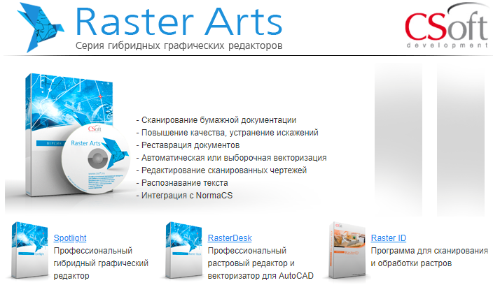
Fig. 1. The Raster Arts complex (“Raster Art”) became the prototype of the nanoCAD Plus CAD system
Actually, the nanoCAD Plus platform was the logical continuation of the development of the software product Spotlight, the foundations of which were laid back in 1989. By 2008, the Raster Arts complex was sold not only in Russia, but throughout the world (under the WiseImage brand), we gained experience both in the design and development of complex software systems, and in support of the DWG format and the vector editor AutoCAD, interaction with users, mass technical support in all types of languages and many other things. All prerequisites to make something new and useful!
And in 2008, from the CSoft Development group, the Nanosoft division was allocated to create a Russian CAD platform nanoCAD. Why "nano-"? Well, “micro-” is 10 to the power of -6, and we are somewhat less. Therefore, "nano-" (10 to the power of -9) ...
General view of the new CAD
What is nanoCAD? If to speak with marketing positioning words, “nanoCAD Plus is a domestic classic universal CAD platform”. In this phrase all key words:
- CAD - computer-aided design system, that is the main tool for designers.
- Classic - that is, using classical design methods: from primitives to a drawing (in exactly the same way as the drawing board was usually used).
- Universal - that is, not tied to any subject area: nanoCAD is equally suitable for designing engineering parts, floor plans, cuts / facades, spaceships and even a summer cottage.
- Domestic - the system is developed in Russia, and the Russian version is sharpened to the requirements of the Russian market.
- Finally, the word “platform” means that the functionality of nanoCAD can be expanded with applications, calculations, modules, honing the system for specialized tasks.
The main tasks that nanoCAD Plus solves are the development and release of working documentation (drawings) in any design groups and any subject area.
That is, nanoCAD Plus is a simple drawing board, albeit electronic?
In general, yes. But not everything is so simple ... In order to answer the question in the subtitle, it is necessary to understand the general structure of the CAD market.
The subtlety is that the task of developing and issuing documentation can be solved in different ways: someone just draws (a la paper-pencil-ruler-eraser), and someone tries to automate their work (ideally trying to bring it to the I speak to her, and the program draws everything herself "). These are the two extreme points between which all modern CAD and design technologies are located - both BIM-solutions, and three-dimensional modeling tools, and calculation programs, and ink-scans (Fig. 2). What's better? Oh, oh-oh, quite a few copies have already been broken in attempts to answer this question, and the end-to-end discussions are not visible ... In fact, this is the question “Which is better: a universal tool or a narrow tool?”
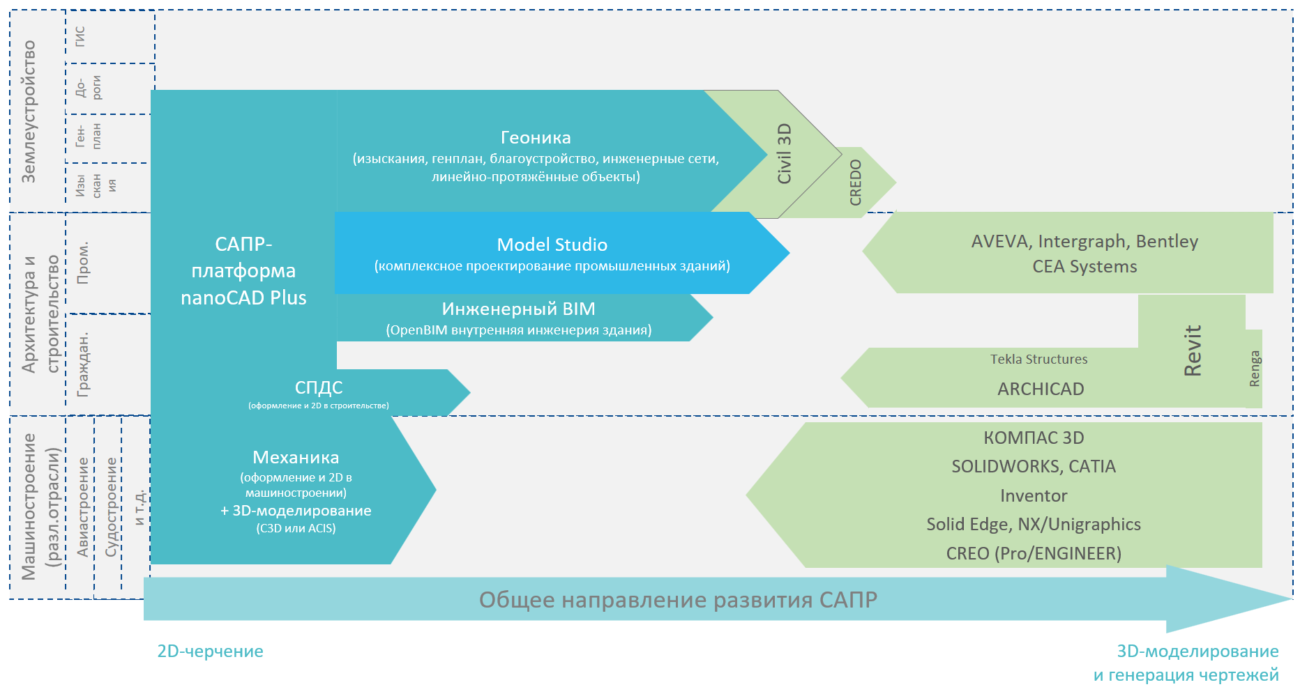
Fig. 2. The general scheme of development of design tools (clickable)
As shown in fig. 2 and as I said above, the nanoCAD Plus platform is evolving from the classic universal electronic drawing board (see video 1 below) - this is the principal positioning of the product at the moment. At the same time, in its basic form, nanoCAD Plus automates precisely drawing - segments-arc-hatching, work with layers, more convenient work with texts, callouts, tables, etc. (Fig. 3). In this sense, the electronic drawing board of the nanoCAD Plus is hundreds of times better than the classic paper drawing board, but it is not a big red button. It should be understood that by automating the routine with the help of nanoCAD Plus, the main work on the design is still performed by a person. It is the designer who, having thought over the design decision, makes different types of the same object - the top, side, left view, draws up dimensions, text explanations, etc. Nothing happens automatically! Something has changed in the design decision - all kinds, tables, calculations, reports need to be redone by hand ...
This positioning is opposed to the development schemes of other CAD solutions such as ARCHICAD, Revit, KOMPAS 3D, Renga, Inventor, etc., which go from a three-dimensional model to drawings. In such systems, the main focus is on three-dimensional modeling and laying links between intelligent objects tied to the subject area: for example, a window can be embedded in a wall, have a height-width, a geometry (two- or single-door), a manufacturer and a bunch of other parameters. Accordingly, such programs automatically draw from these data either a three-dimensional model of a brick wall with a double-wing window with a window, or their 2D-drawings (floor plan, facade, section, node, etc.), or draw it all into a table-specification. Once again according to the words: the program is drawing! This is a fundamental positioning of this type of CAD. Changes in the data (for example, increased the width of the window) will lead to automatic change of all related species, as the program instantly draws new types. In fact, such programs promise to replace the work of the draftsman in favor of modeling the situation with a designer and automatic drawing of views with a program. Do you feel a fundamental difference in relation to nanoCAD and classic CAD systems?
Video 1. nanoCAD Plus is a domestic classic universal CAD platform containing all the necessary basic design tools.
I am often asked, what is the nanoCAD better than such systems? This problem should be baffled, because you cannot answer unambiguously. On the one hand, three-dimensional modeling systems are more promising - and it’s hard to argue with that. And there are many users who, with the help of such solutions, achieve automation and other good results. But, on the other hand, none of them is universal. Look at the pic. 2 attentively - I divided the specialized CAD systems into three areas: engineering, architecture, land management. In reality, the CAD classification is much broader - only mechanical engineering can be further divided into 5-6 specializations: aircraft manufacturing, shipbuilding, machine-tool manufacturing, the automotive industry, non-standard equipment, etc. But even within the framework of a highly specialized field, such intellectual programs are limited by their capabilities. If the program does not include industry-specific algorithms, then the level of automation catastrophically drops, throwing the user into the world of universal volumetric modeling or simply classical drafting. For example, we seem to be able to simulate the volume of a building with wall decoration, but already the engineering part (electrician, pipeline design, water / sewage) in this program is simply drawn by three-dimensional cylinder-cylinders or ordinary 2D primitives on the prepared views. Or a machine-building tool can make mechanisms and engines, but it is completely inapplicable for designing ships, since the level of geometry is more complicated in analysis and design. I'm not talking about the fact that some try using a machine-building tool to make three-dimensional models of the earth (and sellers / marketers actively encourage them in this: “yes, you can”) and wonder why they do not achieve success. Therefore, not everything is so simple ...
What features can be distinguished from three-dimensional automated CAD systems?
- The main thing is sharpening for a specific task. If the task is not solved completely (and it is often not solved), users are forced to use a universal electronic drawing board.
- Another facet of sharpening is incomplete task coverage. There is a huge number of areas in the design that are not closed by any solutions - to develop a specialized tool for them is very expensive, and the number of users will be minimal. And therefore, a universal drawing board is used here (well, do not draw on paper, since there is no specialized tool!).
- The complexity of the study - three-dimensional intellectual products require higher qualifications of designers, more in-depth study and immersion in particular software. Not everyone can afford to polish their knowledge of the tool for years. Especially if this knowledge is not additionally paid for (for example, in the regions).
- And finally, the high price - it consists not only of the cost of implementation and the price of a specialist, the very expensive solutions are very expensive. Innovative products often allow to bring design organizations to a new level of design, but innovative development in its essence is not aimed at mass use - this is only for those who can afford to be ahead. Therefore, the prices of such software products start from 500 thousand rubles for one workplace, and in the upper bar are practically unlimited.
It is these reasons that lead to the popularity of classic design technologies among the mass user. There are not very many companies all over the world that have completely switched to three-dimensional modeling - according to my estimates, no more than 20-30%. Most often, such organizations are either narrowly focused on a project specialty (for example, a purely architectural bureau), or are engaged in conceptual design of new objects, leaving the details and routine to contracting organizations. In other cases (and the rest, the vast majority), design organizations set up a symbiosis between classical design and three-dimensional modeling (in various proportions): for example, in one department they create a new mechanism, which is first worked out and displayed in 3D, collisions are analyzed in volume at the stage of invention, but not of a prototype, and then given to detailed study for mass production in other departments ...
Pay attention to the main point of this section: despite the active advertising of modern design methods, their obvious advantages provided by automation, intelligence, despite the active investment in these areas by design organizations, no one can completely abandon 2D CAD! And, I think, this situation will not change for a very long time, and the nanoCAD Plus platform has excellent positioning for mass use.
Can nanoCAD Plus become a specialized design tool?
Yes, of course ... Without a doubt, we want to create more convenient and intelligent tools aimed at innovation. And here comes the principle of expanding the functionality of the nanoCAD platform through specialized solutions (applications). What is the principle? Will explain…
Under the nanoCAD Plus platform, you can write an application of any complexity that, using the nanoCAD graphics capabilities, support for the world's most popular CAD format (DWG), import and export of other formats and modern programming languages (.NET, C / C ++, JavaScript, Visual Basic Script , LISP, etc.), can realize specialized calculations, communication with databases, uploading to workflow systems, three-dimensional intelligent modeling and anything else. It all depends on the tasks of the user, the developer, their capabilities, resources for implementation ...
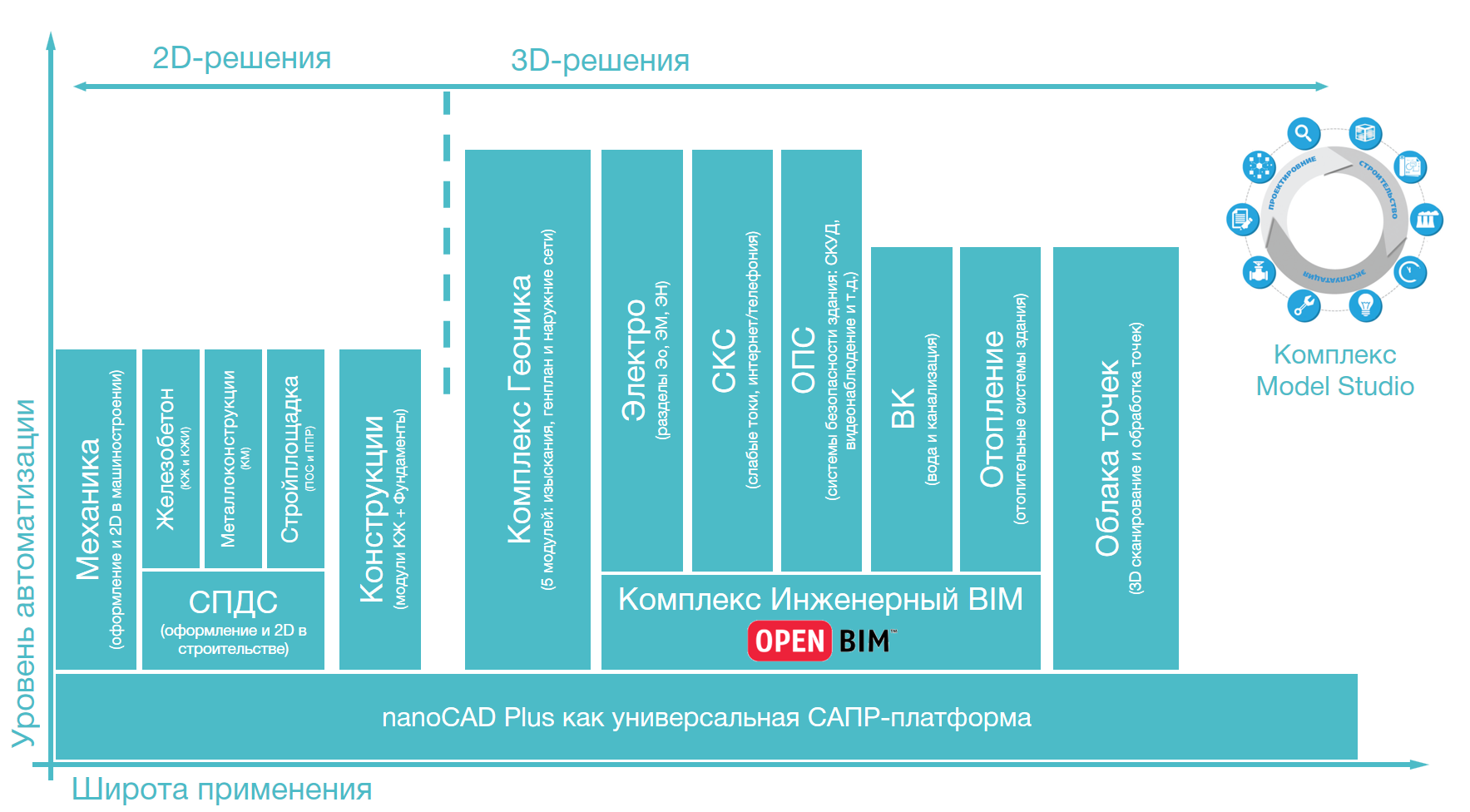
Fig. 3. Scheme of specialized solutions from CSoft Development based on the nanoCAD Plus platform (clickable)
This function of the nanoCAD Plus platform is actively used by our colleagues from CSoft Development , who at one time developed specialized applications for the AutoCAD platform, and now ported part of their solutions to the nanoCAD Plus platform, reducing the cost of the underlying CAD platform for its users (Fig. 3) . The solutions are different - and relatively simple, automating 2D drawing (concentrating on the design according to Russian standards in construction (DPS) or machine-building (Mechanics) design), and quite complex, implementing intelligent three-dimensional modeling with the functions of automatic creation of drawings, tables, reports, etc. .P. The latter include three major areas: Geonika for land management, Engineering BIM for the design of engineering networks of the building, Model Studio CS complex for the design of industrial facilities. Choose solutions that fit your needs, implement and automate your work at a new level ...
In design organizations, such applications are usually integrated with each other on the basis of open or agreed formats, supplemented by design modules and highly specialized developments of other companies, their own developments, and together form a unique CAD system, sharpened by the tasks of a specific project group.Everything is simple - it is in such integration and support of such a complex that the work of the CAD department of any self-respecting design organization lies ... if there is such a division, of course ... :-)
And this is precisely what makes the nanoCAD Plus platform interesting - it gives you a fundamental opportunity to expand and sharpen develop the organization's CAD system, combining its financial, organizational and resource capabilities. Even if something is not in the nanoCAD platform, it can be used as a regular graphical editor for your own application: go to the site developer.nanocad.ru where the Developer Club is organized, and get access to the free license for the nanoCAD Plus platform, developer documentation in Russian and the developer forum, which gives you the opportunity to talk with our developers, discuss the complexity of CAD programming and the DWG format, find effective solutions ...
So is nanoCAD Plus a modern CAD system?
Yes!This is the main advantage of nanoCAD Plus. Until now, there were only a few similar solutions in the world, and all of them developed in other countries — primarily in the USA. We in Russia simply used the solutions provided without the ability to influence their development. Now we have our own CAD-platform, which is being developed taking into account the tasks of our country.
It is the separation of tasks that allows us, the developers of the nanoCAD Plus platform, to concentrate on the development of basic CAD capabilities. I’m talking about modern fundamental functions that are “zabronzoveli” and are needed by both end users and developers of specialized applications. There is support for new versions of the DWG format, work with large amounts of data, and functionality for working with point clouds (three-dimensional scanning), and support for information modeling technology at a basic level (import of IFC / BIM format), and three-dimensional parametric modeling, and much - much more ...
The main idea of this section of my article: providing the opportunity to develop new technologies based on the nanoCAD Plus platform for third-party applications, we can polish and develop the basic functions of a CAD solution (foundation) so that it becomes faster, better, more convenient, more modern as a user’s point of view and from the point of view of developers, CAD managers, managers. All And here I personally do not see the limits of cultivation ...
The functionality of the domestic CAD platform nanoCAD Plus
Now, after the general positioning of the nanoCAD Plus platform, let's go through the functionality that we have achieved for the release of the tenth version.
And here I have difficulties: if I start to paint every function now, it will be long, tedious and hard - now in nanoCAD Plus there are more than 500 CAD commands that are wrapped in more than 1270 English and 975 Russian aliases (abbreviations) and control more than 530 dwg-variables. To some extent, nanoCAD Plus is the operating system in the world of CAD.
Therefore, I usually present the nanoCAD Plus platform in key areas. And they are the following ...
Direct DWG format support (from eng. Drawing - drawing)
Why is this direction key? Because the DWG format is now the most popular CAD format. According to experts, there are now billions of drawings in this format in the world, huge archives of already developed documentation have been created, integration between solutions has been built, there is user knowledge and technical support experience. Now I have little idea of the situation in which we all abandon this format and begin to invent something new ...
Interestingly, this is now a public format - at one time Autodesk tried to consolidate it, but the US Patent and Trademark Office ( USPTO) recognized that the .dwg format is independent of Autodesk (if this is briefly - in general, the story is quite funny and long. For those interested, start by reading Wikipedia, the section "Legal issues ":). The latest efforts of Autodesk lie in the plane of separation of the .dwg format and the DWG technological environment, the originality of the technology - in general, the subtleties of marketing and positioning ...
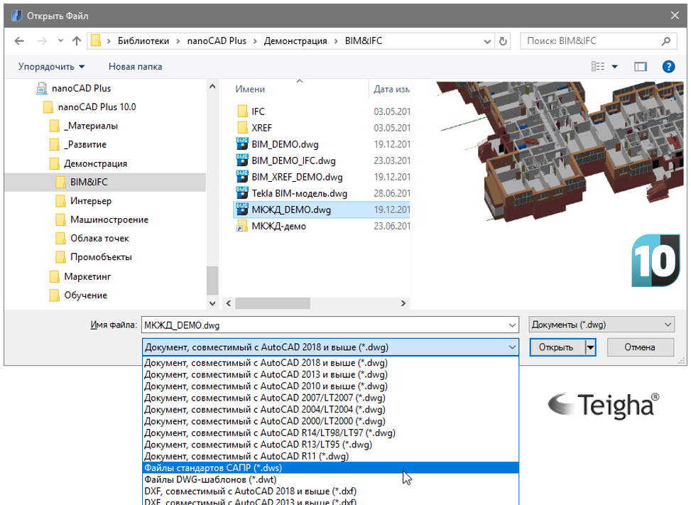
Fig. 4. The .dwg format is the main format of the nanoCAD Plus 10 platform, which supports all its versions - from R11 (DOS times) to the modern DWG2018
Let's return to nanoCAD Plus (Fig. 4): the .dwg format is the native format of the platform, which supports all its versions by the tenth version - from R11 (DOS times) to the modern DWG2018 (updated by Autodesk in May 2017). For users, this means that their work in the form of drawings, catalogs of blocks, archives and integrations with other solutions will be maintained to the maximum extent possible. No conversions and data conversion, transit storage of third-party data (PROXY-objects of specialized solutions) guarantees that by opening DWG files in nanoCAD Plus, you can edit them and return them to the environment where you started editing the documentation.
And in what environments can you return the DWG file so without losing data?
, , DWG, , - ( DWG-). , , , DWG-. DWG DWG – : . , , . , . , , …
You doubt that we correctly open DWG-files and show everything? Hmm, there is, of course, a chance that something will not be opened and displayed correctly, but for us now dead DWG-files are more likely an abnormal situation that we need to deal with as part of technical support. And on the official forum, we even created a special subsection ( link ) to collect such problematic DWG files and promptly improve the work algorithms in such cases. So look, check your files and if you find something problematic, then send us - we will analyze with pleasure.
And, of course, we are sent both broken DWGs and broken ones, which cannot be opened in other DWG environments either. We analyze them free of charge within the framework of technical support, correct and give recommendations. And in parallel we generalize the information and write / develop utilities for their correction. By the way, now in nanoCAD Plus 10, in addition to the classic utilities for servicing the DWG format (PURGE, AUDIT, RECOVER - from the English. "Clear", "Check" and "Restore"), there are three more unique ones:
- Splitting / deleting PROXY objects: that is, deleting non-editable data that remained after running vertical applications.
- Paying for z-coordinates of objects: a utility that allows you to recover geometrically broken drawings (see video 2). Three years ago, I even wrote an article on Habr: link . Very relevant so far.
- DWG-: , , DOS-. - DWG-, ; (. 3).
2. DWG- nanoCAD Plus: z-.
Video 3. An example of working with problematic DWG files in the nanoCAD Plus platform: restoring the file encoding and Cyrillic in the names of layers, blocks, styles, etc.
Another undoubted advantage of nanoCAD and its support of the DWG format is that we completely control what is stored inside the DWG file — there are conspiracy theories that some additional encrypted data can be saved. In nanoCAD Plus, this is definitely not - I tell you as a developer. Only the service information required for the file to work. Ready to pass certification if you do not believe ...
But the format itself is simply a form of storing information on a hard disk or in RAM. The DWG format is valuable precisely by the technologies with which it is wrapped. The technology of working “model sheets” (which is necessary for modeling and producing working drawings at different scales on physical sheets of paper), technology of styles for CAD elements (texts, callouts, tables, etc.), various types of substrates (DWG / XREF , PDF and competing DWF, raster substrates, etc.), utilities for maintaining the quality of DWG (which is essentially a database that requires maintenance), data standardization technologies, and much more. And we support all these DWG technologies as part of the nanoCAD Plus platform.
Therefore, it can be said that the nanoCAD Plus platform provides the best support for the DWG format among all Russian developments, and no one in Russia knows the DWG format better than us. Is it boastful? Perhaps, but I am deeply convinced of this.
Application Programming Interface (API)
Another key aspect of nanoCAD Plus (as I explained above) is the API or a set of ready-made classes, procedures, functions, structures and constants provided by the application for use in external software products. And this API in CAD systems like nanoCAD Plus depends on the DWG format.
nanoCAD Plus supports a DWG-compatible programming interface that allows you to manage the structure, data, methods, and other elements of a drawing using various languages and programming environments. In practice, this means that you can write in .NET, C / C ++, JavaScript, Visual Basic Script, LISP and other scripting languages from various media (for example, from Visual Studio or from Microsoft Excel software) your applications that draw in nanoCAD Plus. Or simulate. Or calculated. Or they take data from an external database and load DWG objects into attributes. Or do something else that you need.
And these applications will be technology compatible with any other DWG-environments that directly support the DWG format and build their work on the database of the DWG format. Full freedom of action, development and compatibility ...
Appearance of the program (or interface)
A very important component for any user is the interface of the program, how it communicates with its user. Important because it is through the interface that users perceive the program and draw conclusions about its convenience. By the tenth version, nanoCAD Plus has two types of interface:
- classic interface (or menu-toolbar). This is one of the oldest graphic methods of program interaction with the user. Windows 3.11, released in 1990, made it as popular as possible, and for almost 30 years, users and developers polished the method to near perfection;
- ( , ). , Windows 2007 , .
There is a set of service functions around the interface that nanoCAD also supports: for example, support for multi-document mode of operation or customization tools (settings) of the user interface. But a separate interesting task, which our developers are constantly engaged in, is the honing of modern interface technologies to the requirements of CAD. For example, implementing the ribbon interface in the tenth version, which has not yet become classical (note how many requests for the topic “how to switch from the ribbon interface to the classical one” on the Internet), which means that users don’t accept the ribbon interface as there are in other CAD systems), we spent a lot of time on its analysis and adjustment to the specific requirements and tasks of CAD users. In particular, we drew convenient readable visual icons,reflecting the specifics of the design, thought through the organization of tabs, groups, sizes of these icons on the ribbon and much more. By the way, now in nanoCAD Plus there are about a thousand icons replicated for different interface classes, standard sizes, color schemes (skins) and monitor resolutions! Imagine the amount of work associated with the update of the icon series? :)
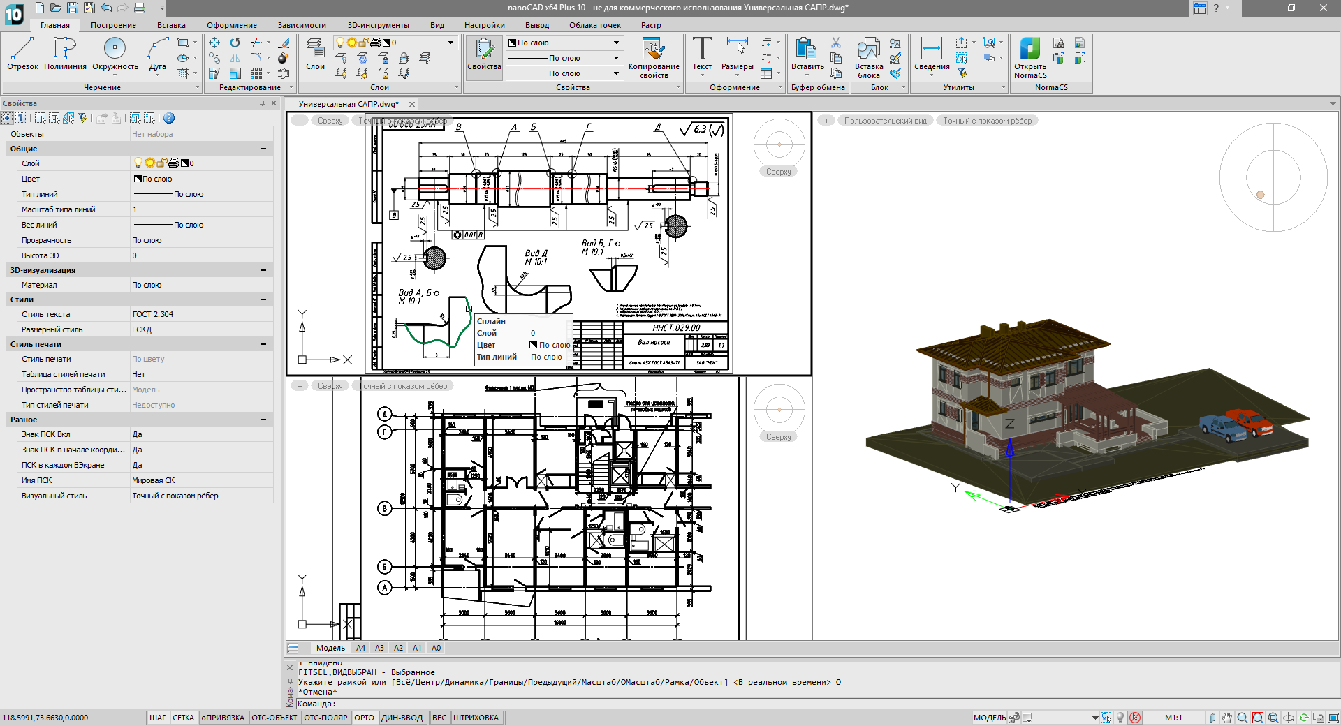
Fig. 5. nanoCAD Plus -, 1-2 ()
In the nanoCAD Plus environment, there are a huge number of interfaces that help working on the drawings and which have already become established principles of work in computer-aided design systems: for example, such specific functions as working with the command line (and dynamic command list), dynamic information input, management of objects and blocks through specialized grips (from the English. Grips - knobs) and additional pop-up context menus (changing depending on the current editing element), means of navigation formation in three-dimensional space and the construction of auxiliary lines / planes for ease of drawing. Therefore, in general, nanoCAD Plus is not surprising for experienced designers - everything in the nanoCAD Plus environment is very familiar and ... classic (Fig. 5).
As developers, we constantly receive requests: why do not you support other operating systems (why only Windows)? Or why not include new interface technologies (for example, circular right-click menus)? Or methods of entering information (for example, voice control)? The answer is: CAD-platform is a conservative thing that primarily solves the problems of users. And we need to find a balance between the new, convenient and familiar to users who have been working in CAD for a long time. New methods of interfaces, input of information - without problems within the framework of new specialized solutions, but only proven and verified solutions are included in the platform. Accordingly, we have no goal to transfer our product to new operating systems - we are ready to move under them only when they become mass. Excuse me,but in this regard, CAD systems are rather inert ...
The main task of nanoCAD Plus as a CAD platform is to ensure that designers get started in the shortest possible time. According to my feelings, with nanoCAD Plus, you can start working within 1-2 days without any problems: set, run, set to work. A couple of hours - and released a drawing.
Such an approach is useful to everyone: both users who have the least stress from changing a solution with a minimum distraction from their main job, CAD specialists who can easily support a new solution in an organization and ensure a transition without major infrastructure changes, and managers for whom the cost is reduced introducing and supporting new CAD systems, and finding new specialists is easy.
Drawing / Editing Tools
Without a doubt, being a full-fledged tool for developing drawings, nanoCAD Plus cannot fail to contain all the necessary tools of classical design (Fig. 6) in the style of an electronic drawing board. In particular, nanoCAD Plus version 10 allows you to:
- create and edit various 2D and 3D vector primitives: segments, 2D and 3D polylines, arcs, circles, ellipses, splines, hatching (regular and gradient), surface objects (box, sphere, pyramid, torus, arbitrary network, etc.) d)
- use different coordinate systems: world polar and cartesian, user, species, etc., switching between them on the fly;
- combine primitives into more intelligent reusable blocks, and then assemble the blocks into catalogs - to automate and accelerate the design;
- ;
- : ( ISO), , SHX- TTF-, , , ..;
- ( ISO), ;
- , (XREF-, , , , ), IFC, DWG, PDF, ( 3D-);
- , , .
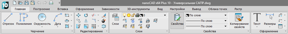
Fig. 6. nanoCAD Plus , –
Wrap all this with different service functions - for example, for spell checking taking into account GOST abbreviations, working with different types of bindings (temporary / permanent, to vectors, PDF and raster substrates), working tables in Excel-like mode; Add Express Tools functions that speed up individual drawing operations, tools for managing the order of drawing, checking and restoring drawing geometry, checking the relevance of references to regulatory documents (normaudit), analyzing the internal structure of a DWG document and many others - and you will understand that nanoCAD Plus is not just a program. This is a whole world for a designer who can be studied for years, increasing his productivity and automating work.
Techniques that extend classic drafting
There are two more technologies that we still keep out of the basic functionality of the nanoCAD Plus: I mean solid-state three-dimensional modeling technology and parametrization technology. They are supplied as optional modules. Let's describe them.
Solid State 3D Modeling Module
This module adds the functionality of universal three-dimensional solid modeling (from Solid Modeling) to the nanoCAD Plus platform: using the tools of extruding faces, rotating closed contours, pulling and building transitions, the user can create complex three-dimensional scenes of almost any geometric shape. And with the help of the section function, you can get automatically updated two-dimensional views, thus linking the model and 2D documentation. Technically, all the mathematics associated with calculating three-dimensional geometry (intersecting or subtracting two figures, building a section, chamfering faces, etc.) is entrusted to an external module, called a geometric core (for more information on the Internet, for example, Dmitry Ushakov’s article “ Geometric kernels in the world and in Russia").
Initially, we conceived so that the external geometric core was wrapped in a special interface-layer and could change from one to another without visual distinction for the user (and programs that communicate with nanoCAD through the API). As a result, in nanoCAD Plus 10, the module of three-dimensional solid modeling is based on geometric cores from two companies (optional):
- ACIS core: development began in 1986 by Spatial (USA), but over time, Dassault Systèmes (France) became the owner of the core. This is one of the most famous cores for 3D-modeling with the best combination of "price-quality", and it was connected to the nanoCAD Plus first;
- C3D: , 1995 , 2012- . , 2018 nanoCAD Plus.
Which kernel is better? This is an ambiguous question. On the one hand, ACIS is more popular, included in many software products, has long been developed. But C3D is a Russian development (import substitution) and is actively developing. In addition, the C3D core provides more functions: in the 10th version of nanoCAD Plus, it additionally provides the import and export functions of popular 3D formats (SAT, STL, IGES, VMRL, etc.), and in the future it is assumed that other long awaited tasty features. This is a competition and we, as developers of the basic CAD platform, do not want to give someone special preferences - the choice is up to the users. But the core of C3D in nanoCAD Plus 10 is set to use by default - we would like to develop Russian technologies.
How does 3D modeling by solid-state technology differ, for example, from information modeling? Indeed, there are so many ways to create a three-dimensional model that an inexperienced user can get confused. The fact is that the data in three-dimensional space can be completely different: you will draw a line in three coordinates, and that’s all - welcome to 3D space. With the development of technology, functional three-dimensional modeling is also evolving. And now we can distinguish the following technologies that are supported by the nanoCAD Plus platform:
- 3D: , , . 2D- – , , , , .. – 3D- ( ), 3D- ().
- 3D-: , , , , , .. , - (, , ), . , .
- : ( ) , : , .. , ( ). .
- Information modeling: here they are working not with surfaces and 3D primitives, but with objects (shaft, gear, bearing, wall, window, door, pump, etc.). In addition to geometry, such objects carry the rules of interaction with other objects, the behavior of an object in three-dimensional space and imitation of interaction appear. Plus filling information about the material, its hardness, method of production, etc.
In the nanoCAD Plus platform, the first two ways of working in 3D-space go in the base delivery, the third - with the help of an additional module, and the fourth - with the help of specialized applications that define such objects, model their behavior and interaction with each other.
Parametric 2D dependency module
The module allows you to impose on the two-dimensional data dependencies of different types: fixed distance, parallelism, perpendicularity, alignment, etc. Any dependence can turn into a parameter and participate in the formulas determining the geometry of the drawing. This leads to the creation of parametric drawings, controlled by the user through key parameters. By activating a 3D module, you can do modern parametric 3D modeling, significantly speeding up your work (video 4).
Video 4. An example of working with a three-dimensional model using the modules "3D modeling" and "2D dependencies".
Overview of unique features
Very often, when I describe in detail the technical functionality of the nanoCAD Plus, impatient users interrupt me and ask the question: “Everything that you have said before is in Western CAD systems. Do you have anything special? ”That is, the very fact that now there is a similar thing in Russian CAD systems does not impress them. Well, then you can concentrate on a review of the unique functions of nanoCAD, which you will not find in other DWG-like systems ...
Support for Russian standards
nanoCAD Plus is developed in Russia and primarily for the markets operating according to Russian design standards. Without any additional settings you can use sheet formats according to GOST 2.301-68, scales according to GOST 2.302-68, line types according to GOST 2.303-68, fonts according to GOST 2.304-81 (both SHX and TTF), hatching according to GOST 2.306-68, dimensions according to GOST 2.307-2011 and callouts according to GOST 2.316-2008 (Fig. 7). Pay attention - all these are fundamental, obligatory to use by GOST 2.3XX, which were laid in the 60s of the last century, and then updated to modern realities. Plus, nanoCAD allows you to take into account the requirements for design and working documentation (GOST R 21.1101-2013) and the rules for the implementation of working documentation of architectural and design solutions (GOST 21.501-2011). In general, a complete set of basic Russian standards,which must take into account when developing drawings all modern designers.
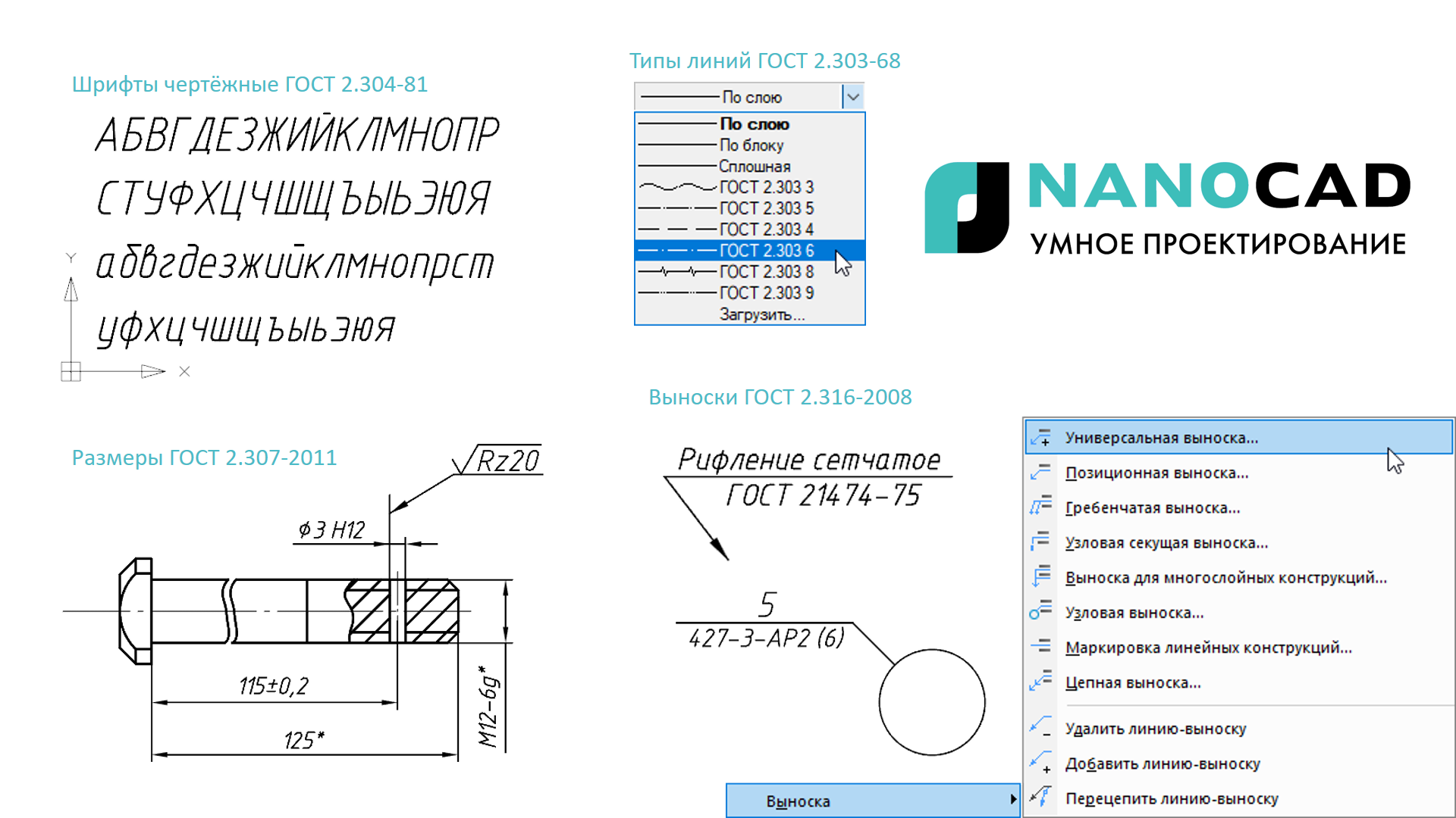
Fig. 7. The nanoCAD Plus platform is pre-configured to work according to Russian design standards (GOST standards 2.3XX series).
I note that within specialized solutions based on nanoCAD Plus, industry-specific Russian standards are often taken into account: engineering calculations for various methods, rules for the design of industry documentation, integration rules, design and much more - see the descriptions of the relevant specialized solutions.
It remains to add that the development of standards will also be reflected in the nanoCAD Plus platform: everything that, in the opinion of our users, should be added to the basic CAD platform, or everything that appears in Russian standards with the development of the regulatory framework, will be added, updated and developed in the nanoCAD Plus platform. For standards support tools have been made for that.
Normaudit drawing and standardization of the organization
Another example of linking the nanoCAD Plus platform with Russian standards is the NORMAAUDIT function. What is its meaning?
Video 5. The unique function of the NORMAAUDIT platform nanoCAD Plus allows you to check the correctness of references from the drawing to the regulatory and technical documentation.
In developing the documentation, the designers regularly refer to the regulatory and technical documentation - in texts, callouts, tables, stamps, blocks, etc .: “assembly should be carried out in accordance with technical specifications XXXX.XXX 2006”, “surface processed according to SanPiN XXX .XX ”,“ apply steel not lower than grade XXX.XXX ”. Often, designers use these phrases on the machine, copying them from one documentation to another. But what if during this time the standard or requirement has been updated? But recently, with the development of technology and regulatory framework, this happens regularly.
The NORMAAUDIT function (video 5) is very similar in its essence to spell checking in text editors: the program analyzes the text, finds pieces that are similar to references to regulatory documents, and makes a list of such analyzed pieces. Further, it is checked against the list of current versions of regulatory documents (taking information from the NormaCS regulatory documents database updated every day) and tints the corresponding pieces on the drawing according to the semaphore principle: the green wavy lines under the text are ok, the red ones are no longer valid. There are other statuses: partially valid (red-green color), the document is on approval (blue), etc. As a result, the designer instantly sees links to inactive documentation and can quickly change the design decision!
In addition to this, starting with the tenth version of nanoCAD Plus, there was a function that standardizes the internal organization of the DWG document: is the designer using the right layers? didn’t the non-standardized types of lines or shading? Do not use incorrect fonts? The nanoCAD Plus platform automatically tracks the internal standard of the organization and signals problems. Accordingly, thousands of designers within the organization equally draw up all the working documentation and produce verified drawings under the control of nanoCAD Plus.
Work with raster underlays: bindings and editing
Very often, when developing new documents, designers use typical solutions: they took an old drawing, scanned it, planted it as a background and visually circled around it — they chopped it into a new document.
The nanoCAD Plus platform offers an alternative way to work with raster substrates, combining three types of tools (see video 6):
- tools for improving the quality of raster substrates: elimination of distortions and nonlinear distortions that the paper introduced during the storage of the document;
- It is an easy way to find out how to use it.
- automated information chipping tools: a user can be tied to characteristic points of a raster drawing (for example, end points, intersections, centers) as to ordinary vector objects.
Video 6. In the nanoCAD Plus platform, raster substrates are full participants in the documentation development process - edit rasters directly from the nanoCAD environment, become attached to primitives and release new versions of documents.
Rasters in nanoCAD Plus and in all applications based on it are full participants in the process of developing documentation, and you instantly and simply put into operation old drawings, documents, typical solutions!
Table editor GOST-tables
The nanoCAD Plus platform has an Excel-like spreadsheet editor unique for DWG-like CAD systems. You can use it both as a tool for generating manual tables, and for building automatically updated tabular reports on data from a DWG drawing (for example, lists of blocks or lengths of polylines). Also, tables can contain formulas, retrieve data from external sources, upload data to popular formats (XLS, TXT, CSV, etc.). A great tool for creating specifications and estimates.
Work with super-large point clouds (3D scanning)
nanoCAD Plus can be used as a viewer of laser scanning results by directly importing 3D point data from LAS, BIN, PTS, PTX, PCD, XYZ formats, which are most popular in this area. At the same time, nanoCAD Plus works comfortably with super-large point clouds (1 billion or more), provides access to the metadata of points (color, angle, scan date, etc.) and generally treats the point cloud as a standard vector object (see video 7). The latter means that you can change insertion points, scale, flip three-dimensional scenes, embed them into three-dimensional models, and also make arbitrary sections on them. Just imagine - with the help of a three-dimensional scanner, you quickly enough bring a reconstructed object into the CAD-environment, and then include it in your work!
Video 7. The nanoCAD Plus platform directly supports popular laser scanning formats and can be used as a super-large point cloud viewer.
IFC format support (OpenBIM)
Another unusual set of data for classic CAD solutions is information models, that is, three-dimensional models of buildings and structures filled with attribute information (weight, manufacturer, design loads, etc., etc.). In principle, no one limits the amount of information that you or your associates can put into the model. At the same time, there is only one official open data format that allows transferring such models between programs, the IFC (Industry Foundation Classes) format. The remaining BIM formats are proprietary. nanoCAD Plus is not designed to create / edit such models and cannot automatically edit such parameters (this is the task of BIM solutions, which can be built on nanoCAD as a platform, but the nanoCAD Plus platform is still a universal CAD editor, not sharpened under the subject area), but to display and analyze is without problems (see video 8).
So, nanoCAD Plus can import an unlimited number of IFC-data into the DWG-environment, thus forming summary BIM-models. At the same time, the user sees the internal structure of the information model, its attributes / parameters, can select any IFC object and get access to the information data in the standard properties window (for example, selecting a column, find out its material, strength, brand, etc.). And an Excel-like spreadsheet editor can be used to automatically assemble the attributes of IFC objects into an updatable table.
Video 8. The nanoCAD Plus platform allows you to combine various data in three-dimensional space: informational BIM models, laser scan results (point clouds), three-dimensional DWG data, etc.
As a result, nanoCAD Plus combines modern BIM technology with a classic DWG environment, creating a bridge between classic design and modern trends.
Navigation in 3D space
The next logical step for the nanoCAD platform, which is aimed at modern design and combines both 2D documentation and various 3D data (3D DWG, BIM models, point clouds) into combined three-dimensional scenes in one environment, to provide users with convenient navigation through models.
We introduced the WASD-principle of navigation in a three-dimensional space into the platform, which is similar to the principles of three-dimensional shooters in the game - see video 9. Now users can analyze three-dimensional documents and models in a fairly intuitive mode.
Dimensions of 3D models
One of the key areas of development of the nanoCAD Plus platform is working with three-dimensional models of large dimensions. Here we combine the modern capabilities of video cards, and multi-threaded computations, and cunning algorithms for processing specific CAD information. All this leads to the fact that the last five years, nanoCAD is accelerating in each version by 10-20% and allows you to now spin much more saturated models than is available in most DWG-like CAD systems. And we will continue this work so that users can comfortably work with large assemblies, large (saturated) building models, vast territories (video 9) ...
Video 9. Convenient navigation tools and the ability to work with loaded models allow users to create more and more complex models and projects.
Flexible licensing and permanent versions
nanoCAD Plus is aimed at different groups of users: from individuals to large design institutes. That is why we are very flexible in our approach to the licensing system and at the moment we offer all types of licenses: temporary and permanent, local and network, with and without modules, for commercial use and for training. Take a look at our price list and find a convenient way for you to use nanoCAD.
Conclusion
So, let's sum up ... In fact, the tenth version of the nanoCAD Plus platform has become a huge functional CAD system, useful to the widest range of users and ready to develop in any new direction. As you can see, even a brief overview of the functions has grown to a multi-page article ...
The basic principles that we laid in our CAD platform and which you will find in the 10th version of the program:
- Classical design aimed at the release of documentation (drawings): reliable, fast, convenient, simple and, most importantly, a universal product.
- Classic and user-friendly interface that provides a simple transition and quick start for users, ease of support and integration into existing business processes for CAD-managers and savings for managers of design organizations due to the large number of ready-made specialists and simple implementation.
- A complete set of functions for designing: from classic two-dimensional tools to modern technologies, tied to subject areas.
- Customization for Russian design standards: scope, design elements, terms - all this is already pre-configured in the base CAD-platform and is expanded in specialized solutions for use in the Russian design market.
- Scalability and specialization: despite the fact that initially nanoCAD is a product with a minimal level of automation, it expands and can automate complex specialized tasks (calculations, automatic drawing, integration, etc.) - see additional applications for the nanoCAD Plus platform from Nanosoft and other developers. And if you are a developer, you have ideas for the development of a new solution and you need a good quality graphical platform with support for the DWG format, then welcome to the world of development for nanoCAD Plus.
- Development: our product develops following the demands of Russian users. You are not satisfied that foreign solutions are delivered in the “as is” mode? Now there is an alternative that takes into account the tasks of such a large country as Russia.
At the same time, we tried to provide users with the widest possible opportunities for working with the product. First of all, the nanoCAD Plus platform is a commercial software product that supports a wide range of licensing: depending on your tasks, you can purchase a permanent or temporary, network or local license, fix the version number or install a product update for service (subscription). In addition, the license for the nanoCAD Plus platform can be expanded with two additional modules for three-dimensional modeling (ACIS or C3D) and the overlay of 2D dependencies. You can configure the platform best for you, or you can discuss the implementation of nanoCAD Plus and user training in your organization by contacting an authorized partner in your region.
You can also independently explore the capabilities of nanoCAD Plus 10 by downloading the fully functional 30-day evaluation version from www.nanocad.ru . Educational institutions are granted training licenses on the www.nanocad.ru website, and an updated open SDK version is offered to application developers (developer documentation is available on developer.nanocad.ru ). We are fully prepared for cooperation and collaboration.
For 10 years, Nanosoft has managed to create a modern, world-class Russian computer-aided design system, with a huge arsenal of opportunities and a multitude of development directions. And it’s not even so much about import substitution - the CAD market and design technologies are constantly evolving, transforming, requiring new methods, knowledge and the work of a scientific school. Now we have on the basis of what to do it all!
Denis Ozhigin,
Technical Director
JSC "Nanosoft"
Source: https://habr.com/ru/post/423253/
All Articles