Reverse engineering rendering "The Witcher 3"
Recently, I began to deal with the rendering of The Witcher 3. This game has amazing rendering techniques. In addition, it is great in terms of plot / music / gameplay.

In this article, I’ll talk about the solutions used to render The Witcher 3. It will not be as comprehensive as the analysis of the graphics of Adrian Corregé’s GTA V , at least for now.
')
We will start with the reverse engineering tonal correction.
In most modern AAA games, one of the stages of rendering is the tonal correction.
Let me remind you that in real life there is a fairly wide range of brightness, while at computer screens it is very limited (8 bits per pixel, which gives us 0-255). It is here that tonemapping comes to the rescue, allowing you to fit a wider one in a limited light interval. Usually there are two data sources in this process: HDR-image with a floating point, the color values of which exceed 1.0, and the average illumination of the scene (the latter can be calculated in several ways, even taking into account the adaptation of the eye to simulate the behavior of human eyes, but here it does not matter)
The next (and last) stage is to obtain an exposure, calculate the color with an exposure and process it using the tone correction curve. And here everything becomes quite confusing, because new concepts appear, such as “white point” (white point) and “middle gray” (middle gray). There are at least a few popular curves, and some of them are discussed in Matt Pettinéo ’s article “A Closer Look at Tone Mapping” .
To be honest, I always had problems with the correct implementation of tone mapping in my own code. There are at least a few different examples on the net that have been helpful to me ... to some extent. Some of them take into account the HDR-brightness / point of white / medium gray, others do not - so they do not really help. I wanted to find a “proven in battles” implementation.
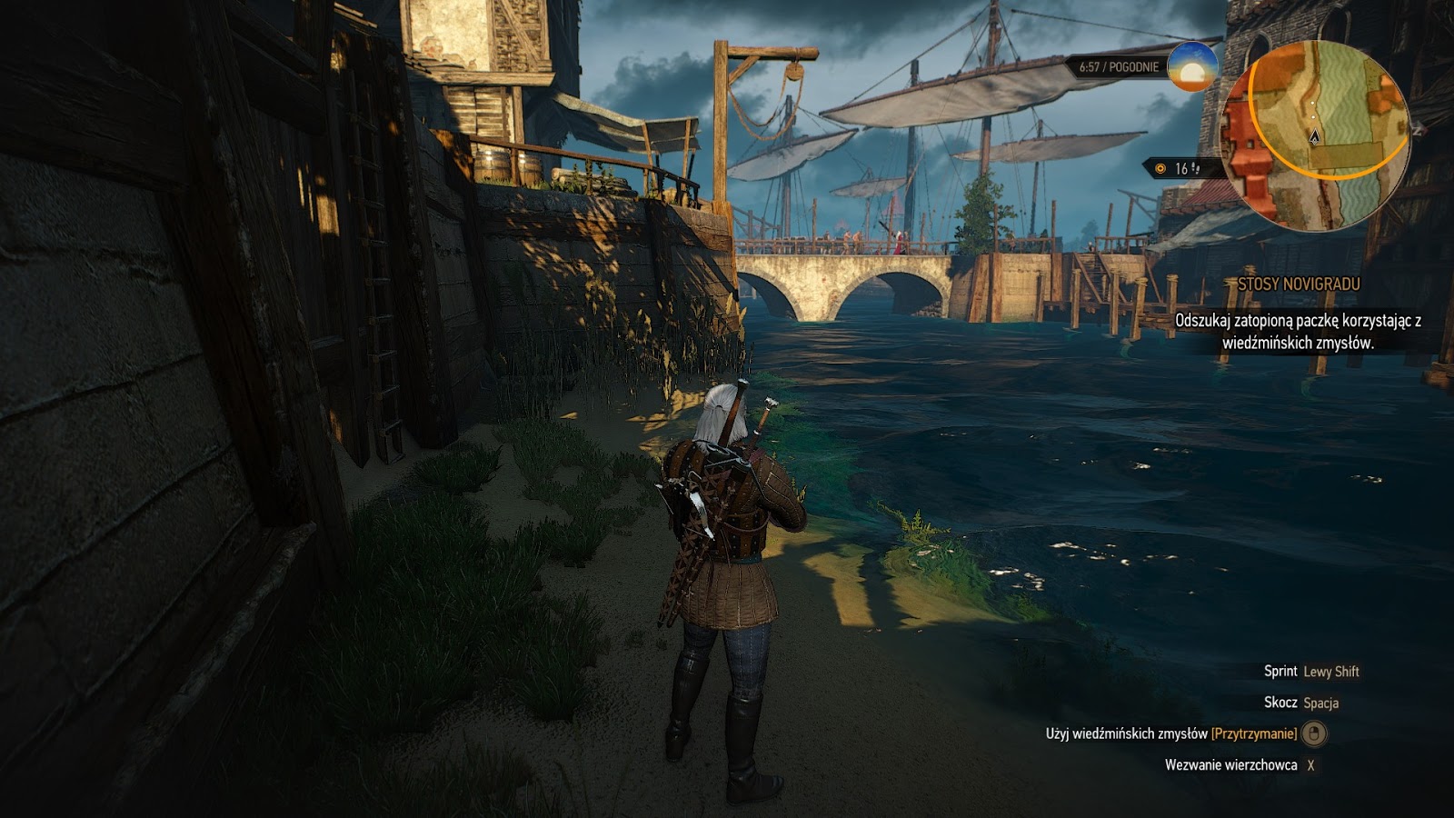
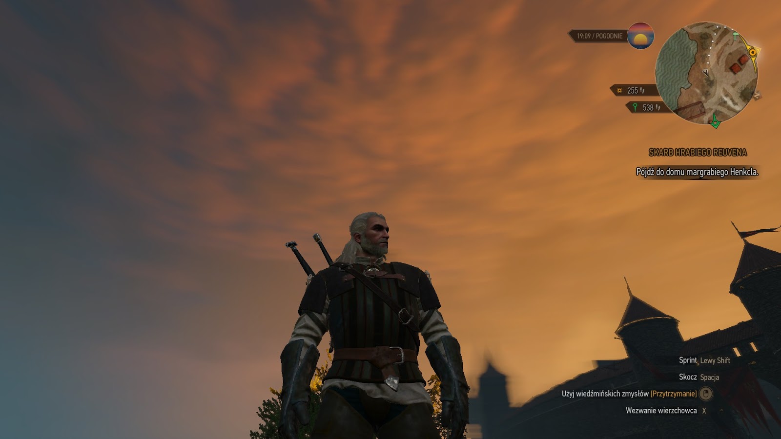
We will work in RenderDoc with the capture of this frame of one of the main quests of Novigrad. All settings are set to maximum:
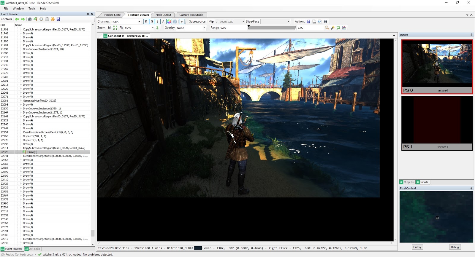
With a bit of searching, I found the draw challenge for tone correction! As I mentioned above, there is a buffer of HDR colors (texture number 0, full resolution) and average scene brightness (texture number 1, 1x1, floating point, computed earlier by the compute shader).
Let's take a look at the pixel shader assembler code:
Here it is worth noting a few points. First, the loaded brightness does not necessarily have to be used, because it is limited (max / min calls) within the values chosen by the artists (from the constant buffer). This is convenient because it allows you to avoid too slow or slow shutter speeds. This move seems rather trivial, but I have never done this before. Secondly, the one who is familiar with the tone correction curves will instantly recognize this value “11.2”, because in fact this is the value of the white point from the Uncharted2 John Heyble tone correction curve.
AF parameters are loaded from cbuffer.
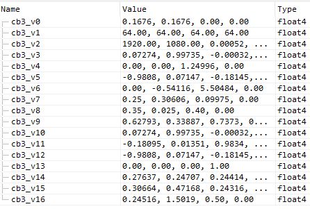
So, we have three more parameters: cb3_v16.x, cb3_v16.y, cb3_v16.z. We can explore their meanings:
My guesses:
I believe that “x” is a kind of “white scale” or medium gray because it is multiplied by 11.2 (line 4), and then used as a numerator in calculating the shutter speed setting (line 10).
“Y” - I called it “the multiplier of the numerator u2”, and soon you will see why.
“Z” is the “exponentiation parameter” because it is used in the log / mul / exp three (in fact, in exponentiation).
But treat these variable names with a bit of skepticism!
Also:
cb3_v4.yz - min / max values of permissible brightness,
cb3_v7.xyz - AC parameters of the curve Uncharted2,
cb3_v8.xyz - parameters of the DF curve Uncharted2.
Now let's get down to the complex - we will write the HLSL shader, which will give us exactly the same assembly code.
This can be very difficult, and the longer the shader, the more difficult the task. Fortunately, some time ago I wrote a tool that allows you to quickly view hlsl-> asm.
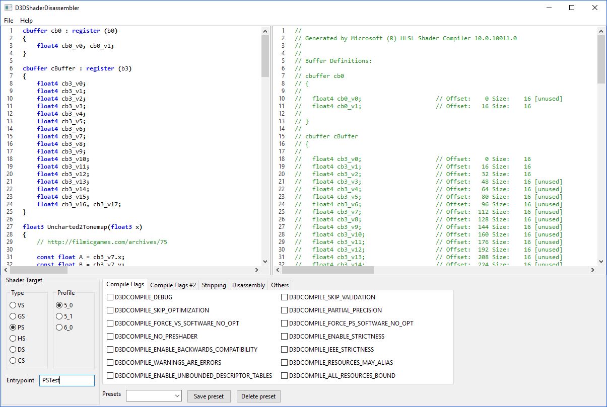
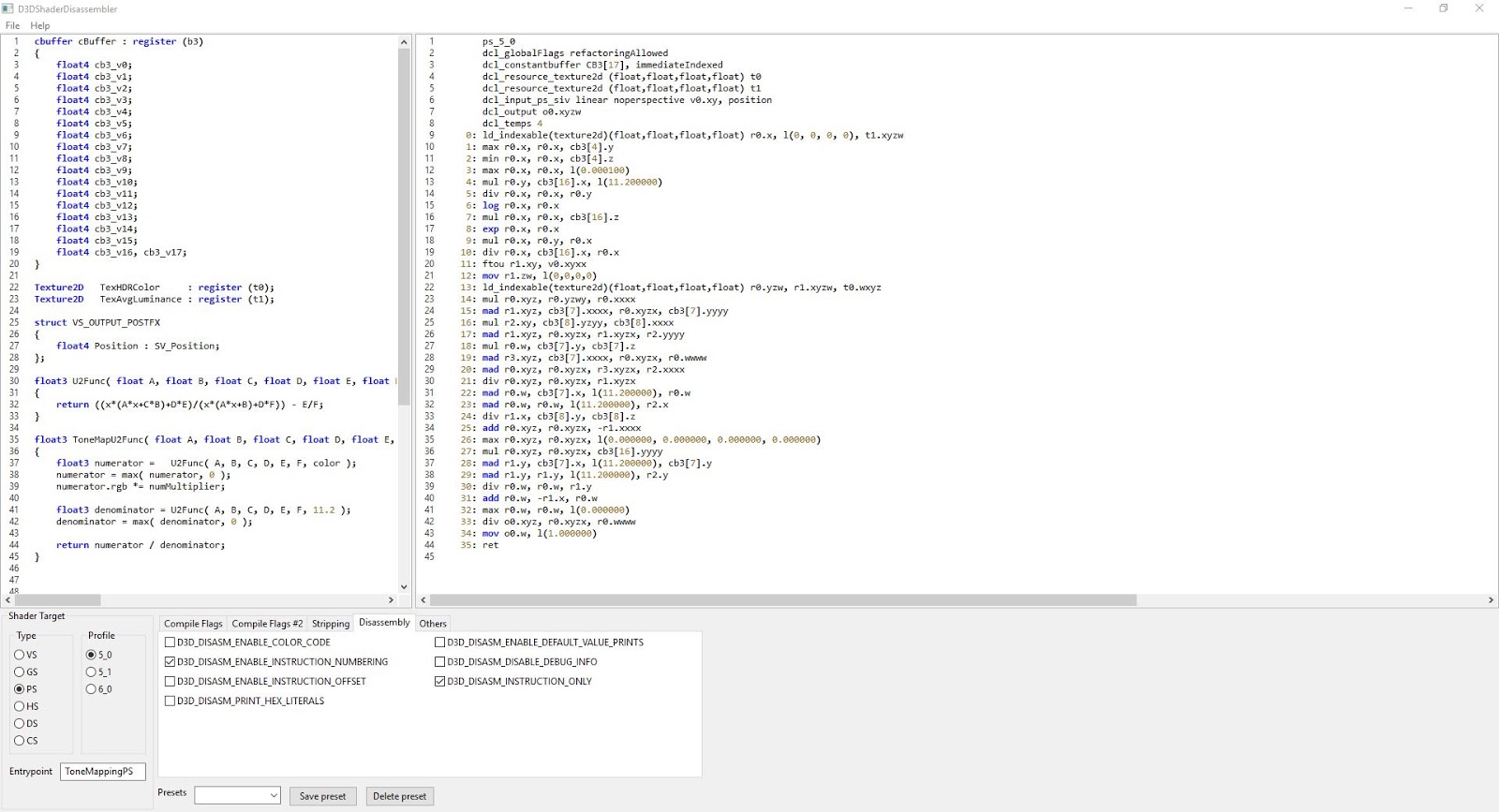
Ladies and gentlemen ... welcome D3DShaderDisassembler!
Having experimented with the code, I received a ready-made HLSL tone correction The Witcher 3 :
A screenshot from my utility to confirm this:
Voila!
I think this is a fairly accurate implementation of the TW3 tone correction, at least in terms of assembly code. I have already applied it in my framework and it works great!
I said “enough” because I have no idea why the denominator in ToneMapU2Func becomes maximum at zero. When dividing by 0, it should be undefined?
This could be finished, but almost by chance I found another version of the TW3 tone correction shader in this frame, used for a beautiful sunset (interestingly, it is used with minimal graphics settings!)
Let's check it out. First, the assembler shader code:
At first, the code may look frightening, but in fact not everything is so bad. After a brief analysis, you can see that there are two calls to the Uncharted2 function with different sets of input data (AF, min / max brightness ...). I have never met such a decision before.
And HLSL:
That is, in fact, we have two sets of control parameters, we calculate two colors with tone correction, and at the end we interpolate them. Smart decision!
The second part will be much easier.
In the first part, I showed how tone correction is performed in TW3. Explaining the theoretical foundations, I briefly mentioned the adaptation of the eye. And you know what? In this part I will talk about how this adaptation of the eye is realized.
But wait, what is eye adaptation and why do we need it? Wikipedia knows everything about it, but I will explain: imagine that you are in a dark room (remember Life is Strange) or in a cave, and go outside, where it is light. For example, the main source of lighting could be the sun.
In the dark, our pupils are dilated, so that more light will fall through them to the retina. When it becomes light, our pupils shrink and sometimes we close our eyes because it is “painful.”
This change does not happen instantly. The eye must adapt to changes in brightness. That is why we adapt the eye when rendering in real time.
A good example of when the lack of eye adaptation is noticeable is the HDRToneMappingCS11 from the DirectX SDK. Abrupt changes in average brightness are rather unpleasant and unnatural.
Let's get started! For the sake of consistency, we will analyze the same frame from Novigrad.
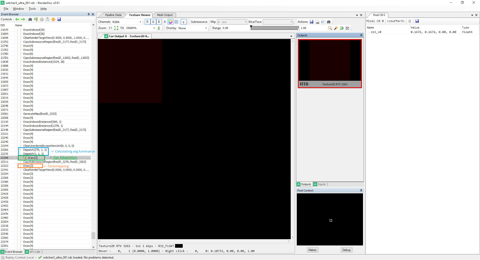
Now we delve into the frame capture program RenderDoc. Eye adaptation is usually performed right before the tone correction, and The Witcher 3 is no exception.
Let's look at the state of the pixel shader:

We have two sources of input data - 2 textures, R32_FLOAT, 1x1 (one pixel). texture0 contains the average brightness of the scene from the previous frame. texture1 contains the average brightness of the scene from the current frame (calculated immediately before this compute shader - I marked it in blue).
It is expected that there is one output - R32_FLOAT, 1x1. Let's look at the pixel shader.
Wow, how simple! Only 7 lines of assembly code. What's going on here? I will explain each line:
0) Get the average brightness of the current frame.
1) Get the average brightness of the previous frame.
2) Perform a check: is the current brightness less than or equal to the brightness of the previous frame?
If yes, then the brightness decreases, if not, the brightness increases.
3) Calculate the difference: difference = currentLum - previousLum.
4) This conditional transfer (movc) assigns a rate factor from the constant buffer. Depending on the result of the test from line 2, two different values can be assigned. This is a smart move, because so you can get different speeds of adaptation and to reduce and increase the brightness. But in the frame under study, both values are the same and vary from 0.11 to 0.3.
5) The final calculation of the adapted brightness: adaptedLuminance = speedFactor * difference + previousLuminance.
6) Shader End
This is implemented in HLSL quite simply:
These lines give us the same assembly code. I would just suggest replacing the type of output data from float4 to float . No need for wasteful bandwidth. This is how the adaptation of the eye is implemented in Witcher 3. Pretty simple, right?
Ps. Many thanks to Baldur Karlsson (Twitter: @baldurk ) for RenderDoc. The program is just great.
Chromatic aberration is an effect mainly found in cheap lenses. It occurs because the lenses have different refractive index for different lengths of visible light. As a result, it appears a visible distortion. However, not everyone likes it. Fortunately, in Witcher 3, this effect is very subtle, and therefore not annoying during the game process (me, at least). But if you want, you can turn it off.
Let's take a closer look at an example of a scene with and without chromatic aberration:

Chromatic aberration enabled
Chromatic aberration disabled
Do you notice any differences near the edges? Me neither. Let's try another scene:
Chromatic aberration is enabled. Notice a slight “red” distortion in the indicated area.
Yeah, much better! Here the contrast between the dark and light areas is stronger, and in the corner we see a slight distortion. As you can see, this effect is very weak. However, I was wondering how it is implemented. Let's move on to the most curious part: the code!
Implementation
The first thing to do is to find the desired render call with a pixel shader. In fact, chromatic aberration is part of the “final post-processing” large pixel shader, which consists of chromatic aberration, vignetting and gamma correction. All this is inside a single pixel shader. Let's take a closer look at the assembler code of the pixel shader:
And to the cbuffer values:

So, let's try to understand what is happening here. Essentially, cb3_v17.xy is the center of chromatic aberration, so the first lines calculate the 2d vector from the coordinates of texels (cb3_v17.zw = the reciprocal of the viewport size) to the “center of chromatic aberration” and its length, then performs other calculations, testing and branching . When applying chromatic aberration, we calculate the displacements using some values from the buffer of the constants and distort the R and G channels. In general, the closer to the edges of the screen, the stronger the effect. Line 10 is quite interesting because it causes the pixels to “move closer”, especially when we exaggerate the aberration. I am pleased to share with you my realization of the effect. As usual, take the names of variables with (solid) skepticism. And note that the effect is applied before gamma correction.
I added “fChromaticAberrationIntensity” to increase the size of the offset, and hence the effect strength, as the name implies (TW3 = 1.0). Intensity = 40:

That's all! Hope you enjoyed this part.
Vignetting is one of the most common post-processing effects used in games. He is popular in photography. Slightly shaded corners can create a beautiful effect. There are several types of vignetting. For example, the Unreal Engine 4 uses natural. But back to The Witcher 3. Click here to see an interactive comparison of frames with and without vignetting. The comparison is taken from The Witcher 3's NVIDIA performance manual .

Screenshot from The Witcher 3 with vignetting turned on.
Note that the upper left corner (the sky) is not as obscured as other parts of the image. We'll come back to this later.
Implementation details
First, there is a slight difference between the vignetting used in the original version of The Witcher 3 (which was released on May 19, 2015) and in The Witcher 3: Blood and Wine. In the first, the “reverse gradient” is calculated inside the pixel shader, and in the last, it is calculated in advance in a 256x256 2D texture:
The texture is 256x256, used as a “reverse gradient” in the “Blood and Wine” supplement.
I will use a shader from Blood and Wine (great game, by the way). As in most other games, the Witcher 3 vignetting is computed in the final post-processing pixel shader. Take a look at the assembler code:
Interesting! It seems that both gamma (line 46) and linear spaces (line 51) are used to calculate vignetting. In line 48, we sample the “reverse gradient” texture. cb3 [9] .xyz is not associated with vignetting. In each scanned frame, it is assigned the value float3 (1.0, 1.0, 1.0), that is, it is probably the final filter used in the effects of fade-in / fade-out gradually dimming / lightening the screen. TW3 has three main parameters for vignetting:

Typical Vignette Mask
But with the help of weights (line 52) you can get very interesting results:

TW3 vignetting mask calculated using weights
Weights are close to 1.0. Look at the data buffer constants of one frame from “Blood and Wine” (of the magical world with a rainbow): that is why vignetting did not affect the bright pixels of the sky mentioned above.

Code
Here is my implementation of TW3 vignetting on HLSL.
GammaToLinear = pow (color, 2.2)
Hope you enjoyed it. You can also try my HLSLexplorer , which greatly helped me in understanding the HLSL assembly code.
As before, take the names of the variables with a bit of skepticism - TW3 shaders are processed by D3DStripShader, so I don’t really know anything about them, I just have to guess. In addition, I do not bear any responsibility for the damage inflicted on your equipment by this shader;)
Bonus: calculating the gradient
In Witcher 3, released in 2015, the inverse gradient was calculated in a pixel shader, and no sampling of a pre-calculated texture was used. Take a look at the assembler code:
Fortunately for us, it is quite simple. On HLSL, it will look something like this:
That is, we simply calculate the distance from the center to the textel, create some magic with it (multiplication, saturate ...), and then ... we calculate the polynomial! Awesome

Let's see how the game "The Witcher 3: Wild Hunt" has the effect of intoxication. If you have not played it yet,then drop everything, buy and play, watch the video:
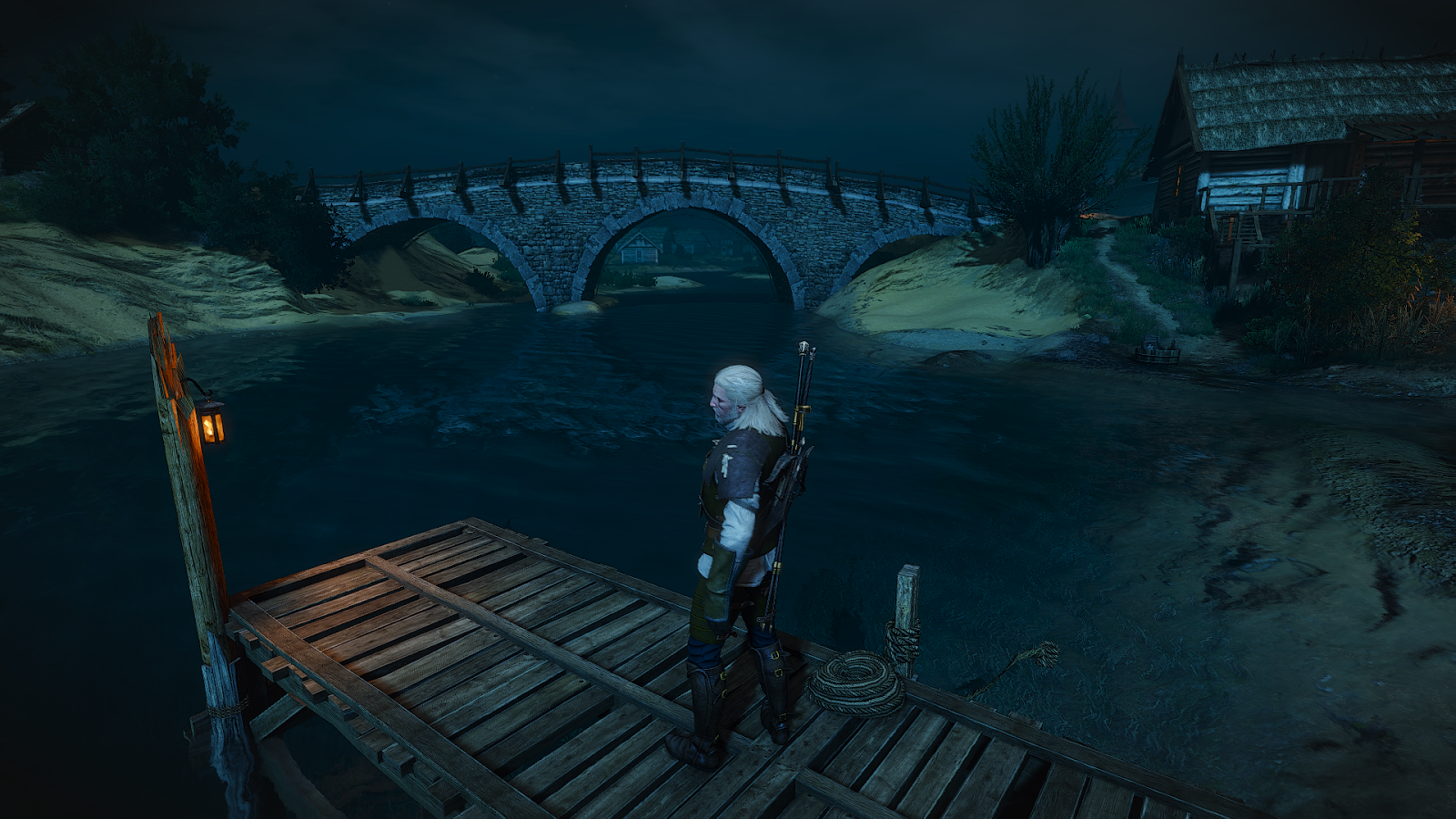
Evening:
Night:
First we see a double and swirling image, often appearing when you drink in real life. The farther a pixel from the center of the image, the stronger the effect of rotation. I deliberately laid out the second video with the night, because you can clearly see this rotation on the stars (see 8 separate points?)
The second part of the effect of intoxication, perhaps not immediately noticeable, is a slight change in zoom. It is noticeable near the center.
It is probably obvious that this effect is a typical post-processing (pixel shader). However, its location in the rendering pipeline may not be so obvious. It turns out that the intoxication effect is applied immediately after the tonal correction and right before the motion blur (the “drunk” image is the input data for the motion blur).
Let's start the games with assembly code:
Two separate constant buffers are used here. Let's check their values:

We are interested in some of them:
cb0_v0.x -> elapsed time (in seconds)
cb0_v1.xyzw - the size of the viewport and the inverse of the size of the viewport (also
known as "pixel size") cb3_v0.x - rotation around the pixel always has a value of 1.0.
cb3_v0.y - the magnitude of the effect of intoxication. After its inclusion does not work in full force, but gradually increases from 0.0 to 1.0.
cv3_v1.xy - pixel offset (more on this below). This is a pair of sin / cos, so if you want, you can use the sincos (time) shader.
cb3_v2.xy is the center of the effect, usually float2 (0.5, 0.5).
Here we want to focus on understanding what is happening, and not just blindly rewrite the shader.
We will start with the first lines:
Line 0 I call the "zoom factor", and soon you will understand why. Immediately after it (line 1), we calculate the “rotation offset”. This is simply the input sin / cos data pair, multiplied by 0.05.
Lines 2-4: First, we calculate the vector from the center of the effect to the UV coordinates of the texture. Then we calculate the square of the distance (3) and the simple distance (4) (from the center to the texel)
Let's consider the following assembly code:
Since they are packaged this way, we can analyze only one pair of floats.
To begin with, r0.yz are “rotation offsets”, r1.z is the distance from center to texel, r1.xy is the vector from center to texel, r0.x is “zoom factor”.
To understand this, let's assume for now that zoomFactor = 1.0, that is, we can write the following:
But zoomFactor = 1.0:
Similarly for r3.xy:
But zoomFactor = 1.0:
Fine.That is, at the moment we essentially have the current TextureUV (texel) ± rotation offset, but what about the zoomFactor? Look at line 0. In essence, zoomFactor = 1.0 - 0.1 * drunkAmount. For maximum drunkAmount, the zoomFactor value should be equal to 0.9, and texture coordinates with zoom are now calculated as follows:
Perhaps the following explanation will be more intuitive: this is just a linear interpolation for some coefficient between the normalized texture coordinates and the center. This is an “zoom close” image. To understand this, it is best to experiment with the values. Here is a link to Shadertoy, where you can see the effect in action.
The entire fragment on the assembly code:
creates a certain gradient, let's call it the “mask of displacement intensity”. In fact, it gives two meanings. The first is in r0.w (we use it later) and the second, 5 times stronger, in r0.x (line 15). The latter actually serves as a texel size multiplier, therefore it affects the bias force.
Rotational Sampling
Next is a series of texture sampling. In fact, 2 series of 8 samples are used, one for each “side”. On HLSL, you can write this as follows:
The trick is that we add to baseTexcoordsA / B the additional offset that lies on the unit circle, multiplied by the previously mentioned "intensity of the shift of texture coordinates." The farther from the center a pixel is, the larger is the radius of the circle around the pixel - we sample it 8 times, which is clearly visible on the stars. Values pointsAroundPixel (multiples of 45 degrees):

Unit Circle
Zoom Sampling
The second part of the intoxication effect in The Witcher 3 is zoom with zooming in and out. Let's take a look at the assembler code that performs this task:
We see that there are three separate texture calls, that is, three different texture coordinates. Let's analyze how texture coordinates are calculated from them. But first, we show the input data for this part:
A few words about the input data. We calculate the displacement in texels (for example, 8.0 * texel size), which is then added to the base uv coordinates. The amplitude simply ranges between 0.98 and 1.02, to give a sense of zoom, like the zoomFactor in the part that performs the rotation.
Let's start with the first pair - r1.xy (line 61)
I.e:
Let's check the second pair - r3.xy (line 62)
I.e:
Let's check the third pair - r0.xy (lines 63-64)
I.e:
All three texture requests are added together, and the result is stored in the r1 register. It is worth noting that this pixel shader uses a sampler with limited addressing.
We connect everything together.
So, at the moment we have the result of rotation in the register r2 and three folded zoom requests in the register r1. Let's look at the last lines of the assembly code:
About additional input data: r0.w is taken from line 7, this is our intensity mask, and cb3 [0] .y is the magnitude of the effect of intoxication.
Let's see how this works. My first approach was brutforce:
But what the hell, no one writes shaders . I took a pencil with paper and wrote this formula:
Where t = effectAmount * intensityMask
So, we get:
And we come to the following:
Yes, this part of the article turned out to be very detailed, but we finally finished! Personally, I learned something in the process of writing, I hope you do too!
If you are interested, the full source code on HLSL is posted here . I checked them with my HLSLexplorer , and although there is no one-on-one correspondence with the original shader, the differences are so small (one less line) that I can say with confidence that it works. Thanks for reading!
In this article, I’ll talk about the solutions used to render The Witcher 3. It will not be as comprehensive as the analysis of the graphics of Adrian Corregé’s GTA V , at least for now.
')
We will start with the reverse engineering tonal correction.
Part 1: Tone Correction
In most modern AAA games, one of the stages of rendering is the tonal correction.
Let me remind you that in real life there is a fairly wide range of brightness, while at computer screens it is very limited (8 bits per pixel, which gives us 0-255). It is here that tonemapping comes to the rescue, allowing you to fit a wider one in a limited light interval. Usually there are two data sources in this process: HDR-image with a floating point, the color values of which exceed 1.0, and the average illumination of the scene (the latter can be calculated in several ways, even taking into account the adaptation of the eye to simulate the behavior of human eyes, but here it does not matter)
The next (and last) stage is to obtain an exposure, calculate the color with an exposure and process it using the tone correction curve. And here everything becomes quite confusing, because new concepts appear, such as “white point” (white point) and “middle gray” (middle gray). There are at least a few popular curves, and some of them are discussed in Matt Pettinéo ’s article “A Closer Look at Tone Mapping” .
To be honest, I always had problems with the correct implementation of tone mapping in my own code. There are at least a few different examples on the net that have been helpful to me ... to some extent. Some of them take into account the HDR-brightness / point of white / medium gray, others do not - so they do not really help. I wanted to find a “proven in battles” implementation.
We will work in RenderDoc with the capture of this frame of one of the main quests of Novigrad. All settings are set to maximum:
With a bit of searching, I found the draw challenge for tone correction! As I mentioned above, there is a buffer of HDR colors (texture number 0, full resolution) and average scene brightness (texture number 1, 1x1, floating point, computed earlier by the compute shader).
Let's take a look at the pixel shader assembler code:
ps_5_0 dcl_globalFlags refactoringAllowed dcl_constantbuffer cb3[17], immediateIndexed dcl_resource_texture2d (float,float,float,float) t0 dcl_resource_texture2d (float,float,float,float) t1 dcl_input_ps_siv v0.xy, position dcl_output o0.xyzw dcl_temps 4 0: ld_indexable(texture2d)(float,float,float,float) r0.x, l(0, 0, 0, 0), t1.xyzw 1: max r0.x, r0.x, cb3[4].y 2: min r0.x, r0.x, cb3[4].z 3: max r0.x, r0.x, l(0.000100) 4: mul r0.y, cb3[16].x, l(11.200000) 5: div r0.x, r0.x, r0.y 6: log r0.x, r0.x 7: mul r0.x, r0.x, cb3[16].z 8: exp r0.x, r0.x 9: mul r0.x, r0.y, r0.x 10: div r0.x, cb3[16].x, r0.x 11: ftou r1.xy, v0.xyxx 12: mov r1.zw, l(0, 0, 0, 0) 13: ld_indexable(texture2d)(float,float,float,float) r0.yzw, r1.xyzw, t0.wxyz 14: mul r0.xyz, r0.yzwy, r0.xxxx 15: mad r1.xyz, cb3[7].xxxx, r0.xyzx, cb3[7].yyyy 16: mul r2.xy, cb3[8].yzyy, cb3[8].xxxx 17: mad r1.xyz, r0.xyzx, r1.xyzx, r2.yyyy 18: mul r0.w, cb3[7].y, cb3[7].z 19: mad r3.xyz, cb3[7].xxxx, r0.xyzx, r0.wwww 20: mad r0.xyz, r0.xyzx, r3.xyzx, r2.xxxx 21: div r0.xyz, r0.xyzx, r1.xyzx 22: mad r0.w, cb3[7].x, l(11.200000), r0.w 23: mad r0.w, r0.w, l(11.200000), r2.x 24: div r1.x, cb3[8].y, cb3[8].z 25: add r0.xyz, r0.xyzx, -r1.xxxx 26: max r0.xyz, r0.xyzx, l(0, 0, 0, 0) 27: mul r0.xyz, r0.xyzx, cb3[16].yyyy 28: mad r1.y, cb3[7].x, l(11.200000), cb3[7].y 29: mad r1.y, r1.y, l(11.200000), r2.y 30: div r0.w, r0.w, r1.y 31: add r0.w, -r1.x, r0.w 32: max r0.w, r0.w, l(0) 33: div o0.xyz, r0.xyzx, r0.wwww 34: mov o0.w, l(1.000000) 35: ret Here it is worth noting a few points. First, the loaded brightness does not necessarily have to be used, because it is limited (max / min calls) within the values chosen by the artists (from the constant buffer). This is convenient because it allows you to avoid too slow or slow shutter speeds. This move seems rather trivial, but I have never done this before. Secondly, the one who is familiar with the tone correction curves will instantly recognize this value “11.2”, because in fact this is the value of the white point from the Uncharted2 John Heyble tone correction curve.
AF parameters are loaded from cbuffer.
So, we have three more parameters: cb3_v16.x, cb3_v16.y, cb3_v16.z. We can explore their meanings:
My guesses:
I believe that “x” is a kind of “white scale” or medium gray because it is multiplied by 11.2 (line 4), and then used as a numerator in calculating the shutter speed setting (line 10).
“Y” - I called it “the multiplier of the numerator u2”, and soon you will see why.
“Z” is the “exponentiation parameter” because it is used in the log / mul / exp three (in fact, in exponentiation).
But treat these variable names with a bit of skepticism!
Also:
cb3_v4.yz - min / max values of permissible brightness,
cb3_v7.xyz - AC parameters of the curve Uncharted2,
cb3_v8.xyz - parameters of the DF curve Uncharted2.
Now let's get down to the complex - we will write the HLSL shader, which will give us exactly the same assembly code.
This can be very difficult, and the longer the shader, the more difficult the task. Fortunately, some time ago I wrote a tool that allows you to quickly view hlsl-> asm.
Ladies and gentlemen ... welcome D3DShaderDisassembler!
Having experimented with the code, I received a ready-made HLSL tone correction The Witcher 3 :
cbuffer cBuffer : register (b3) { float4 cb3_v0; float4 cb3_v1; float4 cb3_v2; float4 cb3_v3; float4 cb3_v4; float4 cb3_v5; float4 cb3_v6; float4 cb3_v7; float4 cb3_v8; float4 cb3_v9; float4 cb3_v10; float4 cb3_v11; float4 cb3_v12; float4 cb3_v13; float4 cb3_v14; float4 cb3_v15; float4 cb3_v16, cb3_v17; } Texture2D TexHDRColor : register (t0); Texture2D TexAvgLuminance : register (t1); struct VS_OUTPUT_POSTFX { float4 Position : SV_Position; }; float3 U2Func( float A, float B, float C, float D, float E, float F, float3 x ) { return ((x*(A*x+C*B)+D*E)/(x*(A*x+B)+D*F)) - E/F; } float3 ToneMapU2Func( float A, float B, float C, float D, float E, float F, float3 color, float numMultiplier ) { float3 numerator = U2Func( A, B, C, D, E, F, color ); numerator = max( numerator, 0 ); numerator.rgb *= numMultiplier; float3 denominator = U2Func( A, B, C, D, E, F, 11.2 ); denominator = max( denominator, 0 ); return numerator / denominator; } float4 ToneMappingPS( VS_OUTPUT_POSTFX Input) : SV_Target0 { float avgLuminance = TexAvgLuminance.Load( int3(0, 0, 0) ); avgLuminance = clamp( avgLuminance, cb3_v4.y, cb3_v4.z ); avgLuminance = max( avgLuminance, 1e-4 ); float scaledWhitePoint = cb3_v16.x * 11.2; float luma = avgLuminance / scaledWhitePoint; luma = pow( luma, cb3_v16.z ); luma = luma * scaledWhitePoint; luma = cb3_v16.x / luma; float3 HDRColor = TexHDRColor.Load( uint3(Input.Position.xy, 0) ).rgb; float3 color = ToneMapU2Func( cb3_v7.x, cb3_v7.y, cb3_v7.z, cb3_v8.x, cb3_v8.y, cb3_v8.z, luma*HDRColor, cb3_v16.y); return float4(color, 1); } A screenshot from my utility to confirm this:
Voila!
I think this is a fairly accurate implementation of the TW3 tone correction, at least in terms of assembly code. I have already applied it in my framework and it works great!
I said “enough” because I have no idea why the denominator in ToneMapU2Func becomes maximum at zero. When dividing by 0, it should be undefined?
This could be finished, but almost by chance I found another version of the TW3 tone correction shader in this frame, used for a beautiful sunset (interestingly, it is used with minimal graphics settings!)
Let's check it out. First, the assembler shader code:
ps_5_0 dcl_globalFlags refactoringAllowed dcl_constantbuffer cb3[18], immediateIndexed dcl_resource_texture2d (float,float,float,float) t0 dcl_resource_texture2d (float,float,float,float) t1 dcl_input_ps_siv v0.xy, position dcl_output o0.xyzw dcl_temps 5 0: ld_indexable(texture2d)(float,float,float,float) r0.x, l(0, 0, 0, 0), t1.xyzw 1: max r0.y, r0.x, cb3[9].y 2: max r0.x, r0.x, cb3[4].y 3: min r0.x, r0.x, cb3[4].z 4: min r0.y, r0.y, cb3[9].z 5: max r0.xy, r0.xyxx, l(0.000100, 0.000100, 0.000000, 0.000000) 6: mul r0.z, cb3[17].x, l(11.200000) 7: div r0.y, r0.y, r0.z 8: log r0.y, r0.y 9: mul r0.y, r0.y, cb3[17].z 10: exp r0.y, r0.y 11: mul r0.y, r0.z, r0.y 12: div r0.y, cb3[17].x, r0.y 13: ftou r1.xy, v0.xyxx 14: mov r1.zw, l(0, 0, 0, 0) 15: ld_indexable(texture2d)(float,float,float,float) r1.xyz, r1.xyzw, t0.xyzw 16: mul r0.yzw, r0.yyyy, r1.xxyz 17: mad r2.xyz, cb3[11].xxxx, r0.yzwy, cb3[11].yyyy 18: mul r3.xy, cb3[12].yzyy, cb3[12].xxxx 19: mad r2.xyz, r0.yzwy, r2.xyzx, r3.yyyy 20: mul r1.w, cb3[11].y, cb3[11].z 21: mad r4.xyz, cb3[11].xxxx, r0.yzwy, r1.wwww 22: mad r0.yzw, r0.yyzw, r4.xxyz, r3.xxxx 23: div r0.yzw, r0.yyzw, r2.xxyz 24: mad r1.w, cb3[11].x, l(11.200000), r1.w 25: mad r1.w, r1.w, l(11.200000), r3.x 26: div r2.x, cb3[12].y, cb3[12].z 27: add r0.yzw, r0.yyzw, -r2.xxxx 28: max r0.yzw, r0.yyzw, l(0, 0, 0, 0) 29: mul r0.yzw, r0.yyzw, cb3[17].yyyy 30: mad r2.y, cb3[11].x, l(11.200000), cb3[11].y 31: mad r2.y, r2.y, l(11.200000), r3.y 32: div r1.w, r1.w, r2.y 33: add r1.w, -r2.x, r1.w 34: max r1.w, r1.w, l(0) 35: div r0.yzw, r0.yyzw, r1.wwww 36: mul r1.w, cb3[16].x, l(11.200000) 37: div r0.x, r0.x, r1.w 38: log r0.x, r0.x 39: mul r0.x, r0.x, cb3[16].z 40: exp r0.x, r0.x 41: mul r0.x, r1.w, r0.x 42: div r0.x, cb3[16].x, r0.x 43: mul r1.xyz, r1.xyzx, r0.xxxx 44: mad r2.xyz, cb3[7].xxxx, r1.xyzx, cb3[7].yyyy 45: mul r3.xy, cb3[8].yzyy, cb3[8].xxxx 46: mad r2.xyz, r1.xyzx, r2.xyzx, r3.yyyy 47: mul r0.x, cb3[7].y, cb3[7].z 48: mad r4.xyz, cb3[7].xxxx, r1.xyzx, r0.xxxx 49: mad r1.xyz, r1.xyzx, r4.xyzx, r3.xxxx 50: div r1.xyz, r1.xyzx, r2.xyzx 51: mad r0.x, cb3[7].x, l(11.200000), r0.x 52: mad r0.x, r0.x, l(11.200000), r3.x 53: div r1.w, cb3[8].y, cb3[8].z 54: add r1.xyz, -r1.wwww, r1.xyzx 55: max r1.xyz, r1.xyzx, l(0, 0, 0, 0) 56: mul r1.xyz, r1.xyzx, cb3[16].yyyy 57: mad r2.x, cb3[7].x, l(11.200000), cb3[7].y 58: mad r2.x, r2.x, l(11.200000), r3.y 59: div r0.x, r0.x, r2.x 60: add r0.x, -r1.w, r0.x 61: max r0.x, r0.x, l(0) 62: div r1.xyz, r1.xyzx, r0.xxxx 63: add r0.xyz, r0.yzwy, -r1.xyzx 64: mad o0.xyz, cb3[13].xxxx, r0.xyzx, r1.xyzx 65: mov o0.w, l(1.000000) 66: ret At first, the code may look frightening, but in fact not everything is so bad. After a brief analysis, you can see that there are two calls to the Uncharted2 function with different sets of input data (AF, min / max brightness ...). I have never met such a decision before.
And HLSL:
cbuffer cBuffer : register (b3) { float4 cb3_v0; float4 cb3_v1; float4 cb3_v2; float4 cb3_v3; float4 cb3_v4; float4 cb3_v5; float4 cb3_v6; float4 cb3_v7; float4 cb3_v8; float4 cb3_v9; float4 cb3_v10; float4 cb3_v11; float4 cb3_v12; float4 cb3_v13; float4 cb3_v14; float4 cb3_v15; float4 cb3_v16, cb3_v17; } Texture2D TexHDRColor : register (t0); Texture2D TexAvgLuminance : register (t1); float3 U2Func( float A, float B, float C, float D, float E, float F, float3 x ) { return ((x*(A*x+C*B)+D*E)/(x*(A*x+B)+D*F)) - E/F; } float3 ToneMapU2Func( float A, float B, float C, float D, float E, float F, float3 color, float numMultiplier ) { float3 numerator = U2Func( A, B, C, D, E, F, color ); numerator = max( numerator, 0 ); numerator.rgb *= numMultiplier; float3 denominator = U2Func( A, B, C, D, E, F, 11.2 ); denominator = max( denominator, 0 ); return numerator / denominator; } struct VS_OUTPUT_POSTFX { float4 Position : SV_Position; }; float getExposure(float avgLuminance, float minLuminance, float maxLuminance, float middleGray, float powParam) { avgLuminance = clamp( avgLuminance, minLuminance, maxLuminance ); avgLuminance = max( avgLuminance, 1e-4 ); float scaledWhitePoint = middleGray * 11.2; float luma = avgLuminance / scaledWhitePoint; luma = pow( luma, powParam); luma = luma * scaledWhitePoint; float exposure = middleGray / luma; return exposure; } float4 ToneMappingPS( VS_OUTPUT_POSTFX Input) : SV_Target0 { float avgLuminance = TexAvgLuminance.Load( int3(0, 0, 0) ); float exposure1 = getExposure( avgLuminance, cb3_v9.y, cb3_v9.z, cb3_v17.x, cb3_v17.z); float exposure2 = getExposure( avgLuminance, cb3_v4.y, cb3_v4.z, cb3_v16.x, cb3_v16.z); float3 HDRColor = TexHDRColor.Load( uint3(Input.Position.xy, 0) ).rgb; float3 color1 = ToneMapU2Func( cb3_v11.x, cb3_v11.y, cb3_v11.z, cb3_v12.x, cb3_v12.y, cb3_v12.z, exposure1*HDRColor, cb3_v17.y); float3 color2 = ToneMapU2Func( cb3_v7.x, cb3_v7.y, cb3_v7.z, cb3_v8.x, cb3_v8.y, cb3_v8.z, exposure2*HDRColor, cb3_v16.y); float3 finalColor = lerp( color2, color1, cb3_v13.x ); return float4(finalColor, 1); } That is, in fact, we have two sets of control parameters, we calculate two colors with tone correction, and at the end we interpolate them. Smart decision!
Part 2: eye adaptation
The second part will be much easier.
In the first part, I showed how tone correction is performed in TW3. Explaining the theoretical foundations, I briefly mentioned the adaptation of the eye. And you know what? In this part I will talk about how this adaptation of the eye is realized.
But wait, what is eye adaptation and why do we need it? Wikipedia knows everything about it, but I will explain: imagine that you are in a dark room (remember Life is Strange) or in a cave, and go outside, where it is light. For example, the main source of lighting could be the sun.
In the dark, our pupils are dilated, so that more light will fall through them to the retina. When it becomes light, our pupils shrink and sometimes we close our eyes because it is “painful.”
This change does not happen instantly. The eye must adapt to changes in brightness. That is why we adapt the eye when rendering in real time.
A good example of when the lack of eye adaptation is noticeable is the HDRToneMappingCS11 from the DirectX SDK. Abrupt changes in average brightness are rather unpleasant and unnatural.
Let's get started! For the sake of consistency, we will analyze the same frame from Novigrad.
Now we delve into the frame capture program RenderDoc. Eye adaptation is usually performed right before the tone correction, and The Witcher 3 is no exception.
Let's look at the state of the pixel shader:
We have two sources of input data - 2 textures, R32_FLOAT, 1x1 (one pixel). texture0 contains the average brightness of the scene from the previous frame. texture1 contains the average brightness of the scene from the current frame (calculated immediately before this compute shader - I marked it in blue).
It is expected that there is one output - R32_FLOAT, 1x1. Let's look at the pixel shader.
ps_5_0 dcl_globalFlags refactoringAllowed dcl_constantbuffer cb3[1], immediateIndexed dcl_sampler s0, mode_default dcl_sampler s1, mode_default dcl_resource_texture2d (float,float,float,float) t0 dcl_resource_texture2d (float,float,float,float) t1 dcl_output o0.xyzw dcl_temps 1 0: sample_l(texture2d)(float,float,float,float) r0.x, l(0, 0, 0, 0), t1.xyzw, s1, l(0) 1: sample_l(texture2d)(float,float,float,float) r0.y, l(0, 0, 0, 0), t0.yxzw, s0, l(0) 2: ge r0.z, r0.y, r0.x 3: add r0.x, -r0.y, r0.x 4: movc r0.z, r0.z, cb3[0].x, cb3[0].y 5: mad o0.xyzw, r0.zzzz, r0.xxxx, r0.yyyy 6: ret Wow, how simple! Only 7 lines of assembly code. What's going on here? I will explain each line:
0) Get the average brightness of the current frame.
1) Get the average brightness of the previous frame.
2) Perform a check: is the current brightness less than or equal to the brightness of the previous frame?
If yes, then the brightness decreases, if not, the brightness increases.
3) Calculate the difference: difference = currentLum - previousLum.
4) This conditional transfer (movc) assigns a rate factor from the constant buffer. Depending on the result of the test from line 2, two different values can be assigned. This is a smart move, because so you can get different speeds of adaptation and to reduce and increase the brightness. But in the frame under study, both values are the same and vary from 0.11 to 0.3.
5) The final calculation of the adapted brightness: adaptedLuminance = speedFactor * difference + previousLuminance.
6) Shader End
This is implemented in HLSL quite simply:
// The Witcher 3 eye adaptation shader cbuffer cBuffer : register (b3) { float4 cb3_v0; } struct VS_OUTPUT_POSTFX { float4 Position : SV_Position; }; SamplerState samplerPointClamp : register (s0); SamplerState samplerPointClamp2 : register (s1); Texture2D TexPreviousAvgLuminance : register (t0); Texture2D TexCurrentAvgLuminance : register (t1); float4 TW3_EyeAdaptationPS(VS_OUTPUT_POSTFX Input) : SV_TARGET { // Get current and previous luminance. float currentAvgLuminance = TexCurrentAvgLuminance.SampleLevel( samplerPointClamp2, float2(0.0, 0.0), 0 ); float previousAvgLuminance = TexPreviousAvgLuminance.SampleLevel( samplerPointClamp, float2(0.0, 0.0), 0 ); // Difference between current and previous luminance. float difference = currentAvgLuminance - previousAvgLuminance; // Scale factor. Can be different for both falling down and rising up of luminance. // It affects speed of adaptation. // Small conditional test is performed here, so different speed can be set differently for both these cases. float adaptationSpeedFactor = (currentAvgLuminance <= previousAvgLuminance) ? cb3_v0.x : cb3_v0.y; // Calculate adapted luminance. float adaptedLuminance = adaptationSpeedFactor * difference + previousAvgLuminance; return adaptedLuminance; } These lines give us the same assembly code. I would just suggest replacing the type of output data from float4 to float . No need for wasteful bandwidth. This is how the adaptation of the eye is implemented in Witcher 3. Pretty simple, right?
Ps. Many thanks to Baldur Karlsson (Twitter: @baldurk ) for RenderDoc. The program is just great.
Part 3: chromatic aberration
Chromatic aberration is an effect mainly found in cheap lenses. It occurs because the lenses have different refractive index for different lengths of visible light. As a result, it appears a visible distortion. However, not everyone likes it. Fortunately, in Witcher 3, this effect is very subtle, and therefore not annoying during the game process (me, at least). But if you want, you can turn it off.
Let's take a closer look at an example of a scene with and without chromatic aberration:
Chromatic aberration enabled
Chromatic aberration disabled
Do you notice any differences near the edges? Me neither. Let's try another scene:
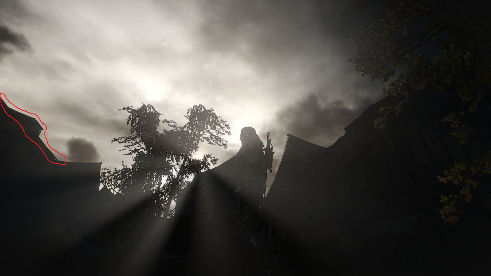
Chromatic aberration is enabled. Notice a slight “red” distortion in the indicated area.
Yeah, much better! Here the contrast between the dark and light areas is stronger, and in the corner we see a slight distortion. As you can see, this effect is very weak. However, I was wondering how it is implemented. Let's move on to the most curious part: the code!
Implementation
The first thing to do is to find the desired render call with a pixel shader. In fact, chromatic aberration is part of the “final post-processing” large pixel shader, which consists of chromatic aberration, vignetting and gamma correction. All this is inside a single pixel shader. Let's take a closer look at the assembler code of the pixel shader:
ps_5_0 dcl_globalFlags refactoringAllowed dcl_constantbuffer cb3[18], immediateIndexed dcl_sampler s1, mode_default dcl_resource_texture2d (float,float,float,float) t0 dcl_input_ps_siv v0.xy, position dcl_input_ps linear v1.zw dcl_output o0.xyzw dcl_temps 4 0: mul r0.xy, v0.xyxx, cb3[17].zwzz 1: mad r0.zw, v0.xxxy, cb3[17].zzzw, -cb3[17].xxxy 2: div r0.zw, r0.zzzw, cb3[17].xxxy 3: dp2 r1.x, r0.zwzz, r0.zwzz 4: sqrt r1.x, r1.x 5: add r1.y, r1.x, -cb3[16].y 6: mul_sat r1.y, r1.y, cb3[16].z 7: sample_l(texture2d)(float,float,float,float) r2.xyz, r0.xyxx, t0.xyzw, s1, l(0) 8: lt r1.z, l(0), r1.y 9: if_nz r1.z 10: mul r1.y, r1.y, r1.y 11: mul r1.y, r1.y, cb3[16].x 12: max r1.x, r1.x, l(0.000100) 13: div r1.x, r1.y, r1.x 14: mul r0.zw, r0.zzzw, r1.xxxx 15: mul r0.zw, r0.zzzw, cb3[17].zzzw 16: mad r0.xy, -r0.zwzz, l(2.000000, 2.000000, 0.000000, 0.000000), r0.xyxx 17: sample_l(texture2d)(float,float,float,float) r2.x, r0.xyxx, t0.xyzw, s1, l(0) 18: mad r0.xy, v0.xyxx, cb3[17].zwzz, -r0.zwzz 19: sample_l(texture2d)(float,float,float,float) r2.y, r0.xyxx, t0.xyzw, s1, l(0) 20: endif ... And to the cbuffer values:
So, let's try to understand what is happening here. Essentially, cb3_v17.xy is the center of chromatic aberration, so the first lines calculate the 2d vector from the coordinates of texels (cb3_v17.zw = the reciprocal of the viewport size) to the “center of chromatic aberration” and its length, then performs other calculations, testing and branching . When applying chromatic aberration, we calculate the displacements using some values from the buffer of the constants and distort the R and G channels. In general, the closer to the edges of the screen, the stronger the effect. Line 10 is quite interesting because it causes the pixels to “move closer”, especially when we exaggerate the aberration. I am pleased to share with you my realization of the effect. As usual, take the names of variables with (solid) skepticism. And note that the effect is applied before gamma correction.
void ChromaticAberration( float2 uv, inout float3 color ) { // User-defined params float2 chromaticAberrationCenter = float2(0.5, 0.5); float chromaticAberrationCenterAvoidanceDistance = 0.2; float fA = 1.25; float fChromaticAbberationIntensity = 30; float fChromaticAberrationDistortionSize = 0.75; // Calculate vector float2 chromaticAberrationOffset = uv - chromaticAberrationCenter; chromaticAberrationOffset = chromaticAberrationOffset / chromaticAberrationCenter; float chromaticAberrationOffsetLength = length(chromaticAberrationOffset); // To avoid applying chromatic aberration in center, subtract small value from // just calculated length. float chromaticAberrationOffsetLengthFixed = chromaticAberrationOffsetLength - chromaticAberrationCenterAvoidanceDistance; float chromaticAberrationTexel = saturate(chromaticAberrationOffsetLengthFixed * fA); float fApplyChromaticAberration = (0.0 < chromaticAberrationTexel); if (fApplyChromaticAberration) { chromaticAberrationTexel *= chromaticAberrationTexel; chromaticAberrationTexel *= fChromaticAberrationDistortionSize; chromaticAberrationOffsetLength = max(chromaticAberrationOffsetLength, 1e-4); float fMultiplier = chromaticAberrationTexel / chromaticAberrationOffsetLength; chromaticAberrationOffset *= fMultiplier; chromaticAberrationOffset *= g_Viewport.zw; chromaticAberrationOffset *= fChromaticAbberationIntensity; float2 offsetUV = -chromaticAberrationOffset * 2 + uv; color.r = TexColorBuffer.SampleLevel(samplerLinearClamp, offsetUV, 0).r; offsetUV = uv - chromaticAberrationOffset; color.g = TexColorBuffer.SampleLevel(samplerLinearClamp, offsetUV, 0).g; } } I added “fChromaticAberrationIntensity” to increase the size of the offset, and hence the effect strength, as the name implies (TW3 = 1.0). Intensity = 40:
That's all! Hope you enjoyed this part.
Part 4: Vignetting
Vignetting is one of the most common post-processing effects used in games. He is popular in photography. Slightly shaded corners can create a beautiful effect. There are several types of vignetting. For example, the Unreal Engine 4 uses natural. But back to The Witcher 3. Click here to see an interactive comparison of frames with and without vignetting. The comparison is taken from The Witcher 3's NVIDIA performance manual .
Screenshot from The Witcher 3 with vignetting turned on.
Note that the upper left corner (the sky) is not as obscured as other parts of the image. We'll come back to this later.
Implementation details
First, there is a slight difference between the vignetting used in the original version of The Witcher 3 (which was released on May 19, 2015) and in The Witcher 3: Blood and Wine. In the first, the “reverse gradient” is calculated inside the pixel shader, and in the last, it is calculated in advance in a 256x256 2D texture:
The texture is 256x256, used as a “reverse gradient” in the “Blood and Wine” supplement.
I will use a shader from Blood and Wine (great game, by the way). As in most other games, the Witcher 3 vignetting is computed in the final post-processing pixel shader. Take a look at the assembler code:
... 44: log r0.xyz, r0.xyzx 45: mul r0.xyz, r0.xyzx, l(0.454545, 0.454545, 0.454545, 0.000000) 46: exp r0.xyz, r0.xyzx 47: mul r1.xyz, r0.xyzx, cb3[9].xyzx 48: sample_indexable(texture2d)(float,float,float,float) r0.w, v1.zwzz, t2.yzwx, s2 49: log r2.xyz, r1.xyzx 50: mul r2.xyz, r2.xyzx, l(2.200000, 2.200000, 2.200000, 0.000000) 51: exp r2.xyz, r2.xyzx 52: dp3 r1.w, r2.xyzx, cb3[6].xyzx 53: add_sat r1.w, -r1.w, l(1.000000) 54: mul r1.w, r1.w, cb3[6].w 55: mul_sat r0.w, r0.w, r1.w 56: mad r0.xyz, -r0.xyzx, cb3[9].xyzx, cb3[7].xyzx 57: mad r0.xyz, r0.wwww, r0.xyzx, r1.xyzx ... Interesting! It seems that both gamma (line 46) and linear spaces (line 51) are used to calculate vignetting. In line 48, we sample the “reverse gradient” texture. cb3 [9] .xyz is not associated with vignetting. In each scanned frame, it is assigned the value float3 (1.0, 1.0, 1.0), that is, it is probably the final filter used in the effects of fade-in / fade-out gradually dimming / lightening the screen. TW3 has three main parameters for vignetting:
- Opacity (cb3 [6] .w) - affects the power of vignetting. 0 - no vignetting, 1 - maximum vignetting. According to my observations, in the base The Witcher 3 it is approximately equal to 1.0, and in “Blood and Wine” it fluctuates around 0.15.
- Color (cb3 [7] .xyz) - an excellent feature of TW3 vignetting is the ability to change its color. It does not have to be black, but in practice ... It usually has the values float3 (3.0 / 255.0, 4.0 / 255.0, 5.0 / 255.0) and so on - in general, these are multiples of 0.00392156 = 1.0 / 255.0
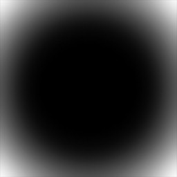
- Weights (cb3 [6] .xyz) is a very interesting parameter. I have always seen “flat” vignettes, such as:
Typical Vignette Mask
But with the help of weights (line 52) you can get very interesting results:
TW3 vignetting mask calculated using weights
Weights are close to 1.0. Look at the data buffer constants of one frame from “Blood and Wine” (of the magical world with a rainbow): that is why vignetting did not affect the bright pixels of the sky mentioned above.
Code
Here is my implementation of TW3 vignetting on HLSL.
GammaToLinear = pow (color, 2.2)
/* // The Witcher 3 vignette. // // Input color is in gamma space // Output color is in gamma space as well. */ float3 Vignette_TW3( in float3 gammaColor, in float3 vignetteColor, in float3 vignetteWeights, in float vignetteOpacity, in Texture2D texVignette, in float2 texUV ) { // For coloring vignette float3 vignetteColorGammaSpace = -gammaColor + vignetteColor; // Calculate vignette amount based on color in *LINEAR* color space and vignette weights. float vignetteWeight = dot( GammaToLinear( gammaColor ), vignetteWeights ); // We need to keep vignette weight in [0-1] range vignetteWeight = saturate( 1.0 - vignetteWeight ); // Multiply by opacity vignetteWeight *= vignetteOpacity; // Obtain vignette mask (here is texture; you can also calculate your custom mask here) float sampledVignetteMask = texVignette.Sample( samplerLinearClamp, texUV ).x; // Final (inversed) vignette mask float finalInvVignetteMask = saturate( vignetteWeight * sampledVignetteMask ); // final composite in gamma space float3 Color = vignetteColorGammaSpace * finalInvVignetteMask + gammaColor.rgb; // * uncomment to debug vignette mask: // return 1.0 - finalInvVignetteMask; // Return final color return Color; } Hope you enjoyed it. You can also try my HLSLexplorer , which greatly helped me in understanding the HLSL assembly code.
As before, take the names of the variables with a bit of skepticism - TW3 shaders are processed by D3DStripShader, so I don’t really know anything about them, I just have to guess. In addition, I do not bear any responsibility for the damage inflicted on your equipment by this shader;)
Bonus: calculating the gradient
In Witcher 3, released in 2015, the inverse gradient was calculated in a pixel shader, and no sampling of a pre-calculated texture was used. Take a look at the assembler code:
35: add r2.xy, v1.zwzz, l(-0.500000, -0.500000, 0.000000, 0.000000) 36: dp2 r1.w, r2.xyxx, r2.xyxx 37: sqrt r1.w, r1.w 38: mad r1.w, r1.w, l(2.000000), l(-0.550000) 39: mul_sat r2.w, r1.w, l(1.219512) 40: mul r2.z, r2.w, r2.w 41: mul r2.xy, r2.zwzz, r2.zzzz 42: dp4 r1.w, l(-0.100000, -0.105000, 1.120000, 0.090000), r2.xyzw 43: min r1.w, r1.w, l(0.940000) Fortunately for us, it is quite simple. On HLSL, it will look something like this:
float TheWitcher3_2015_Mask( in float2 uv ) { float distanceFromCenter = length( uv - float2(0.5, 0.5) ); float x = distanceFromCenter * 2.0 - 0.55; x = saturate( x * 1.219512 ); // 1.219512 = 100/82 float x2 = x * x; float x3 = x2 * x; float x4 = x2 * x2; float outX = dot( float4(x4, x3, x2, x), float4(-0.10, -0.105, 1.12, 0.09) ); outX = min( outX, 0.94 ); return outX; } That is, we simply calculate the distance from the center to the textel, create some magic with it (multiplication, saturate ...), and then ... we calculate the polynomial! Awesome
Part 5: the effect of intoxication
Let's see how the game "The Witcher 3: Wild Hunt" has the effect of intoxication. If you have not played it yet,
Evening:
Night:
First we see a double and swirling image, often appearing when you drink in real life. The farther a pixel from the center of the image, the stronger the effect of rotation. I deliberately laid out the second video with the night, because you can clearly see this rotation on the stars (see 8 separate points?)
The second part of the effect of intoxication, perhaps not immediately noticeable, is a slight change in zoom. It is noticeable near the center.
It is probably obvious that this effect is a typical post-processing (pixel shader). However, its location in the rendering pipeline may not be so obvious. It turns out that the intoxication effect is applied immediately after the tonal correction and right before the motion blur (the “drunk” image is the input data for the motion blur).
Let's start the games with assembly code:
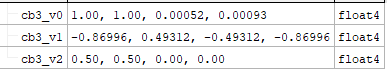
ps_5_0 dcl_globalFlags refactoringAllowed dcl_constantbuffer cb0[2], immediateIndexed dcl_constantbuffer cb3[3], immediateIndexed dcl_sampler s0, mode_default dcl_resource_texture2d (float,float,float,float) t0 dcl_input_ps_siv v1.xy, position dcl_output o0.xyzw dcl_temps 8 0: mad r0.x, cb3[0].y, l(-0.100000), l(1.000000) 1: mul r0.yz, cb3[1].xxyx, l(0.000000, 0.050000, 0.050000, 0.000000) 2: mad r1.xy, v1.xyxx, cb0[1].zwzz, -cb3[2].xyxx 3: dp2 r0.w, r1.xyxx, r1.xyxx 4: sqrt r1.z, r0.w 5: mul r0.w, r0.w, l(10.000000) 6: min r0.w, r0.w, l(1.000000) 7: mul r0.w, r0.w, cb3[0].y 8: mul r2.xyzw, r0.yzyz, r1.zzzz 9: mad r2.xyzw, r1.xyxy, r0.xxxx, -r2.xyzw 10: mul r3.xy, r0.xxxx, r1.xyxx 11: mad r3.xyzw, r0.yzyz, r1.zzzz, r3.xyxy 12: add r3.xyzw, r3.xyzw, cb3[2].xyxy 13: add r2.xyzw, r2.xyzw, cb3[2].xyxy 14: mul r0.x, r0.w, cb3[0].x 15: mul r0.x, r0.x, l(5.000000) 16: mul r4.xyzw, r0.xxxx, cb3[0].zwzw 17: mad r5.xyzw, r4.zwzw, l(1.000000, 0.000000, -1.000000, -0.000000), r2.xyzw 18: sample_indexable(texture2d)(float,float,float,float) r6.xyzw, r5.xyxx, t0.xyzw, s0 19: sample_indexable(texture2d)(float,float,float,float) r5.xyzw, r5.zwzz, t0.xyzw, s0 20: add r5.xyzw, r5.xyzw, r6.xyzw 21: mad r6.xyzw, r4.zwzw, l(0.707000, 0.707000, -0.707000, -0.707000), r2.xyzw 22: sample_indexable(texture2d)(float,float,float,float) r7.xyzw, r6.xyxx, t0.xyzw, s0 23: sample_indexable(texture2d)(float,float,float,float) r6.xyzw, r6.zwzz, t0.xyzw, s0 24: add r5.xyzw, r5.xyzw, r7.xyzw 25: add r5.xyzw, r6.xyzw, r5.xyzw 26: mad r6.xyzw, r4.zwzw, l(0.000000, 1.000000, -0.000000, -1.000000), r2.xyzw 27: mad r2.xyzw, r4.xyzw, l(-0.707000, 0.707000, 0.707000, -0.707000), r2.xyzw 28: sample_indexable(texture2d)(float,float,float,float) r7.xyzw, r6.xyxx, t0.xyzw, s0 29: sample_indexable(texture2d)(float,float,float,float) r6.xyzw, r6.zwzz, t0.xyzw, s0 30: add r5.xyzw, r5.xyzw, r7.xyzw 31: add r5.xyzw, r6.xyzw, r5.xyzw 32: sample_indexable(texture2d)(float,float,float,float) r6.xyzw, r2.xyxx, t0.xyzw, s0 33: sample_indexable(texture2d)(float,float,float,float) r2.xyzw, r2.zwzz, t0.xyzw, s0 34: add r5.xyzw, r5.xyzw, r6.xyzw 35: add r2.xyzw, r2.xyzw, r5.xyzw 36: mul r2.xyzw, r2.xyzw, l(0.062500, 0.062500, 0.062500, 0.062500) 37: mad r5.xyzw, r4.zwzw, l(1.000000, 0.000000, -1.000000, -0.000000), r3.zwzw 38: sample_indexable(texture2d)(float,float,float,float) r6.xyzw, r5.xyxx, t0.xyzw, s0 39: sample_indexable(texture2d)(float,float,float,float) r5.xyzw, r5.zwzz, t0.xyzw, s0 40: add r5.xyzw, r5.xyzw, r6.xyzw 41: mad r6.xyzw, r4.zwzw, l(0.707000, 0.707000, -0.707000, -0.707000), r3.zwzw 42: sample_indexable(texture2d)(float,float,float,float) r7.xyzw, r6.xyxx, t0.xyzw, s0 43: sample_indexable(texture2d)(float,float,float,float) r6.xyzw, r6.zwzz, t0.xyzw, s0 44: add r5.xyzw, r5.xyzw, r7.xyzw 45: add r5.xyzw, r6.xyzw, r5.xyzw 46: mad r6.xyzw, r4.zwzw, l(0.000000, 1.000000, -0.000000, -1.000000), r3.zwzw 47: mad r3.xyzw, r4.xyzw, l(-0.707000, 0.707000, 0.707000, -0.707000), r3.xyzw 48: sample_indexable(texture2d)(float,float,float,float) r4.xyzw, r6.xyxx, t0.xyzw, s0 49: sample_indexable(texture2d)(float,float,float,float) r6.xyzw, r6.zwzz, t0.xyzw, s0 50: add r4.xyzw, r4.xyzw, r5.xyzw 51: add r4.xyzw, r6.xyzw, r4.xyzw 52: sample_indexable(texture2d)(float,float,float,float) r5.xyzw, r3.xyxx, t0.xyzw, s0 53: sample_indexable(texture2d)(float,float,float,float) r3.xyzw, r3.zwzz, t0.xyzw, s0 54: add r4.xyzw, r4.xyzw, r5.xyzw 55: add r3.xyzw, r3.xyzw, r4.xyzw 56: mad r2.xyzw, r3.xyzw, l(0.062500, 0.062500, 0.062500, 0.062500), r2.xyzw 57: mul r0.x, cb3[0].y, l(8.000000) 58: mul r0.xy, r0.xxxx, cb3[0].zwzz 59: mad r0.z, cb3[1].y, l(0.020000), l(1.000000) 60: mul r1.zw, r0.zzzz, r1.xxxy 61: mad r1.xy, r1.xyxx, r0.zzzz, cb3[2].xyxx 62: mad r3.xy, r1.zwzz, r0.xyxx, r1.xyxx 63: mul r0.xy, r0.xyxx, r1.zwzz 64: mad r0.xy, r0.xyxx, l(2.000000, 2.000000, 0.000000, 0.000000), r1.xyxx 65: sample_indexable(texture2d)(float,float,float,float) r1.xyzw, r1.xyxx, t0.xyzw, s0 66: sample_indexable(texture2d)(float,float,float,float) r4.xyzw, r0.xyxx, t0.xyzw, s0 67: sample_indexable(texture2d)(float,float,float,float) r3.xyzw, r3.xyxx, t0.xyzw, s0 68: add r1.xyzw, r1.xyzw, r3.xyzw 69: add r1.xyzw, r4.xyzw, r1.xyzw 70: mad r2.xyzw, -r1.xyzw, l(0.333333, 0.333333, 0.333333, 0.333333), r2.xyzw 71: mul r1.xyzw, r1.xyzw, l(0.333333, 0.333333, 0.333333, 0.333333) 72: mul r0.xyzw, r0.wwww, r2.xyzw 73: mad o0.xyzw, cb3[0].yyyy, r0.xyzw, r1.xyzw 74: ret Two separate constant buffers are used here. Let's check their values:
We are interested in some of them:
cb0_v0.x -> elapsed time (in seconds)
cb0_v1.xyzw - the size of the viewport and the inverse of the size of the viewport (also
known as "pixel size") cb3_v0.x - rotation around the pixel always has a value of 1.0.
cb3_v0.y - the magnitude of the effect of intoxication. After its inclusion does not work in full force, but gradually increases from 0.0 to 1.0.
cv3_v1.xy - pixel offset (more on this below). This is a pair of sin / cos, so if you want, you can use the sincos (time) shader.
cb3_v2.xy is the center of the effect, usually float2 (0.5, 0.5).
Here we want to focus on understanding what is happening, and not just blindly rewrite the shader.
We will start with the first lines:
ps_5_0 0: mad r0.x, cb3[0].y, l(-0.100000), l(1.000000) 1: mul r0.yz, cb3[1].xxyx, l(0.000000, 0.050000, 0.050000, 0.000000) 2: mad r1.xy, v1.xyxx, cb0[1].zwzz, -cb3[2].xyxx 3: dp2 r0.w, r1.xyxx, r1.xyxx 4: sqrt r1.z, r0.w Line 0 I call the "zoom factor", and soon you will understand why. Immediately after it (line 1), we calculate the “rotation offset”. This is simply the input sin / cos data pair, multiplied by 0.05.
Lines 2-4: First, we calculate the vector from the center of the effect to the UV coordinates of the texture. Then we calculate the square of the distance (3) and the simple distance (4) (from the center to the texel)
Texture coordinates with zoom
Let's consider the following assembly code:
8: mul r2.xyzw, r0.yzyz, r1.zzzz 9: mad r2.xyzw, r1.xyxy, r0.xxxx, -r2.xyzw 10: mul r3.xy, r0.xxxx, r1.xyxx 11: mad r3.xyzw, r0.yzyz, r1.zzzz, r3.xyxy 12: add r3.xyzw, r3.xyzw, cb3[2].xyxy 13: add r2.xyzw, r2.xyzw, cb3[2].xyxy Since they are packaged this way, we can analyze only one pair of floats.
To begin with, r0.yz are “rotation offsets”, r1.z is the distance from center to texel, r1.xy is the vector from center to texel, r0.x is “zoom factor”.
To understand this, let's assume for now that zoomFactor = 1.0, that is, we can write the following:
8: mul r2.xyzw, r0.yzyz, r1.zzzz 9: mad r2.xyzw, r1.xyxy, r0.xxxx, -r2.xyzw 13: add r2.xyzw, r2.xyzw, cb3[2].xyxy r2.xy = (texel - center) * zoomFactor - rotationOffsets * distanceFromCenter + center; But zoomFactor = 1.0:
r2.xy = texel - center - rotationOffsets * distanceFromCenter + center; r2.xy = texel - rotationOffsets * distanceFromCenter; Similarly for r3.xy:
10: mul r3.xy, r0.xxxx, r1.xyxx 11: mad r3.xyzw, r0.yzyz, r1.zzzz, r3.xyxy 12: add r3.xyzw, r3.xyzw, cb3[2].xyxy r3.xy = rotationOffsets * distanceFromCenter + zoomFactor * (texel - center) + center But zoomFactor = 1.0:
r3.xy = rotationOffsets * distanceFromCenter + texel - center + center r3.xy = texel + rotationOffsets * distanceFromCenterFine.That is, at the moment we essentially have the current TextureUV (texel) ± rotation offset, but what about the zoomFactor? Look at line 0. In essence, zoomFactor = 1.0 - 0.1 * drunkAmount. For maximum drunkAmount, the zoomFactor value should be equal to 0.9, and texture coordinates with zoom are now calculated as follows:
baseTexcoordsA = 0.9 * texel + 0.1 * center + rotationOffsets * distanceFromCenter baseTexcoordsB = 0.9 * texel + 0.1 * center - rotationOffsets * distanceFromCenter Perhaps the following explanation will be more intuitive: this is just a linear interpolation for some coefficient between the normalized texture coordinates and the center. This is an “zoom close” image. To understand this, it is best to experiment with the values. Here is a link to Shadertoy, where you can see the effect in action.
Offset texture coordinates
The entire fragment on the assembly code:
2: mad r1.xy, v1.xyxx, cb0[1].zwzz, -cb3[2].xyxx 3: dp2 r0.w, r1.xyxx, r1.xyxx 5: mul r0.w, r0.w, l(10.000000) 6: min r0.w, r0.w, l(1.000000) 7: mul r0.w, r0.w, cb3[0].y 14: mul r0.x, r0.w, cb3[0].x 15: mul r0.x, r0.x, l(5.000000) // texcoords offset intensity 16: mul r4.xyzw, r0.xxxx, cb3[0].zwzw // texcoords offset creates a certain gradient, let's call it the “mask of displacement intensity”. In fact, it gives two meanings. The first is in r0.w (we use it later) and the second, 5 times stronger, in r0.x (line 15). The latter actually serves as a texel size multiplier, therefore it affects the bias force.
Rotational Sampling
Next is a series of texture sampling. In fact, 2 series of 8 samples are used, one for each “side”. On HLSL, you can write this as follows:
static const float2 pointsAroundPixel[8] = { float2(1.0, 0.0), float2(-1.0, 0.0), float2(0.707, 0.707), float2(-0.707, -0.707), float2(0.0, 1.0), float2(0.0, -1.0), float2(-0.707, 0.707), float2(0.707, -0.707) }; float4 colorA = 0; float4 colorB = 0; int i=0; [unroll] for (i = 0; i < 8; i++) { colorA += TexColorBuffer.Sample( samplerLinearClamp, baseTexcoordsA + texcoordsOffset * pointsAroundPixel[i] ); } colorA /= 16.0; [unroll] for (i = 0; i < 8; i++) { colorB += TexColorBuffer.Sample( samplerLinearClamp, baseTexcoordsB + texcoordsOffset * pointsAroundPixel[i] ); } colorB /= 16.0; float4 rotationPart = colorA + colorB; The trick is that we add to baseTexcoordsA / B the additional offset that lies on the unit circle, multiplied by the previously mentioned "intensity of the shift of texture coordinates." The farther from the center a pixel is, the larger is the radius of the circle around the pixel - we sample it 8 times, which is clearly visible on the stars. Values pointsAroundPixel (multiples of 45 degrees):
Unit Circle
Zoom Sampling
The second part of the intoxication effect in The Witcher 3 is zoom with zooming in and out. Let's take a look at the assembler code that performs this task:
56: mad r2.xyzw, r3.xyzw, l(0.062500, 0.062500, 0.062500, 0.062500), r2.xyzw // the rotation part is stored in r2 register 57: mul r0.x, cb3[0].y, l(8.000000) 58: mul r0.xy, r0.xxxx, cb3[0].zwzz 59: mad r0.z, cb3[1].y, l(0.020000), l(1.000000) 60: mul r1.zw, r0.zzzz, r1.xxxy 61: mad r1.xy, r1.xyxx, r0.zzzz, cb3[2].xyxx 62: mad r3.xy, r1.zwzz, r0.xyxx, r1.xyxx 63: mul r0.xy, r0.xyxx, r1.zwzz 64: mad r0.xy, r0.xyxx, l(2.000000, 2.000000, 0.000000, 0.000000), r1.xyxx 65: sample_indexable(texture2d)(float,float,float,float) r1.xyzw, r1.xyxx, t0.xyzw, s0 66: sample_indexable(texture2d)(float,float,float,float) r4.xyzw, r0.xyxx, t0.xyzw, s0 67: sample_indexable(texture2d)(float,float,float,float) r3.xyzw, r3.xyxx, t0.xyzw, s0 68: add r1.xyzw, r1.xyzw, r3.xyzw 69: add r1.xyzw, r4.xyzw, r1.xyzw We see that there are three separate texture calls, that is, three different texture coordinates. Let's analyze how texture coordinates are calculated from them. But first, we show the input data for this part:
float zoomInOutScalePixels = drunkEffectAmount * 8.0; // line 57 float2 zoomInOutScaleNormalizedScreenCoordinates = zoomInOutScalePixels * texelSize.xy; // line 58 float zoomInOutAmplitude = 1.0 + 0.02*cos(time); // line 59 float2 zoomInOutfromCenterToTexel = zoomInOutAmplitude * fromCenterToTexel; // line 60 A few words about the input data. We calculate the displacement in texels (for example, 8.0 * texel size), which is then added to the base uv coordinates. The amplitude simply ranges between 0.98 and 1.02, to give a sense of zoom, like the zoomFactor in the part that performs the rotation.
Let's start with the first pair - r1.xy (line 61)
r1.xy = fromCenterToTexel * amplitude + center r1.xy = (TextureUV - Center) * amplitude + Center // you can insert here zoomInOutfromCenterToTexel r1.xy = TextureUV * amplitude - Center * amplitude + Center r1.xy = TextureUV * amplitude + Center * 1.0 - Center * amplitude r1.xy = TextureUV * amplitude + Center * (1.0 - amplitude) r1.xy = lerp( TextureUV, Center, amplitude); I.e:
float2 zoomInOutBaseTextureUV = lerp(TextureUV, Center, amplitude); Let's check the second pair - r3.xy (line 62)
r3.xy = (amplitude * fromCenterToTexel) * zoomInOutScaleNormalizedScreenCoordinates + zoomInOutBaseTextureUV I.e:
float2 zoomInOutAddTextureUV0 = zoomInOutBaseTextureUV + zoomInOutfromCenterToTexel*zoomInOutScaleNormalizedScreenCoordinates; Let's check the third pair - r0.xy (lines 63-64)
r0.xy = zoomInOutScaleNormalizedScreenCoordinates * (amplitude * fromCenterToTexel) * 2.0 + zoomInOutBaseTextureUV I.e:
float2 zoomInOutAddTextureUV1 = zoomInOutBaseTextureUV + 2.0*zoomInOutfromCenterToTexel*zoomInOutScaleNormalizedScreenCoordinates All three texture requests are added together, and the result is stored in the r1 register. It is worth noting that this pixel shader uses a sampler with limited addressing.
We connect everything together.
So, at the moment we have the result of rotation in the register r2 and three folded zoom requests in the register r1. Let's look at the last lines of the assembly code:
70: mad r2.xyzw, -r1.xyzw, l(0.333333, 0.333333, 0.333333, 0.333333), r2.xyzw 71: mul r1.xyzw, r1.xyzw, l(0.333333, 0.333333, 0.333333, 0.333333) 72: mul r0.xyzw, r0.wwww, r2.xyzw 73: mad o0.xyzw, cb3[0].yyyy, r0.xyzw, r1.xyzw 74: ret About additional input data: r0.w is taken from line 7, this is our intensity mask, and cb3 [0] .y is the magnitude of the effect of intoxication.
Let's see how this works. My first approach was brutforce:
float4 finalColor = intensityMask * (rotationPart - zoomingPart); finalColor = drunkIntensity * finalColor + zoomingPart; return finalColor; But what the hell, no one writes shaders . I took a pencil with paper and wrote this formula:
finalColor = effectAmount * [intensityMask * (rotationPart - zoomPart)] + zoomPart finalColor = effectAmount * intensityMask * rotationPart - effectAmount * intensityMask * zoomPart + zooomPart Where t = effectAmount * intensityMask
So, we get:
finalColor = t * rotationPart - t * zoomPart + zoomPart finalColor = t * rotationPart + zoomPart - t * zoomPart finalColor = t * rotationPart + (1.0 - t) * zoomPart finalColor = lerp( zoomingPart, rotationPart, t ) And we come to the following:
finalColor = lerp(zoomingPart, rotationPart, intensityMask * drunkIntensity); Yes, this part of the article turned out to be very detailed, but we finally finished! Personally, I learned something in the process of writing, I hope you do too!
If you are interested, the full source code on HLSL is posted here . I checked them with my HLSLexplorer , and although there is no one-on-one correspondence with the original shader, the differences are so small (one less line) that I can say with confidence that it works. Thanks for reading!
Source: https://habr.com/ru/post/422573/
All Articles