Timer - start
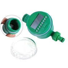 It all started with him. This was my first purchase on Aliexpress for the first automation at the dacha - I wanted to do automatic watering in the greenhouse. The timer came in a crumpled box, with a cracked protective cap, but working. He perfectly worked the entire summer season watering cucumbers. For the winter was removed and hidden in a warm and dry place. But the next season I had an unpleasant surprise - the timer began to hang, stopped responding to the control buttons and open the water. At first I sinned on cheap batteries and replaced them with branded Duracell. I thought the problem in power and inrush currents. Did not help. Then I took out a soldering iron and soldered everything in it, even added some missing capacitors. But he stubbornly continued to hang. Unfortunately, the product is not very maintainable - in the fact that I had used an unpackaged microcircuit-drop and, apparently, something was broken up just under the compound with the microcircuit. Somehow, the season was over with such a quirky timer and I started thinking about what to replace it with.
The first thoughts were to take the Arduino Mini module, the clock module, the indicator and somehow push it all into the body of the broken timer and activate its own motor and ball valve. But somehow it didn’t really go there, it would obviously consume more than the original filling (which means you can forget about the batteries in the case) and it was boring and not scalable - you only wanted to water the greenhouse, and only one broken timer.
And here on Ali I came across a normal motorized ball valve. Here is such a handsome man:

')
Yes, it cost a lot of money, but it was not scary to connect it with a summer water supply and leave it for a week without supervision. It is generally quite solid, albeit with a plastic gearbox - now a couple of such taps work on my main water supply, where the pressure is 5 atm.
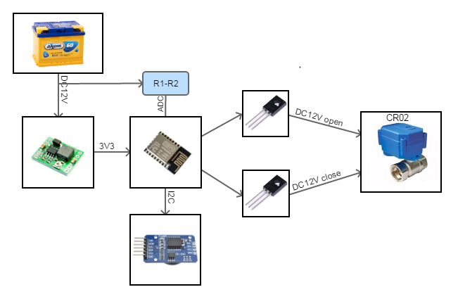
The idea was simple. In the drawer of the table, a handkerchief with an ESP8266 WiFi module was waiting in the wings It was decided to abandon power saving in favor of a used car battery, which, according to calculations, should have been enough for at least a month of autonomous operation of the device. . The DS3231 module with a battery was supposed to serve as clock for the circuit, and the kerchief per m / s MP1584EN should have reduced the voltage from 12V to 3.3V.
Here is the prototype block diagram:
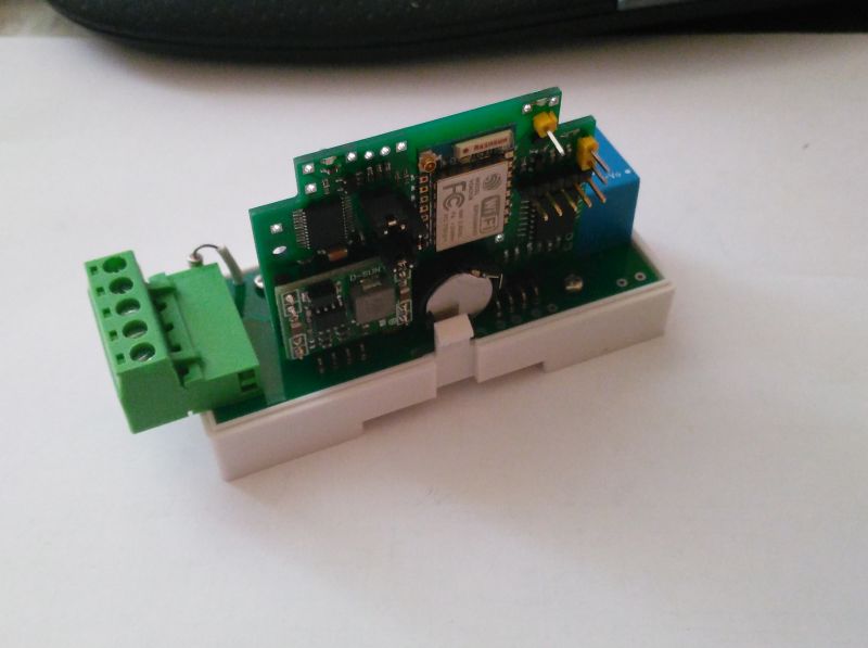
But the photo of its implementation
already slightly disassembled implementation - the DC-DC module went into the combat crane, the clock module on the back of the breadboard
already slightly disassembled implementation - the DC-DC module went into the combat crane, the clock module on the back of the breadboard
Controlling the motor of the crane here is done simply - what transistors were found in the drawer of the table, and set them. In reality, the motor can be controlled, for example, via m / s ULN2003 by switching on several channels in parallel or by field-effect transistors with logic control or, in general, through an opto-isolating relay module. It is only necessary to take into account that the motor with a working current of about 70mA, has a starting current (and the current at the time of rotation blocking) is about 300-350mA.
A sketch on Arduino with a simple web-interface would be quickly written:

And the prototype stood on test duty. I sent the web-interface of the crane through a router and the device was constantly available online.
And thoughts ran on. One prototype is good, but I want several of these cranes and doing it all on the breadboard is not an option. The crane was opened. And it became clear that inside there is a lot of space under the airtight lid and there are even mounting places:

In the crane that was used in the prototype, under the lid there was a small board with a relay that provided the control logic. And in the photo crane with an index CR05. There are no logic and circuit boards in these cranes. Just removed the motor control wires and wires limit switches. And to operate such cranes it is necessary to change the polarity of the voltage on the motor. In this case, it is highly desirable to control the closing / opening end moments by the end switches of the TC, we remember that the current at these moments is already 300-350 mA.
The block diagram has begun to emerge as follows:

Now we take in hand a caliper, a sheet of paper and begin to take measurements, draw the outline of the printed circuit board and try to place components on it. From a large battery CR2032 went to refuse and apply a small CR1220 (or 1225). For a very long time, the N-bridge microcircuit was selected to control the motor. The choice seems to be big, but a lot of these microcircuits either cannot work at a supply voltage of 12V, or use bipolar transistors with a very large voltage drop, well, or the casing is unsuccessful. At first, the TB6612 microcircuit didn’t come across for a long time, and then it seemed very redundant and inconvenient for soldering. But in the end he stopped on her - she is affordable and inexpensive on Ali. The H-bridge is built on field-effect transistors and can operate at voltages up to 15 volts. The DC-DC converter module (MP1584EN) was left by the module - it turned out to be just cheaper in parts and it was easy to unsolder it. The main thing for reliability is to replace the voltage trimmer with a constant voltage (27kOhm - it will give an output voltage of 3.4V). The clock chip could be used in a more compact package, but there was one nuance - I was going to order all the components for Ali and there was a risk to get fake or non-working chips. Therefore, at the initial stage, all the chips were planned to be purchased as part of ready-made modules and re-soldered to the developed board. And in the watch modules were only in the case of SO16. In fact, only one microcircuit of the clock turned out to be a marriage or a bad fake - the frequency of the quartz was 32727 at the required 32768 kHz.
After all the preparatory work, we take KiKad, google a little in search of the missing seats, draw some components ourselves and start to make a fee:

Check it out, printing at a scale of 1: 1. We attach parts and modules and, if everything is the same, prepare Gerber files for production and send them to EasyEda. After 3 weeks we get 10 cute handkerchiefs and collect them.

There are 5 left in the photo, the rest all work

Module assembly
Holes for fasteners, of course, didn’t coincide a bit, some of the seats didn’t look like they wanted, but on the whole the product, after assembly and firmware, worked right away. On Ali, hermetic tails of power were bought, passed through a regular pressure seal in the housing, and the WiFi timer-crane acquired the finished factory look:

Here are a couple of cranes on combat duty at the cottage:
at the post
But then the thought again ran on. I wanted more automation at the dacha, and the module turned out to be quite compact and versatile. Through the H-bridge it is quite possible to control a conventional relay. For DIY automation, many take Sonoff, and then it turns out that I myself can do no worse.
And here begins the transformation of a simple Wi-Fi tap into what has been code-named SHAPEsp , short for Esp 8266 based S Mart H ome Automation P latform. As planned, this should be an inexpensive universal module for home automation. And all this should be reliable and look like a complete product after assembly into an affordable case.
It's an amazing thing, but it turned out that the Chinese case with Aliexpress to 2DIN unit is fine, the plug is in the plug, the popular AC / DC converter 220V / 12V HiLink (well, or its clone), the relay and the power connector fits, and of course my slightly over-diluted module ESP8266, clock and h-bridge.
Do it once
Make two
Do three
the module can be installed both in the crane body and in the DIN-rail body
the module can be installed both in the crane body and in the DIN-rail body
And we get:
Slightly changed the form of the module. I added edge connectors to it so that it could just stand upright in a 2DIN case. Placed on the upper end of the board indicator LEDs that are visible on the lumen in a plastic case. Well, I spread the carrier board for the relay and the power supply. To make it cheaper, all this was sent to the production of a single board:

I collected two such prototypes and put them in the country to manage the inclusion of convectors for winter raids:
In another post
One of the modules in the panel, next to a pair of contactors that include convectors
One of the modules in the panel, next to a pair of contactors that include convectors
But then he decided to further improve it and make it more universal. For a more reliable and convenient firmware posted on the module firmware from NodeMcu. He removed all possible pins and added contact pads for the convenience of connecting different sensors. All edge pins are placed in 2.54mm increments, so the module can be plugged into the breadboard breadboard. Naturally I tried connecting the ds1820 thermometer, the combined BME280 sensor and the humidity sensor on the comparator. It turned out that, in addition to a simple timer with a relay or a crane, you can easily build a weather station or, for example, an aquastop system. Well, all other notification systems and management ...
Carried away, I drew a model for my Fritzing module. So you can evaluate and rotate the various applications virtually:

The link to the GitHub model is at the bottom of the article.
And then the most difficult part begins - software support for the module. Initially, I tested and tested everything with my rather simple Arduino-sketch. Simple HTML, a little java script, various simple ways to transfer data, only the functionality of the timer and some sensors I need. But it quickly became clear that mastering everything and everyone in the modern world of IoT and smart housing will not be so easy. And also just laziness (there is a smiling smiley). And sometimes you do not want to reinvent the wheel.
Therefore, it was decided to see what is of the ready firmware in which you can add support for your module. As a starting point, alternative firmware for Sonoff products were taken: Sonoff-Tasmota, ESPurna, ESPEasy. Search you can find comparative reviews of these firmware.
For example:
https://lobradov.imtqy.com/FOSS-Firmware-comparison-overview/
https://lobradov.imtqy.com/FOSS-Firmware-comparison-developers/
In reality, I somehow ran my eyes with the source texts in the repositories of these firmware, I realized that it would be easier for me to add my module to the ESPurna firmware. The firmware code was quite reasonably structured and initially assumed the addition of new modules and functions. The firmware required me the timer functionality — the autonomous Sheduler. Moreover, it can be said out of the box, just by describing my configuration with a simple relay in the file hardware.h, I got the working version of the WiFi relay firmware.
However, my module had richer and more complex functionality. And it was decided to contribute to the firmware. On the one hand, this is quite simple - we write the functionality and make a pull request, but in reality this is a tedious and lengthy process with not always a positive or quick result. These are the costs of the fact that the proposed functionality is by and large only needed by me and my unknown motherboard.
I started with the support of hours. In ESPurna firmware, everything worked through NTP and the Time library for arduino - well, it so happened that you need to know the time, while Sonoff products do not have autonomous clocks and it is assumed that they always have access to the Internet. To support RTC hours, I wrote a simple module that, if desired, replaced the function of the time provider from pure NTP to NTP + RTC. The principle was simple - if NTP synchronization is not available, then we are trying to read the time from the local RTC clock. When access to NTP servers appears, restore synchronization and, if desired, synchronize the local clock. So the clock on my module got involved. Pull-request fairly quickly accepted, but he laid down in a separate branch of espurna-rtc.
Next was a trivial pull request. Since I measure the supply voltage to the DC-DC converter in order to track the discharge of the battery, I did not need to monitor the supply voltage of the ESP8266 module, but of some user. What I designed as a pull request “add support for custom VCC monitoring”. But this request somehow hung in the air ... and the desire to contribute somehow subsided.
In addition, it became obvious that it would not be so easy to add your module to the list of supported finished devices - it can have a lot of different configurations. Therefore, it was decided to simply develop your fork firmware. And if possible, and if you wish, you can maintain synchronization, make pull-requests or offer cherry-pick to the main firmware repository.
After such a decision, everything became easier. In the firmware, the relay control system was partially rewritten. The H-bridge control mode has been added to it and it has become more convenient in terms of adding custom relay operation modes.
Further study of the firmware code showed that its refactor is not to refactor. The style of writing and use of resources in some places is very tough for the microcontroller (although it is rather smart 32-bit). For example, the system of issuing debugging messages devoured the stack at a tremendous speed, but at the same time, in order not to drop the entire system, it was blocked when the stack size was less than 10 kB. I rewrote the code a bit in my branch so now all the debug messages and hints in the console are displayed completely.
Well, at the moment, the calculation subsystem has been added to the firmware
sunrises / sunsets and a virtual sensor SunriseSensor, so you can build a simple astronomical relay from the SHAPEsp module. It will be necessary to collect the spirit and commit to the main repository. I think this is a useful feature.
This is the story of the transformation of DIY ideas from prototype to almost finished product. Possibly claimed product. Most surprisingly, I have not yet tried any smart home systems - all modules work for me completely autonomously from each other and are simply accessible via web interfaces on the Internet. A once-bought OrangePi PC board lies in a drawer and waits in the wings to become a smart home controller.
List of links:
Source: https://habr.com/ru/post/422435/
All Articles