ESP8266 + FLProg - Custom system settings and time server synchronization

In this lesson we will look at the use of user-defined system variables for connecting a web-based configuration interface and a project schema. We will also try to configure the synchronization of the system clock of the controller with the servers of the exact time.
This lesson is created for version 3.1.4, which is now in pre-release testing. Download it here . For more information about the project FLProg can be found in the company's blog on Habré , the project site and forum . In addition to the channel ArduinoProm you can watch a huge variety of video lessons.
As a basis, we will use a project created in the past lesson .
')
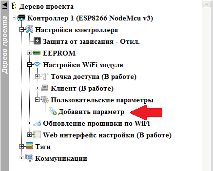
To begin with, we will create in three system user parameters in which the current system time of the controller will be stored, the time zone, and the address of the exact time server with which we will synchronize. To do this, we find the “ Add Parameter ” branch in the project tree in the “ User Parameters ” node.
A dialog box for adding a new system parameter will open. Fill it up.
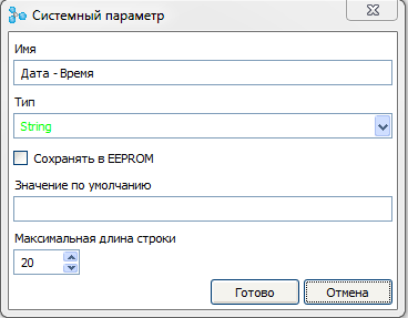
In the “ Name ” field, enter the name of the parameter. Select the type of the parameter - “ String ”. The value of this parameter will be dynamically changed during operation, therefore, disable saving the parameter value in the EEPROM. Therefore, do not set the default value. The maximum length of the string is 20 (the output will be in the form 01:01:01 01-01-2018, that is, 19 characters).
In the same way, add the second parameter

Just leave the save in the EEPROM, so that the controller remembers the server we entered, and set the default server.
Finally, create a third parameter, the time zone value, for the correct time display.
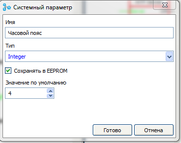
The type of the parameter Integer . It is necessary to save in the EEPROM, the default value of your choice (I have 4 hours).
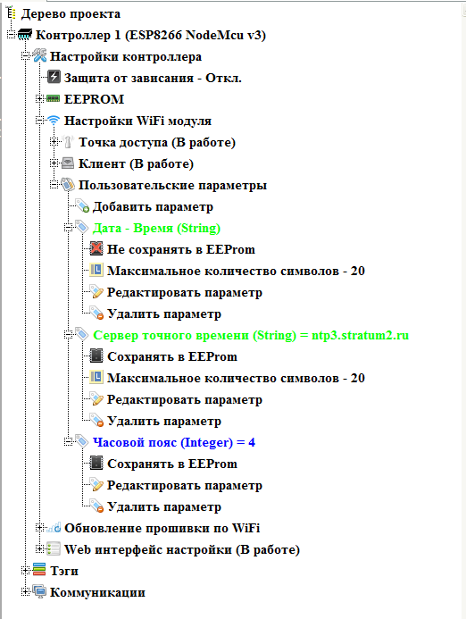
As a result, we got three user parameters.
We proceed to the firmware layout.
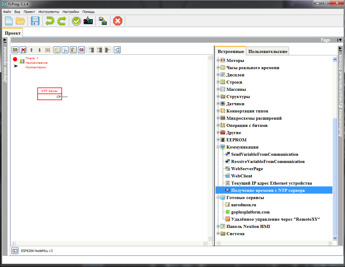
In the library of functional blocks we find the block “ Getting time from the NTP server ” and drag it onto the workspace of the scheme
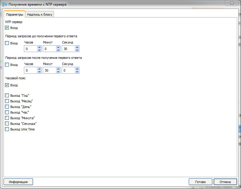
Double click on this block opens the block parameter editor.

Consider the settings in more detail.
NTP server - server address from which the exact time will be taken. Can be set as a constant. You can choose from the list of standard. I checked everything - they work. Click the “ Standard Servers ” button to select.

But since we want “ by adult ” to set the server address from the web interface, we tick the check box “ Login ”
The request period prior to receiving the first response is the frequency with which the controller will “ knock ” on the server until it receives time for the first time. We leave the constant value every 30 seconds. It is also possible to set the input, then it will be necessary to feed the value in milliseconds.
Request period after receiving the first response - how often the controller will check the time at the server. We leave by default once every half hour. You can also set via the input, in milliseconds.
Time zone - Since the server gives time according to GMT, this parameter sets the time zone offset in hours. We decided to set this parameter through the web interface, so we tick the checkbox “ Login ”
Exit “Year” , Exit “Month” , Exit “Day” , Exit “Hour” , Exit “Minute” , Exit “Second” - we do not need them in this lesson, therefore we do not set ticks.
Exit “Unix Time” - we don’t need this exit, we don’t put a tick (to be honest, I haven’t yet come up with a User Case for it. But just in case, I’d need someone to use it).
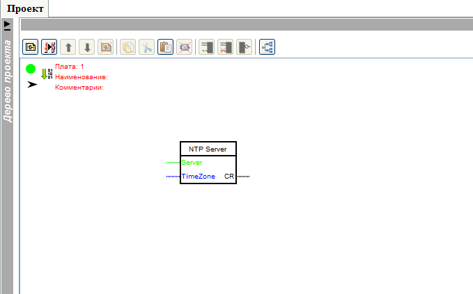
So we got this block setting
The block on the firmware layout has changed accordingly.
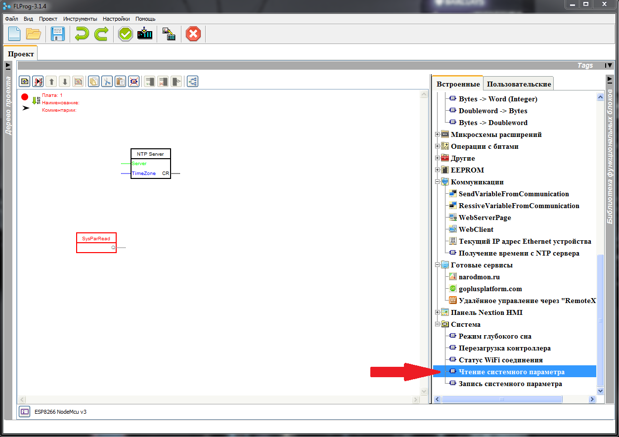
Find the “ Read system parameter ” block in the library and drag it onto the schematic.
Double click on this block, and begin to adjust its parameters.
First, press the system parameter selection button.

The system parameter selection window opens. Select the option “ Time server ”

This completes the block setup.
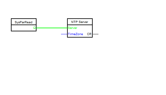
We conveniently arrange the blocks and connect the output of the “ Read system parameter ” block to the “ Server ” input of the “ Get time from NTP server ” block
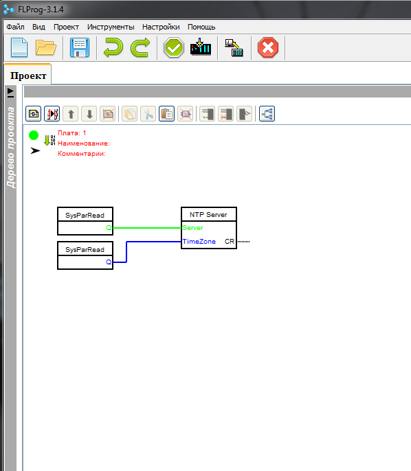
Drag and drop one more “ Reading system parameter ” block onto the scheme and set it to read the “ Time Zone ” parameter.

We connect the output of this block to the “ TimeZone ” input of the “ Getting time from NTP server ” block
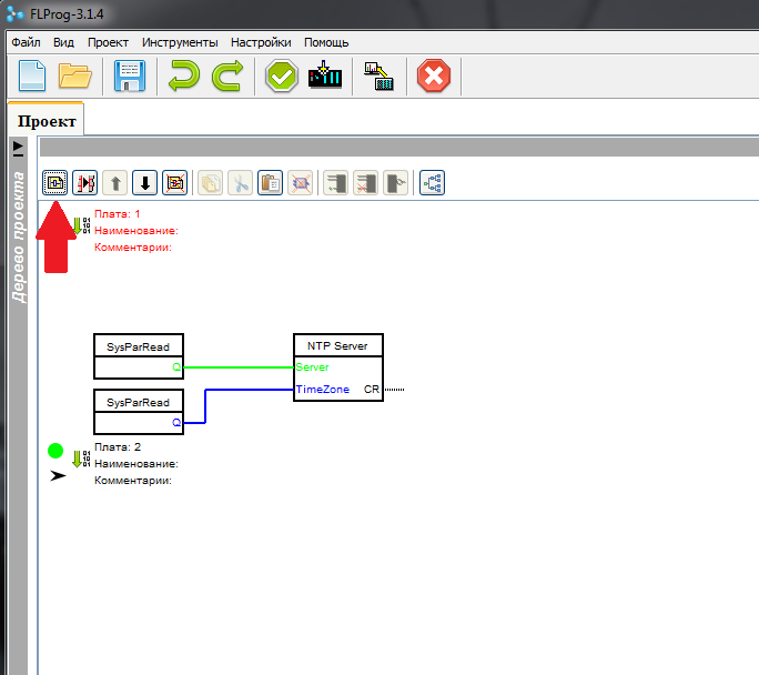
Add a new board to the scheme. To do this, click the button " Add fee "
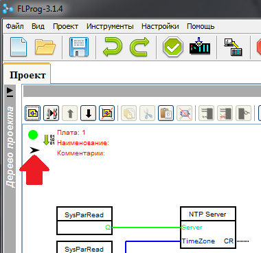
We turn off the first payment, we will not need it anymore. To do this, click on the arrow in the header of the first board.
We pull out the block “ Data acquisition from the clock of the exact time ” to the second board
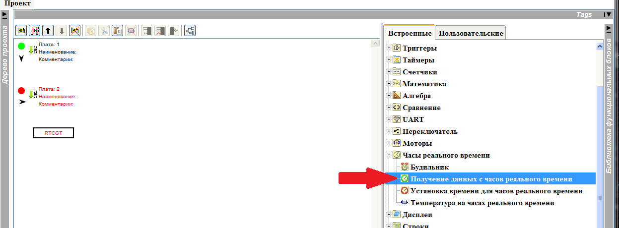
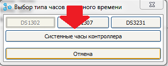
Double click on it to call the block setup dialog. Pressing the “ New ” button, we open the clock selection dialog and select the “ System controller clock ”.

Then put a tick “ Exit“ Watch ” ”

And we finish editing the block.
Then we copy this block five more times, rearranging in the settings of each of them the checkbox of the output in the sequence Minute - Second - Day - Month - Year .

Now we pull out the “ String Conversion ” block from the library.
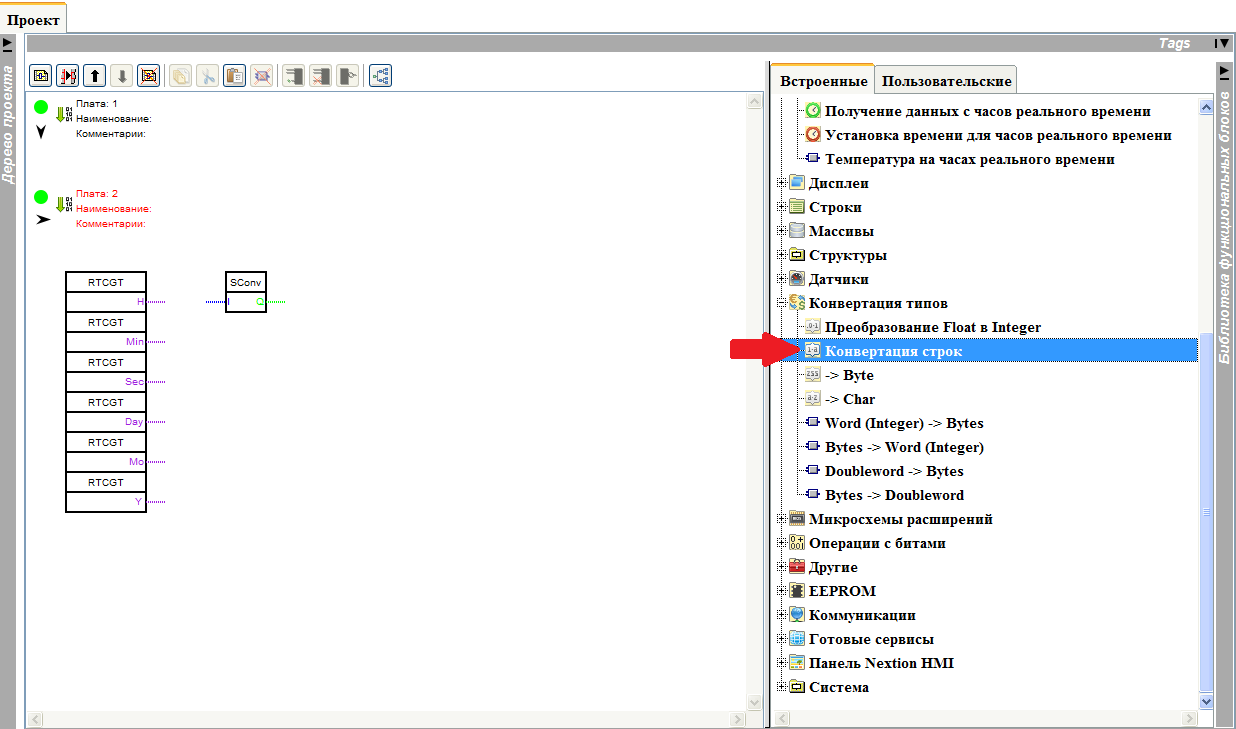
And in its settings, select the type of conversion “ Time ”

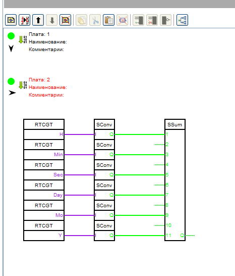
Copy the block five more times, and collect the scheme

Transferring the “ Addition of Strings ” block to the scheme from the library

In the block settings, set 11 inputs.

And connect the blocks according to the scheme
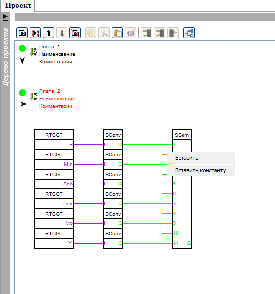
Set the constants on the free inputs of a block.
Input 2 - “:”
Login 4 - “:”
Input 6 - Space
Sign 8 - “-”
Input 10 - “-”
To set a constant, right-click on a free entry and select “ Insert Constant ” from the pop-up menu.
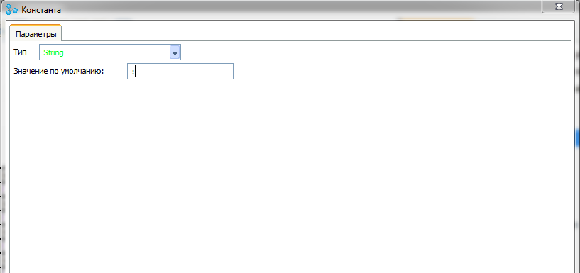
A constant input window opens, where the desired constant is entered in the “ Default Value ” field.
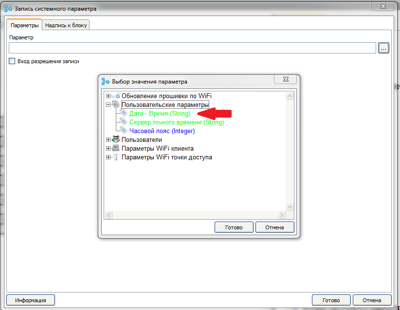
Now we pull out from the library the “ Record of system parameter ” block on the scheme

In the block settings, uncheck the “ Record entry input ” checkbox and select the “ Date - Time ” parameter
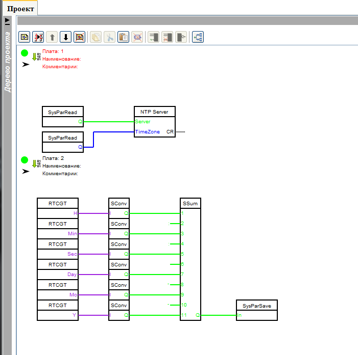
We connect the output of the block “ Addition of lines ” with the input of the block “ Record system parameter ”

As a result, we should have such a scheme (For clarity, we will deploy the first board).
With the firmware scheme finished, we return to the project tree.
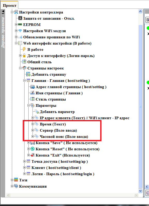
We will add three parameters to the main page of the Web interface (see how to do this in the previous lesson ).
Parameter 1 - System parameter “ Date - Time ”, parameter type - “ Text ”, label - “ Time ”
Parameter 2 - System parameter “ Time server ”, parameter type - “ Input field ”, label - “ Server ”
Parameter 3 - System parameter “ Time zone ”, parameter type - “ Input field ”, label - “ Time zone ”
Turn on the “ Save ” button on the page

Fill the program in the controller, and see what we did on the main page (how to do this, see the previous lesson )
Immediately after connecting - not yet synchronized with the time server
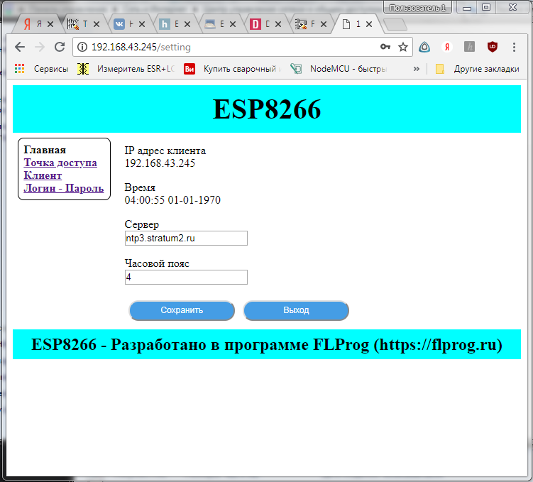
In a minute (the page was updated) - synchronization passed

Changed the time zone and clicked save

The project created in the lesson can be downloaded here .
Source: https://habr.com/ru/post/422377/
All Articles