Why the Arduino is so slow and what can be done about it
A long time ago I came across an excellent article ( tyk ) - in it the author quite clearly showed the difference between using Arduin functions and working with registers. There are a lot of articles, both praising Arduino and claiming that this is not serious and in general for children, so we will not repeat, but try to understand what caused the results obtained by the author of that article. And, no less important, we will think about what can be done. All who are interested, please under the cat.
Part 1 "Questions"
Quoting the author of this article:
It turns out the loss of performance in this case - 28 times. Of course, this does not mean that Arduino is 28 times slower, but I think that for clarity, this is the best example of what they do not like Arduino.
Since the article has just begun, we will not understand yet, but ignore the second sentence and assume that the speed of the controller is approximately equivalent to the pin switching frequency. Those. we are faced with the task of making the generator of the greatest frequency from what we have. First, let's see how bad everything is.
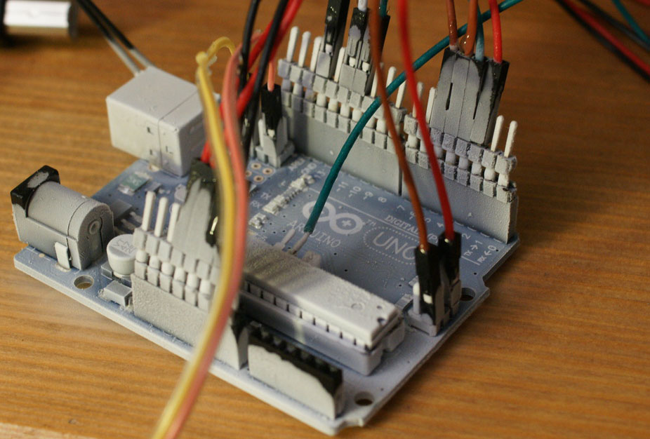
Let's write a simple program for arduino (in fact, just copy blink).
void setup() { pinMode(13, OUTPUT); } void loop() { digitalWrite(13, 1); // turn the LED on (HIGH is the voltage level) digitalWrite(13, 0); // turn the LED off by making the voltage LOW } We sew in the controller. Since I do not have an oscilloscope, but only a Chinese logic analyzer, it must be properly configured. The maximum frequency of the analyzer is 24 MHz, therefore it must be equalized with the frequency of the controller - set to 16MHz. We look ...
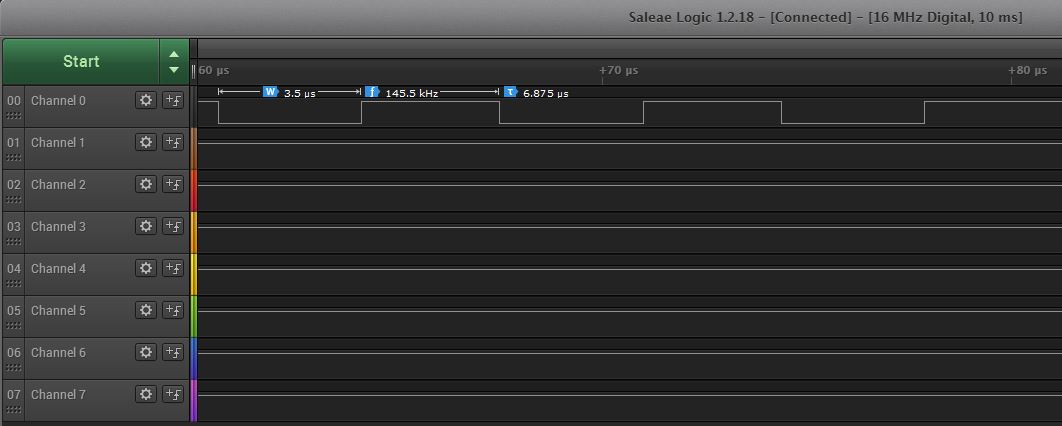
... for a long time. We are trying to remember what determines the speed of the controller - exactly, the frequency. We look in arduino.cc . Clock Speed is 16 MHz, and we have 145.5 kHz here. What to do? Let's try to solve it in the forehead. On the same arduino.cc we look at the other boards:
- Leonardo - will not work - there is also 16 MHz
- Mega - also - 16 MHz
- 101 - suitable - 32MHz
- DUE - even better - 84 MHz
We can assume that if you increase the frequency of the controller by 2 times, then the flashing frequency of the LED will also increase by 2 times, and if by 5, then by 5 times.

We did not get the desired results. And the generator is less and less like a meander. We think further - now, probably, the language is bad. It seems like there is a s, s ++, but it is difficult (in accordance with the Dunning-Kruger effect, we cannot realize what we are already writing in s ++), therefore we are looking for alternatives. Short searches lead us to BASCOM-AVR (it is well described here), set, write code:
$Regfile="m328pdef.dat" $Crystal=16000000 Config Portb.5 = Output Do Toggle Portb.5 Loop We get:
The result is much better, besides, an ideal meander has turned out, but ... a basic in 2018m, seriously? Perhaps we leave it in the past.
Part 2 "Answers"
It seems, it is time to stop fooling around and start to understand (and also remember the C and assembler). Just copy the "useful" code from the article mentioned at the beginning into loop ().
Here, I believe, we need an explanation: all the code will be written in the Arduino project, but in Atmel Studio 7.0 (there is a convenient disassembler), the screens will come from it.
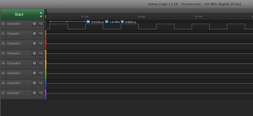
void setup() { DDRB |= (1 << 5); // PB5 } void loop() { PORTB &= ~(1 << 5); //OFF PORTB |= (1 << 5); //ON } result:
Here it is! Almost what you need. Only the form is not particularly similar to the meander and the frequency, although closer, but still not the same. We will also try to zoom in and detect breaks in the signal every millisecond.

This is due to the triggering of interrupts from the timer responsible for millis (). So let's just turn it off. We are looking for ISR (function interrupt handler). Find:
ISR(TIMER0_OVF_vect) { // copy these to local variables so they can be stored in registers // (volatile variables must be read from memory on every access) unsigned long m = timer0_millis; nsigned char f = timer0_fract; m += MILLIS_INC; f += FRACT_INC; if (f >= FRACT_MAX) { f -= FRACT_MAX; m += 1; } timer0_fract = f; timer0_millis = m; timer0_overflow_count++; } A lot of useless code for us. You can change the timer mode or disable the interrupt, but this is unnecessary for our purposes, so we simply disable all interrupts with the cli () command. Just look at our code:
PORTB &= ~(1 << 5); //OFF PORTB |= (1 << 5); //ON too many operators, reduce to one assignment.
PORTB = 0b00000000; //OFF PORTB = 0b11111111; //ON And the transition to loop () takes a lot of commands, since this is an extra function in the main loop.
int main(void) { init(); // ... setup(); for (;;) { loop(); if (serialEventRun) serialEventRun(); } return 0; } So just make an infinite loop in setup (). We get the following:
void setup() { cli(); DDRB |= (1 << 5); // PB5 while (1) { PORTB = 0b00000000; //OFF PORTB = 0b11111111; //ON } } 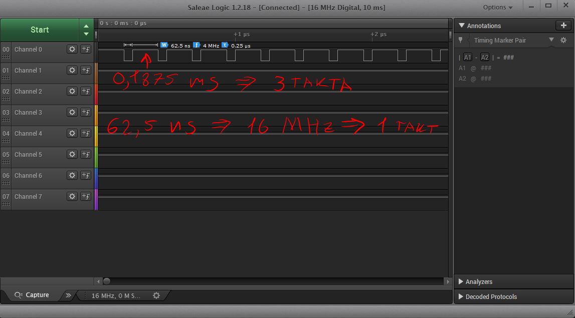
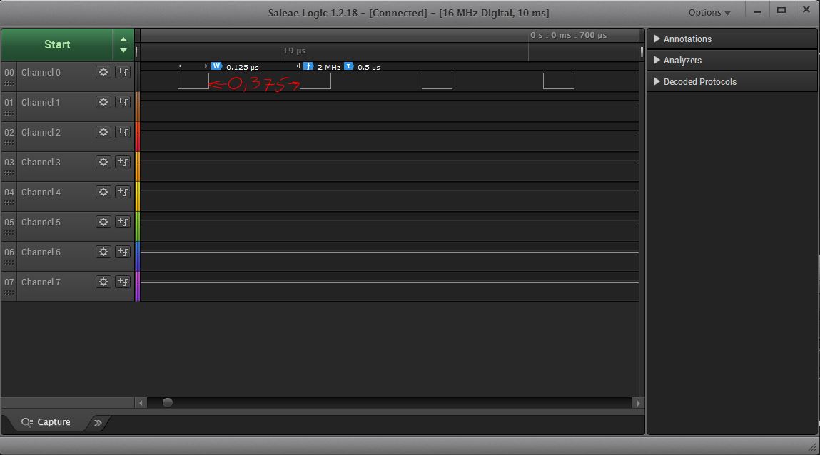
61 ns is the maximum corresponding to the frequency of the controller. Is it possible faster? Spoiler - no. Let's try to understand why - for this we disassemble our code:
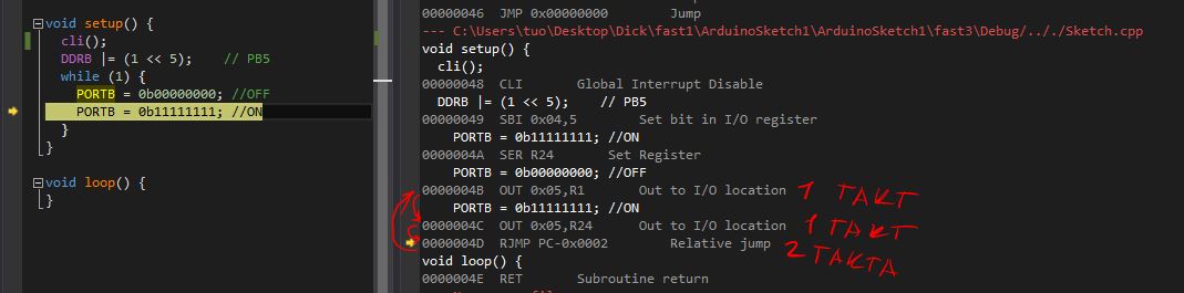
As can be seen from the screen, in order to write to port 1 or 0 exactly 1 clock is spent, only a transition goes further, which cannot be performed in less than one clock cycle (RJMP is performed in two clock cycles, and, for example, JMP, in three ). And we are practically at the goal - in order to get the meander, it is necessary to increase the time when 0 is given, by two measures. Add for this two assembler commands nop, which do nothing, but take 1 clock:
void setup() { cli(); DDRB |= (1 << 5); // PB5 while (1) { PORTB = 0b00000000; //OFF asm("nop"); asm("nop"); PORTB = 0b11111111; //ON } } 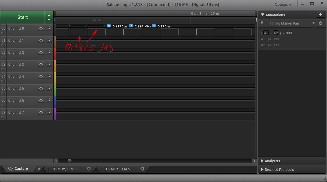
Part 3 "Conclusions"
Unfortunately, everything we did was absolutely useless from a practical point of view, because we can no longer execute any code. Also in 99.9% of cases, the frequency of switching ports is enough for any purpose. And if we really need to generate a flat meander, we can take stm32 with dma or an external timer chip like NE555. This article is useful for understanding the structure of the mega328p and arduino in general.
However, writing registers to 8-bit values PORTB = 0b11111111; much faster than digitalWrite(13, 1); but you have to pay for this by the impossibility of transferring the code to other cards, because the names of the registers may differ.
There remains only one question: why the use of faster stones did not produce results? The answer is very simple - in complex systems, the gpio frequency is lower than the core frequency. But how much lower and how to set it up can always be seen in the datasheet on a specific controller.
The publication referred to the articles:
- HWman https://habr.com/post/254163/
- vvzvlad https://habr.com/post/151544/
- Datam ATmega328 / P
- Of course https://arduino.cc
- Preview https://habr.com/post/190180/
')
Source: https://habr.com/ru/post/422177/
All Articles