Developing a video converter from 264 to avi for the QCM-08DL dashcam
In fact, the article is devoted to the development of a program for repacking a DVR video from one container to another, if this can be called a conversion. Although, all my life I believed that the converter is engaged in the conversion (recoding) of the video format. This article is the second part of my previous publication, where I talked in detail about access to all video recorders of the DVR. But at the very beginning of the publication I set another task: to study the algorithm that the regular 264-avi repackaging program works on and create the same program that would perform the same operations, but not on one, but on a whole group of files, and "One click".
Let me explain once again the essence of all things in simple language.
The user has a DVR, for example, the popular model QCM-08DL. He needs a video for a certain date and time. He can extract it either to a USB flash drive or via a DVR web interface to a computer. The extracted video file (extension .264) will open only in the player program that came with the DVR. The player is very uncomfortable. It can also be opened in the VLC player by setting the RAW H264 mode in the demultiplexing settings (settings for advanced users). But at the same time, blocks of audio streams, which are interpreted as video, interfere with normal playback, but there is no soundtrack. And in order to open a video in any player, the .264 file must first be converted to some popular format, for example, avi. A conversion program is also included with the DVR. But she is also very uncomfortable. When it comes to one or more files, there are no problems. However, when the task is to get access to all the videos on the hard disk, and even more so to convert them all into a popular format, the standard toolkit is practically not suitable.

')
The task of access to all files solved. This was the subject of the last publication. We proceed to the solution of the second problem. I have already been given "practical advice": it is enough to rename the extension from "264" to "avi" in the file name, and everything will trample, they say, there is nothing to bother with. But this is the most common mistake of any ordinary user, who, as a rule, does not understand the relevant issues.
In the last publication I already wrote briefly about the structure of the source file. 264. I will remind you.
Basic information from audio and video streams begins at an offset of 65,536 bytes. Blocks of a video stream begin with an 8-byte header “01dcH264” (there is also “00dcH264”). The following 4 bytes describe the size of the current block of the video stream in bytes. After 4 bytes of zeros (00 00 00 00) the video stream block itself begins. Blocks of audio streams have the header “03wb” (although, according to my observations, the first character of the header in some cases was not necessarily “0”). After - 12 bytes of information, which I have not yet divined. And starting from the 17th byte - a fixed-length audio stream of 160 bytes. There are no tags at the end of the file.
I will comment on the foregoing. Everything that is before the offset of 65536 bytes, turned out to be unsolved and unnecessary. From the offset of 65536 bytes to the first header of the stream there is a small gap, the contents of which are also not solved, and, moreover, as I checked, it is not found in the output avi file after conversion by a regular program.
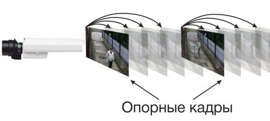
Each block of the video stream is one frame. The first character in the block header of the video stream is optional "0". I did not guess his purpose, because, as I found out, it is not the key to solving the task. The second character of the video stream header can be either “1” or “0”. In the second case, the content of the video stream block is the so-called reference frame. And in the first case, the content of the video stream block is an encoded compressed frame, which depends on the reference frame. The size of the contents of the reference frame is much larger than the size of the contents of the compressed auxiliary frame. The repetition period of the reference frames most likely depends on the settings for the compression ratio in the DVR. But in my case, the repetition period was 1 frame / sec.
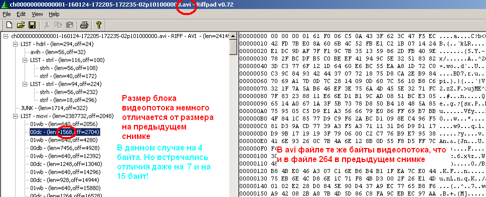
The standard program for repacking video from the “264” container into the “avi” container gave different results regarding the frame rate. In the case of videos that were recorded in high resolution mode (704 * 576), the frame rate was 20 frames / sec. And in the case of low resolution (352 * 288) - 25 frames / sec. This information is provided by the MediaInfo utility. It also shows that the video size is the same for any case: 720 * 576, and the size of the video stream (the same utility reports) is 704 * 576 or 352 * 288. Most players are deployed precisely under the size of the video stream. However, I met a player that incorrectly displayed a half-screen mode when playing a 352 * 288 file. I wanted to correct this minor flaw in the staff repacker by looking at the bytes of the content of the video stream and pulling out the frame size information from there. But in a hurry, I could not do it. The above is illustrated in the figure below.

Now about the frame rate. As I found out, the regular repacker does not refer to any header field of the “264” container. He judges the frame rate by calculating the ratio of the number of video blocks and audio streams. And this value is not even rounded to the integer value when calculating, as can be seen from the figure above (circled in green). As I found out, the number of blocks of an audio stream per unit of time is always and everywhere (in any file) fixed, namely, 25 blocks per second. If you examine a video file with a frequency of 20 frames / sec., Then the reference frame (block) is encountered every 19 compressed frames, and for the case of 25 frames / sec. - every 24 compressed frames.
We will continue to study the structure of the video stream header. We figured out the first eight bytes: this is the label of the reference or compressed frame plus the keyword "H264". The next four bytes describe, as I found out, not the exact, but the approximate size of the contents of the video stream. A regular repacker transfers all the bytes of this content completely, and then the resulting size is written into the corresponding fields of the avi-container. And this value is different from the value specified in the corresponding field of the original .264 file.
Twelve bytes of information after the block header of the audio stream, I partially guessed. In any case, the key elements are the last 4 bytes, after which the audio stream begins. These are two 16-bit numbers that describe the initial parameters of the iterative decoding scheme from ADPCM to PCM. Decoding increases the size of the audio stream by 4 times. I found out in advance, after a detailed examination of the files, that the regular repacker decodes audio, but leaves the video content unchanged.
Having no deep knowledge, for a long time I tried to figure out exactly which decoding algorithm was used in my case. Intuitively, I already guessed that the ADPCM compression method was used. More precisely, not intuitively, but with a competent approach, based on the fact that the audio stream is compressed exactly 4 times. And when opening a fragment in Adobe Audition as RAW in various formats (and comparing the same fragment after repacking with a regular program), the ADPCM gave me a very similar (but not exact) sound result. Information on the wiki.multimedia.cx/index.php/IMA_ADPCM website helped me to parse the compression algorithm. Here I learned about the two initial decoding parameters, and then, using the “spear method,” I guessed that these initial parameters were recorded in 4 bytes before the beginning of the audio stream. I will describe the work of the algorithm and give a rough mathematical interpretation (under the spoiler).
We now turn to the description of the structure of the avi container. In fact, it is a complex hierarchical structure.
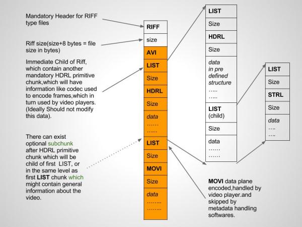
But, simplifying the task for a particular case, I presented the avi structure in a linear form. The result was this: the avi file consists of a large header, zero byte skips (JUNK), audio and video streams (with their headers and content sizes), and a list of indexes. The latter serves, in particular, to scroll through the video in the player. Without this list scrolling will not work (checked). It is only a table of contents, which lists the key names of the flow blocks (matching the names in the block headers), the corresponding size of the content and the values of the offsets (addresses) relative to the beginning of the flow area.
Now you can go to the development of the program. The specific description of the problem is as follows.
At the root of section X: there is a “DVR” directory. This directory contains many non-empty subdirectories (and only subdirectories) with names that correspond to certain dates. In each of these subdirectories there are many files with different names and the extension "264". Required in section Y: create a directory "DVR", and in it the same subdirectories as in section X :. Each of such subdirectories should be filled with files with the same corresponding names, but with the extensions not “264”, but “avi”. These avi-files need to be obtained from the original 264-files by processing them, which, one way or another, repeats the algorithm of an existing program. Processing consists of direct repacking of video streams, repacking with decoding of audio streams, formatting the avi file. The program should be launched from the command line as follows: "264toavi.exe X: Y:", where "264toavi.exe" is the name of the program, "X:" is the source section, "Y:" is the destination section.
In fact, to simplify the task, you could write a program that would only deal with the conversion (repacking) of a single file, making the day two arguments: the name of the input file and the name of the output file. And then, in order to implement group repacking, you can write a command batch file (bat) using other tools, for example, Excel. But I implemented a full-fledged program, very cumbersome. It is unlikely that the source code would have earned the attention of readers. I will describe the structure of the program code.
The program is written in C language in the Dev-C ++ development environment with WinAPI elements. The program has three large auxiliary functions: the function of forming the original avi header, the function of decoding the audio sample and the function of scanning the source file "264" by words. Words I call a portion of 4 bytes. It was noted that the size of the headers and contents of all streams is a multiple of four bytes. The scan function can return five values: 0 - if it is the usual 4 bytes of the video stream for repacking, 1 - if it is the header of the video stream block of the reference frame, 2 - if it is the header of the video stream block of the compressed frame, 4 - if it is “Spoiled” block to be ignored when repacking. Very, very rare, but this is met. The corrupted block (as I called it) is a header of the form "\ 0 \ 0 \ 0 \ 0H264", where "\ 0" is a zero byte. Blocks of this type of regular repacker ignores. Of course, the contents of such a block may turn out to be quite working, but I ignore such blocks in order to make my program as close as possible to the standard one.
In the main function, in addition to organizing directories, the input file is read by the scan function. Depending on what this function returns, further actions occur. If these are the headers of the video streams, then the corresponding headers are formed into the output avi file. There they are called differently: “00db” is the header of the video stream block of the reference frame, and “00dc” is for the compressed frame. After the repacking operation (rewriting of words) before the new newly encountered header, the size of the repacked content is calculated and this value is written into the field that immediately follows the header of the stream just processed. If you encounter an audio stream header while scanning, the header name “03wb” is formed into the output avi file and the audio stream from ADPCM to PCM is decoded simultaneously in the loop while the decoded content is written to the avi file. Simultaneously with all of the above, the brief information (table of contents) is recorded in the temporary index file “index”. The scanning function could not be done, but all written in the main function. But then the program would have been very cumbersome and almost difficult to read.
At the end of the whole operation, when the input file “264” ended, before moving to the new file, the program correctly completes all the operations. First, certain fields in the avi file header are adjusted, the values of which depend on the size and number of streams read, and then the contents of the temporary “index” file is added to the almost finished avi file, which is then deleted. After these operations, the output avi file is ready to play.
While the program is running, a text visualization takes place on the command line, which displays the current directory, file, as well as the block number of the video stream that falls on the reference frame and the corresponding video time in minutes and seconds. And if the input file has not an arbitrary name, but the source one (containing the channel number, the date and time of the start of the recording), then a more interactive visualization takes place, based on date-time arithmetic.
When testing and debugging the program, the main problems I had when working with audio decoding. Simple arithmetic worked incorrectly if I, when declaring variables in the decoding function, illiterately set types. Because of this, some blocks of audio streams were broken, and there were clicks on the ear. Some not completely clear fields of the header of the source file 264, which I could not guess, turned out to be insensitive to the result. Unlike the standard program, my program does not throw out the last incomplete flow block from the repack operation. Although his absence will not play any practical role. Another regular program, unlike mine, leaves behind a "garbage" in a small amount (this is the contents of the last stream) at the very end of the avi file after the indices. With all this, the video is played almost equally. A repacking program performs for the same period of time as the regular program.
In conclusion, I will give illustrations showing the structure of the organization of streams in a .264 file (in the WinHex hexadecimal editor) with an example of one of the files and a view of the RiffPad program with the avi file repacked open in it. This program has greatly simplified the process of studying the structure of an avi file. It clearly demonstrates the hierarchical structure, shows the byte content of each member of the structure, and even cleverly interprets the contents of the headers as a list of parameters. The picture, in particular, demonstrates the fact that the contents of the video stream correspond with no changes.

Let me explain once again the essence of all things in simple language.
The user has a DVR, for example, the popular model QCM-08DL. He needs a video for a certain date and time. He can extract it either to a USB flash drive or via a DVR web interface to a computer. The extracted video file (extension .264) will open only in the player program that came with the DVR. The player is very uncomfortable. It can also be opened in the VLC player by setting the RAW H264 mode in the demultiplexing settings (settings for advanced users). But at the same time, blocks of audio streams, which are interpreted as video, interfere with normal playback, but there is no soundtrack. And in order to open a video in any player, the .264 file must first be converted to some popular format, for example, avi. A conversion program is also included with the DVR. But she is also very uncomfortable. When it comes to one or more files, there are no problems. However, when the task is to get access to all the videos on the hard disk, and even more so to convert them all into a popular format, the standard toolkit is practically not suitable.
')
The task of access to all files solved. This was the subject of the last publication. We proceed to the solution of the second problem. I have already been given "practical advice": it is enough to rename the extension from "264" to "avi" in the file name, and everything will trample, they say, there is nothing to bother with. But this is the most common mistake of any ordinary user, who, as a rule, does not understand the relevant issues.
In the last publication I already wrote briefly about the structure of the source file. 264. I will remind you.
Basic information from audio and video streams begins at an offset of 65,536 bytes. Blocks of a video stream begin with an 8-byte header “01dcH264” (there is also “00dcH264”). The following 4 bytes describe the size of the current block of the video stream in bytes. After 4 bytes of zeros (00 00 00 00) the video stream block itself begins. Blocks of audio streams have the header “03wb” (although, according to my observations, the first character of the header in some cases was not necessarily “0”). After - 12 bytes of information, which I have not yet divined. And starting from the 17th byte - a fixed-length audio stream of 160 bytes. There are no tags at the end of the file.
I will comment on the foregoing. Everything that is before the offset of 65536 bytes, turned out to be unsolved and unnecessary. From the offset of 65536 bytes to the first header of the stream there is a small gap, the contents of which are also not solved, and, moreover, as I checked, it is not found in the output avi file after conversion by a regular program.
Each block of the video stream is one frame. The first character in the block header of the video stream is optional "0". I did not guess his purpose, because, as I found out, it is not the key to solving the task. The second character of the video stream header can be either “1” or “0”. In the second case, the content of the video stream block is the so-called reference frame. And in the first case, the content of the video stream block is an encoded compressed frame, which depends on the reference frame. The size of the contents of the reference frame is much larger than the size of the contents of the compressed auxiliary frame. The repetition period of the reference frames most likely depends on the settings for the compression ratio in the DVR. But in my case, the repetition period was 1 frame / sec.
The standard program for repacking video from the “264” container into the “avi” container gave different results regarding the frame rate. In the case of videos that were recorded in high resolution mode (704 * 576), the frame rate was 20 frames / sec. And in the case of low resolution (352 * 288) - 25 frames / sec. This information is provided by the MediaInfo utility. It also shows that the video size is the same for any case: 720 * 576, and the size of the video stream (the same utility reports) is 704 * 576 or 352 * 288. Most players are deployed precisely under the size of the video stream. However, I met a player that incorrectly displayed a half-screen mode when playing a 352 * 288 file. I wanted to correct this minor flaw in the staff repacker by looking at the bytes of the content of the video stream and pulling out the frame size information from there. But in a hurry, I could not do it. The above is illustrated in the figure below.
Now about the frame rate. As I found out, the regular repacker does not refer to any header field of the “264” container. He judges the frame rate by calculating the ratio of the number of video blocks and audio streams. And this value is not even rounded to the integer value when calculating, as can be seen from the figure above (circled in green). As I found out, the number of blocks of an audio stream per unit of time is always and everywhere (in any file) fixed, namely, 25 blocks per second. If you examine a video file with a frequency of 20 frames / sec., Then the reference frame (block) is encountered every 19 compressed frames, and for the case of 25 frames / sec. - every 24 compressed frames.
We will continue to study the structure of the video stream header. We figured out the first eight bytes: this is the label of the reference or compressed frame plus the keyword "H264". The next four bytes describe, as I found out, not the exact, but the approximate size of the contents of the video stream. A regular repacker transfers all the bytes of this content completely, and then the resulting size is written into the corresponding fields of the avi-container. And this value is different from the value specified in the corresponding field of the original .264 file.
Twelve bytes of information after the block header of the audio stream, I partially guessed. In any case, the key elements are the last 4 bytes, after which the audio stream begins. These are two 16-bit numbers that describe the initial parameters of the iterative decoding scheme from ADPCM to PCM. Decoding increases the size of the audio stream by 4 times. I found out in advance, after a detailed examination of the files, that the regular repacker decodes audio, but leaves the video content unchanged.
Having no deep knowledge, for a long time I tried to figure out exactly which decoding algorithm was used in my case. Intuitively, I already guessed that the ADPCM compression method was used. More precisely, not intuitively, but with a competent approach, based on the fact that the audio stream is compressed exactly 4 times. And when opening a fragment in Adobe Audition as RAW in various formats (and comparing the same fragment after repacking with a regular program), the ADPCM gave me a very similar (but not exact) sound result. Information on the wiki.multimedia.cx/index.php/IMA_ADPCM website helped me to parse the compression algorithm. Here I learned about the two initial decoding parameters, and then, using the “spear method,” I guessed that these initial parameters were recorded in 4 bytes before the beginning of the audio stream. I will describe the work of the algorithm and give a rough mathematical interpretation (under the spoiler).
Details of the ADPCM decoding algorithm
There is a sequence of samples. x0,x1,x2, dots. In addition, as already mentioned, there are two initial parameters y0 and s0 . Need to get a new sequence of samples y0,y1,y2 dots. . As you can already guess, the first output sample is already known: it coincides with one of the initial parameters. y0 . This is something other than “initial displacement”. It is worth noting that the input (source) samples are encoded with four bits. For sign types, integers from -8 to 7 inclusive are included in the encoding. The high bit is essentially responsible for the sign of the number. PCM output samples that are obtained after decoding have a sign 16-bit standard format.
Analyzing the code of the algorithm in C, you can see two tables. They are listed below.
These two “magic” arrays, one may say, are table functions, the arguments of which are substituted for the very two initial parameters, respectively. During the iteration process, with each step, the parameters are recalculated and substituted into these tables again. First, let's see how this is implemented in the code.
We declare necessary, including auxiliary variables.
Before the start of the iteration, you must assign the initial parameter to the variable current. y0 , and stepindex variable - s0 . This is done outside of the considered algorithm, so I do not reflect this code. This is followed by conversions that are performed in a circle (in a loop).
In the auxiliary step variable from the ima_step_table array, the value at the stepindex1 index is written. For the first iteration, this is the initial parameter. s0 For further iterations, this is a recalculated parameter. si . Then the value from this array is divided by 8 (apparently, completely) by the bit shift to the right, and the variable diff is initialized as a result of this division. Then, the three low-order bits of the input sample value are analyzed and, depending on their states, the diff variable can be corrected by three terms. The terms represent a similar integer division of the diff value by 4 (>> 2), by 2 (>> 1), or diff without changes (let it be the division by 1 for generalization). Then the most significant (sign) bit of the value of the input sample is analyzed. Depending on its state, the variable diff, which was formed before this, is added or subtracted to the variable current1. This will be the value of the output sample. For correctness, the values are limited above and below. Then stepindex1 is corrected by adding a value from the ima_index_table array to the index value of the input sample with a zero-bit sign bit. The values of stepindex1 are also subject to a limit. At the very end, before repeating this algorithm, the values of current and stepindex are assigned the values of current1 and stepindex1 just recalculated, and the algorithm is repeated anew.
You can try to figure out how to figure out how the diff variable is formed. Let be fi=f(si) . These are the values of the step variable at each i-th iteration step, as the value of the function (array) of the argument si where i=0,1,2, dots . For convenience, we denote the diff variable as d . Following the logic of the arguments described above, we have:
In the description of the formulas, I neglected the operations of restriction above and below. So, the iteration scheme looks like this:
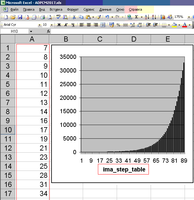
Deeply deep into the ADPCM coding / decoding theory I didn’t go into it. However, the table values of the ima_step_table array (out of 89 pieces), judging by their reflection on the graph (see the figure below), describe the probability distribution of samples relative to the zero line. In practice, it is usually this way: the closer the sample is to the zero line, the more frequent it is. Therefore, ADPCM is based on a probabilistic model, and far from any original set of 16-bit PCM samples can be correctly converted to 4-bit ADPCM samples. In general, ADPCM is a PCM with a variable quantization step. Apparently, this chart reflects this very variable step. He was chosen correctly, based on the law of distribution of audio data in practice.
Analyzing the code of the algorithm in C, you can see two tables. They are listed below.
int ima_index_table[] = { -1, -1, -1, -1, 2, 4, 6, 8 }; int ima_step_table[] = { 7, 8, 9, 10, 11, 12, 13, 14, 16, 17, 19, 21, 23, 25, 28, 31, 34, 37, 41, 45, 50, 55, 60, 66, 73, 80, 88, 97, 107, 118, 130, 143, 157, 173, 190, 209, 230, 253, 279, 307, 337, 371, 408, 449, 494, 544, 598, 658, 724, 796, 876, 963, 1060, 1166, 1282, 1411, 1552, 1707, 1878, 2066, 2272, 2499, 2749, 3024, 3327, 3660, 4026, 4428, 4871, 5358, 5894, 6484, 7132, 7845, 8630, 9493, 10442, 11487, 12635, 13899, 15289, 16818, 18500, 20350, 22385, 24623, 27086, 29794, 32767 }; These two “magic” arrays, one may say, are table functions, the arguments of which are substituted for the very two initial parameters, respectively. During the iteration process, with each step, the parameters are recalculated and substituted into these tables again. First, let's see how this is implemented in the code.
We declare necessary, including auxiliary variables.
int current1; int step; int stepindex1; int diff; int current; int stepindex; int value; // ; Before the start of the iteration, you must assign the initial parameter to the variable current. y0 , and stepindex variable - s0 . This is done outside of the considered algorithm, so I do not reflect this code. This is followed by conversions that are performed in a circle (in a loop).
value = read(input_sample); // ; current1 = current; stepindex1 = stepindex; step = ima_step_table[stepindex1]; diff = step>>3; if(value & 1){ diff += step >> 2; } if(value & 2){ diff += step >> 1; } if(value & 4){ diff += step; } if(value & 8){ current1 -= diff; if(current1 < -32768){ //, ""; current1 = -32768; } }else{ current1 += diff; if(current1 > 32767){ //, ""; current1 = 32767; } } // : current1; stepindex1 += ima_index_table[value & 7]; if(stepindex1 < 0){ // ""; stepindex1 = 0; } if(stepindex1 > 88){ // ""; stepindex1 = 88; } output_sample = curent1; // ; current = current1; stepindex = stepindex1; In the auxiliary step variable from the ima_step_table array, the value at the stepindex1 index is written. For the first iteration, this is the initial parameter. s0 For further iterations, this is a recalculated parameter. si . Then the value from this array is divided by 8 (apparently, completely) by the bit shift to the right, and the variable diff is initialized as a result of this division. Then, the three low-order bits of the input sample value are analyzed and, depending on their states, the diff variable can be corrected by three terms. The terms represent a similar integer division of the diff value by 4 (>> 2), by 2 (>> 1), or diff without changes (let it be the division by 1 for generalization). Then the most significant (sign) bit of the value of the input sample is analyzed. Depending on its state, the variable diff, which was formed before this, is added or subtracted to the variable current1. This will be the value of the output sample. For correctness, the values are limited above and below. Then stepindex1 is corrected by adding a value from the ima_index_table array to the index value of the input sample with a zero-bit sign bit. The values of stepindex1 are also subject to a limit. At the very end, before repeating this algorithm, the values of current and stepindex are assigned the values of current1 and stepindex1 just recalculated, and the algorithm is repeated anew.
You can try to figure out how to figure out how the diff variable is formed. Let be fi=f(si) . These are the values of the step variable at each i-th iteration step, as the value of the function (array) of the argument si where i=0,1,2, dots . For convenience, we denote the diff variable as d . Following the logic of the arguments described above, we have:
di= fracfi8+x(0)i fracfi4+x(1)i fracfi2+x(2)ifi,
Where x(0)i,x(1)i,x(2)i - low 3 bits of the number xi . Leading to a common denominator, we transform this expression into a more convenient form:di= fracfi8 Bigg(1+2x(0)i+4x(1)i+8x(2)i Bigg)=
= fracfi8 Bigg(1+2 Big(x(0)i+2x(1)i+4x(2)i Big) Bigg)= fracfi8(2xi+1).
The last conversion is based on the fact that, in a certain sense, the lower three bits (0 or 1) of the number xi with the presented coefficients, there is something else like the record of the absolute value of this number, and the most significant bit of the number xi will match the sign of the whole expression. Further according to the formulayi+1=yi+di
the new value of the sample is calculated based on the old one. In addition, a new variable value is calculated. s :si+1=si+t(|xi|).
The module in the formula indicates that the variable xi gets into function t without taking into account the high sign bit, which is reflected in the code. And the function t - is the value of the ima_index_table array with the index corresponding to the argument.In the description of the formulas, I neglected the operations of restriction above and below. So, the iteration scheme looks like this:
y0; s0; x0,x1,x2, dots
di= fracf(si)8 big(2xi+1 big)
yi+1=yi+di
si+1=si+t(|xi|)
i=0,1,2, dots.
Deeply deep into the ADPCM coding / decoding theory I didn’t go into it. However, the table values of the ima_step_table array (out of 89 pieces), judging by their reflection on the graph (see the figure below), describe the probability distribution of samples relative to the zero line. In practice, it is usually this way: the closer the sample is to the zero line, the more frequent it is. Therefore, ADPCM is based on a probabilistic model, and far from any original set of 16-bit PCM samples can be correctly converted to 4-bit ADPCM samples. In general, ADPCM is a PCM with a variable quantization step. Apparently, this chart reflects this very variable step. He was chosen correctly, based on the law of distribution of audio data in practice.
We now turn to the description of the structure of the avi container. In fact, it is a complex hierarchical structure.
But, simplifying the task for a particular case, I presented the avi structure in a linear form. The result was this: the avi file consists of a large header, zero byte skips (JUNK), audio and video streams (with their headers and content sizes), and a list of indexes. The latter serves, in particular, to scroll through the video in the player. Without this list scrolling will not work (checked). It is only a table of contents, which lists the key names of the flow blocks (matching the names in the block headers), the corresponding size of the content and the values of the offsets (addresses) relative to the beginning of the flow area.
Now you can go to the development of the program. The specific description of the problem is as follows.
At the root of section X: there is a “DVR” directory. This directory contains many non-empty subdirectories (and only subdirectories) with names that correspond to certain dates. In each of these subdirectories there are many files with different names and the extension "264". Required in section Y: create a directory "DVR", and in it the same subdirectories as in section X :. Each of such subdirectories should be filled with files with the same corresponding names, but with the extensions not “264”, but “avi”. These avi-files need to be obtained from the original 264-files by processing them, which, one way or another, repeats the algorithm of an existing program. Processing consists of direct repacking of video streams, repacking with decoding of audio streams, formatting the avi file. The program should be launched from the command line as follows: "264toavi.exe X: Y:", where "264toavi.exe" is the name of the program, "X:" is the source section, "Y:" is the destination section.
In fact, to simplify the task, you could write a program that would only deal with the conversion (repacking) of a single file, making the day two arguments: the name of the input file and the name of the output file. And then, in order to implement group repacking, you can write a command batch file (bat) using other tools, for example, Excel. But I implemented a full-fledged program, very cumbersome. It is unlikely that the source code would have earned the attention of readers. I will describe the structure of the program code.
The program is written in C language in the Dev-C ++ development environment with WinAPI elements. The program has three large auxiliary functions: the function of forming the original avi header, the function of decoding the audio sample and the function of scanning the source file "264" by words. Words I call a portion of 4 bytes. It was noted that the size of the headers and contents of all streams is a multiple of four bytes. The scan function can return five values: 0 - if it is the usual 4 bytes of the video stream for repacking, 1 - if it is the header of the video stream block of the reference frame, 2 - if it is the header of the video stream block of the compressed frame, 4 - if it is “Spoiled” block to be ignored when repacking. Very, very rare, but this is met. The corrupted block (as I called it) is a header of the form "\ 0 \ 0 \ 0 \ 0H264", where "\ 0" is a zero byte. Blocks of this type of regular repacker ignores. Of course, the contents of such a block may turn out to be quite working, but I ignore such blocks in order to make my program as close as possible to the standard one.
In the main function, in addition to organizing directories, the input file is read by the scan function. Depending on what this function returns, further actions occur. If these are the headers of the video streams, then the corresponding headers are formed into the output avi file. There they are called differently: “00db” is the header of the video stream block of the reference frame, and “00dc” is for the compressed frame. After the repacking operation (rewriting of words) before the new newly encountered header, the size of the repacked content is calculated and this value is written into the field that immediately follows the header of the stream just processed. If you encounter an audio stream header while scanning, the header name “03wb” is formed into the output avi file and the audio stream from ADPCM to PCM is decoded simultaneously in the loop while the decoded content is written to the avi file. Simultaneously with all of the above, the brief information (table of contents) is recorded in the temporary index file “index”. The scanning function could not be done, but all written in the main function. But then the program would have been very cumbersome and almost difficult to read.
At the end of the whole operation, when the input file “264” ended, before moving to the new file, the program correctly completes all the operations. First, certain fields in the avi file header are adjusted, the values of which depend on the size and number of streams read, and then the contents of the temporary “index” file is added to the almost finished avi file, which is then deleted. After these operations, the output avi file is ready to play.
While the program is running, a text visualization takes place on the command line, which displays the current directory, file, as well as the block number of the video stream that falls on the reference frame and the corresponding video time in minutes and seconds. And if the input file has not an arbitrary name, but the source one (containing the channel number, the date and time of the start of the recording), then a more interactive visualization takes place, based on date-time arithmetic.
When testing and debugging the program, the main problems I had when working with audio decoding. Simple arithmetic worked incorrectly if I, when declaring variables in the decoding function, illiterately set types. Because of this, some blocks of audio streams were broken, and there were clicks on the ear. Some not completely clear fields of the header of the source file 264, which I could not guess, turned out to be insensitive to the result. Unlike the standard program, my program does not throw out the last incomplete flow block from the repack operation. Although his absence will not play any practical role. Another regular program, unlike mine, leaves behind a "garbage" in a small amount (this is the contents of the last stream) at the very end of the avi file after the indices. With all this, the video is played almost equally. A repacking program performs for the same period of time as the regular program.
In conclusion, I will give illustrations showing the structure of the organization of streams in a .264 file (in the WinHex hexadecimal editor) with an example of one of the files and a view of the RiffPad program with the avi file repacked open in it. This program has greatly simplified the process of studying the structure of an avi file. It clearly demonstrates the hierarchical structure, shows the byte content of each member of the structure, and even cleverly interprets the contents of the headers as a list of parameters. The picture, in particular, demonstrates the fact that the contents of the video stream correspond with no changes.
Source: https://habr.com/ru/post/422163/
All Articles