ESP8266 + FLProg - Creating a web setup interface

The previous post devoted to a bunch of FLProg and ESP8266, was a review, and now consider the work in the program with this controller in more detail.
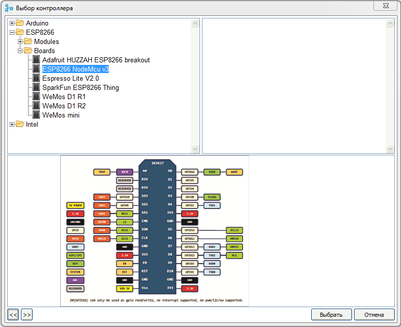
As with the Arduino, work on a project begins with the selection of a controller. Unlike previous versions, for the convenience of users, the controllers were transferred to a tree-like folder structure.
')
When choosing a particular controller or board, you can see its image, pinout, as well as technical characteristics.
The main work when creating a web interface settings is made in the project tree.
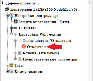
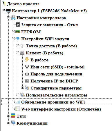
To begin, configure the access point.
We open the project tree to the point “ Access Point ” inclusively and double-click on the “ Disabled ” branch to enable the access point to work.
In the opened branches configure the settings of the access point. To change the required parameter, double-click on the corresponding branch.
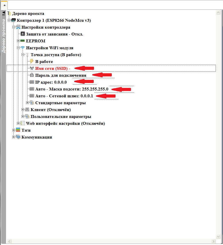
Network Name (SSID) - The name of the network that the access point will organize.
Connection password - password to connect to the access point. If left blank, the access point will be without a password with a free connection.
IP address - the IP address that the controller will have on the network created by the access point. At this address you can then connect to the controller.
The remaining parameters ( Subnet Mask and Network Gateway ) will be filled automatically after setting the IP address, but if necessary, they can be changed if non-standard values are required.
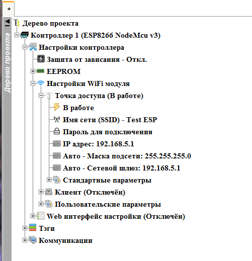
The result should be something like that.
With the access point finished, we can collapse this node, and proceed to the client. We also expand its node, and enable it to work by double clicking on the “ Disabled ” branch

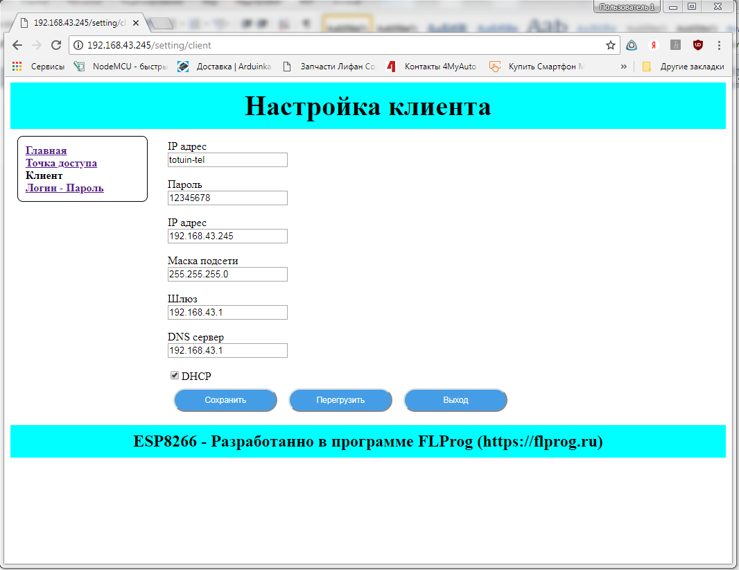
Customize the client. There are two options for customizing the client. Direct setting of network settings, and getting settings via DHCP. To begin, use the second option.
Please note that for security reasons the connection password is not shown in the project tree.
With the setting of Wi-Fi interfaces are finished. We turn off (if necessary) the client's site and proceed to setting up the firmware update mode via Wi-Fi (if required). This node appears only when the client is enabled.
Turn on this mode by double clicking on the branch “ Disabled ”
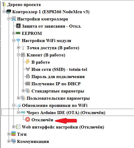
We set the necessary parameters (changing the value of the parameters is done with a double click on the corresponding branch).

Password - when setting a password, you will need to enter it before uploading a new firmware.
Device Name - This name will appear in the name of the connection port in the Arduino IDE.
Read more about the Arduino OTA mode here .
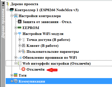
Now we proceed directly to creating a web-based configuration interface. Open the “ Web interface settings ” node and enable it by double clicking on the “ Disabled ” branch
Web settings interface is a set of pages with parameters. If there are more than one page, a menu is automatically generated to access them. For each page, you can set your own CSS styles, if you use common styles for the entire Web interface settings.
To customize common CSS styles for the entire web interface, double-click on the “ Common Style ” branch.
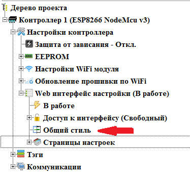
The general style settings window will open.
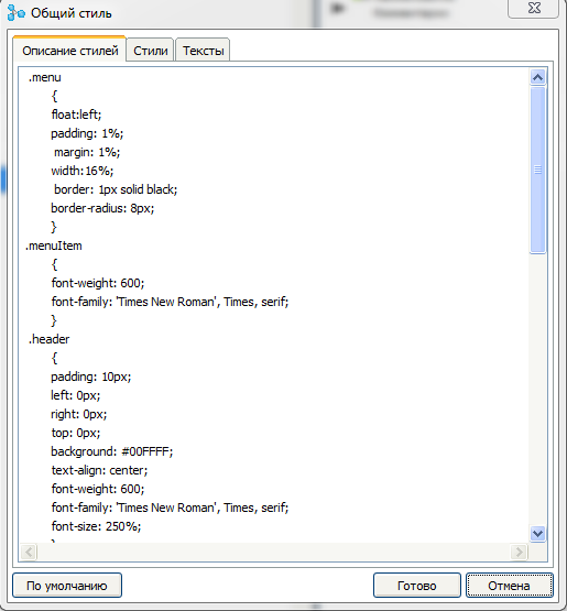
On the “ Description of Styles ” tab there is an input field for a description of the styles used for all customization pages. By default, this field is already filled with styles to create a standard interface. But if you want to change the design of the pages, you can change them.
On the tab " Styles " you can set the names of styles used for specific elements of the page.

This tab is also filled in by default.
On the " Texts " tab, you can enter the texts of the main elements used on the page.

To restore all values of this dialog to the default values, you can use the “ Default ” button.
The style and text settings specified in the common styles are applied on all settings pages, if they are not covered by the specific style settings for the page (this is discussed below)
Pages are shown in the Settings Pages node. We open it.
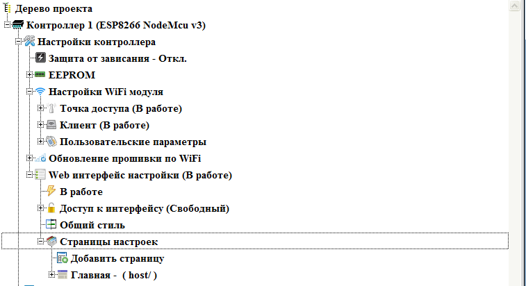
By default, there is always one page. Having opened its node, we get access to its settings.
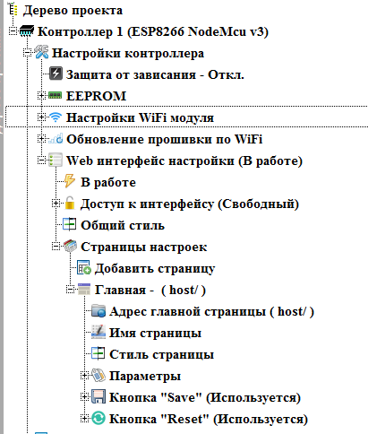
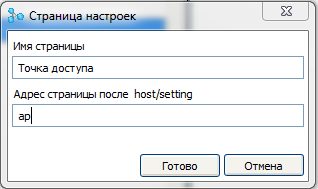
The address of the main page is the address of the main settings page. The default is host — that is, the controller's address on the network. If necessary, you can change. Change it to the address host / setting (double click on this thread).

Page name - the name of the page in the menu. Leave her name - " Home "
Page style - double clicking on this thread brings up the style settings dialog for this particular page.

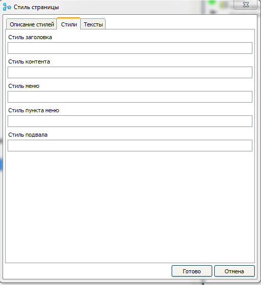

In this dialog, you can add additional CSS styles for this page and assign styles and texts for design elements. You can also override the styles described in the general styles dialog.
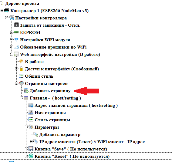
In the “ Parameters ” node, parameters are displayed that are displayed on the page. On the main page, we will set the display of the IP address obtained from the router via DHCP in plain text. Parameter is added by double-clicking on the " Add Parameter " branch.

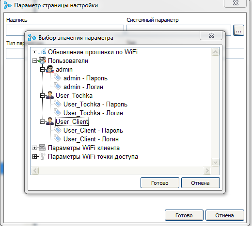
The dialog for creating a new parameter opens. In it, for a start, press the system parameter selection button.
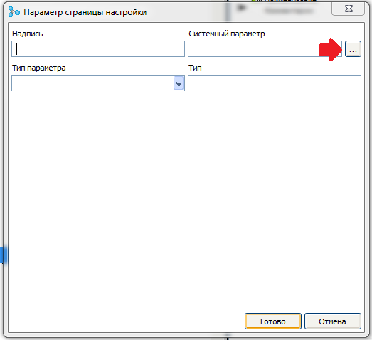
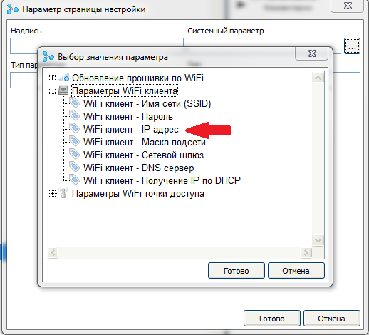
A list of available system parameters opens. Select the option “ Wi-Fi client - IP address ”.
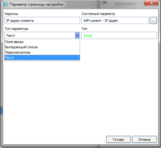
In the label field, enter the text labels for this parameter, and in the parameter type field, select the value “ Text ”
After creating a parameter, a new project tree node will appear, in which you can adjust the style for this parameter, change the parameter settings or delete it.

The “ Save” button and the “Reset ” button nodes specify the presence of buttons for saving data and reloading the controller on the page. Since we don’t have any changeable data on the main page, we’ll disable these buttons on the page by double clicking on the “ Used ” branch (by default, the buttons are on the page).

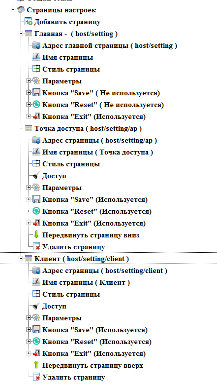
Add a new page by double clicking on the branch " Add page "
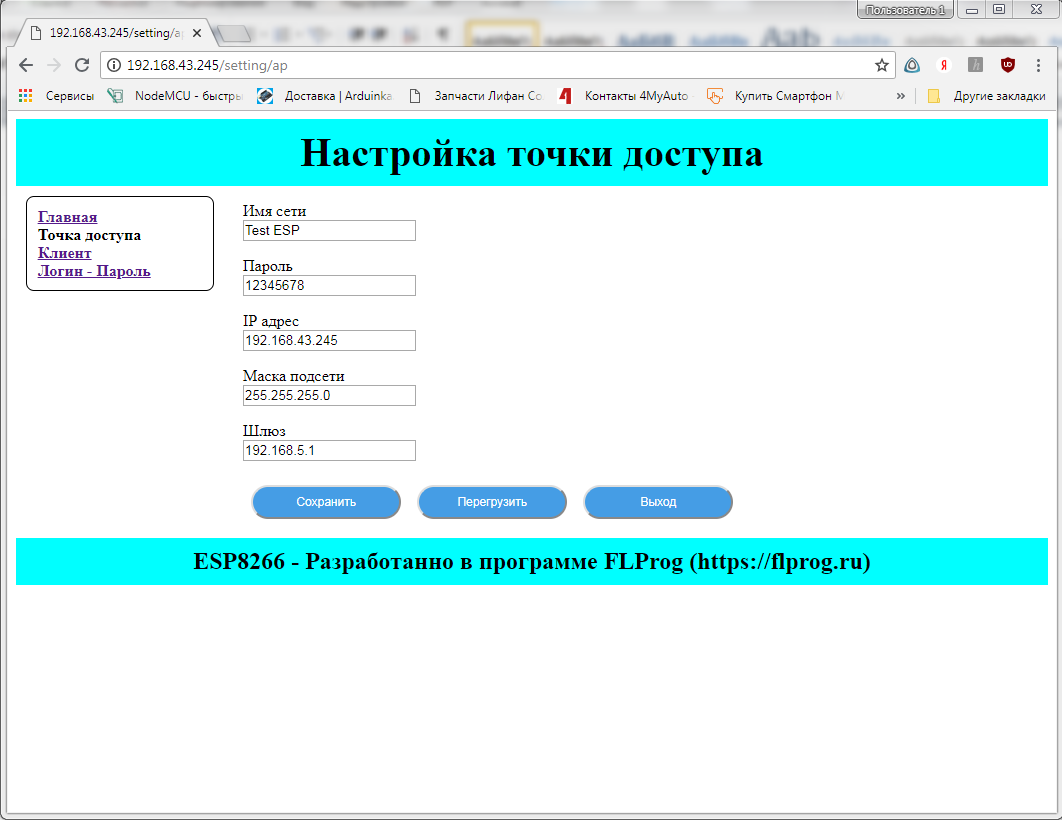
A new page dialog will open. In it we will fill in the name of the page (as it will be called in the menu of the setup interface) and the address. Addresses of the auxiliary pages always continue the address of the main page. On this page we will configure the parameters of the access point.
Just as for the main one, in the new page node you can change the page address, name, set styles for this particular page, set the displayed parameters and the presence of buttons. Well, in addition there is the possibility of deleting the page.

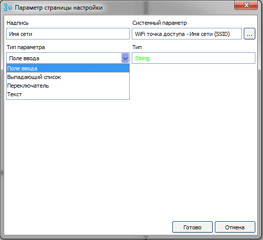
Add the “ Wi-Fi access point - network name (SSID) ” parameter to the page

And choose for it the type of " input field " and the label " Network Name "
In the same way we will add other parameters of the access point.
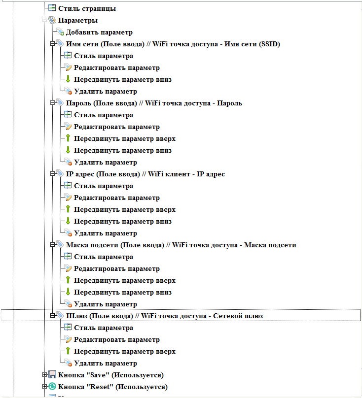
If there are more than one parameters on a page in the parameter nodes, branches appear that allow you to change the order in which the parameters appear on the page.
Since there are editable parameters on the page, we will leave the save and reload buttons on the controller.
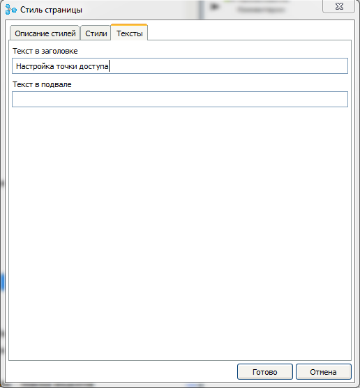
For this page in the style dialog, we will set a title for this page.
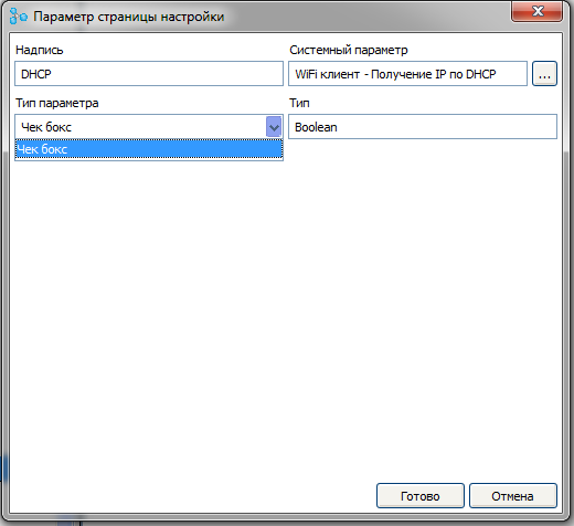
In the same scenario, create a page with client settings. For the parameter “ Wi-Fi client - receiving IP via DHCP ” we will set the type of the parameter “ Check box ”
If there are more than two pages in the interface, the branches that control the position of the pages in the interface menu also appear in the page nodes. But the main page is always the first.

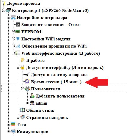
At the moment, access to the interface and all pages is free. Let's enter access restriction. To do this, double click on the “ Free Access ” branch of the “ Access to Interface ” node

Now you will need to log in to access the interface. The time of active authorization can be set. By default it is 15 minutes. After this time, after the last activity of the user, the current user will be automatically reset. This time can be changed by double clicking on the corresponding branch.
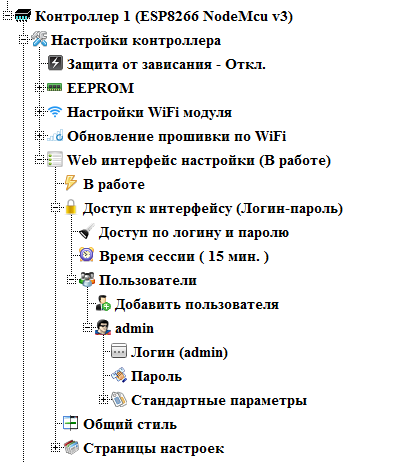
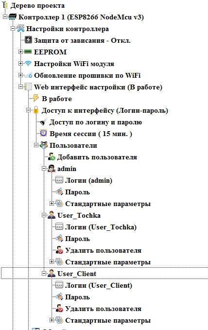
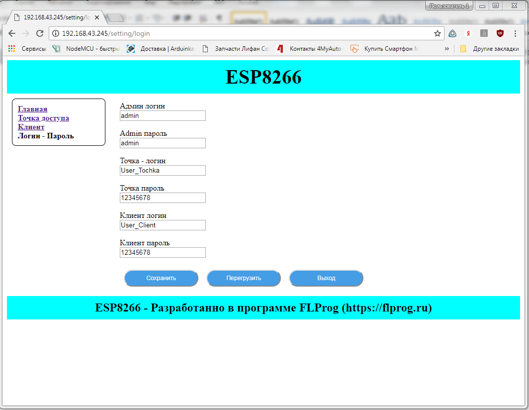
In the " Users " node you can set the required number of users. There is always a super user (by default, the username is admin ). All pages and options are always available to him. As with any user in his site, you can specify a username and password.
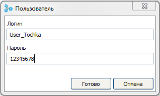
Create a new user who will have the right to configure the access point. To do this, double click on the " Add user " branch. The add user dialog opens. In it we will set the login and password of the new user.
And create another user who can customize the client.
After enabling access by login and password, the “ Exit ” button appeared on all pages, which serves to exit the current user. Leave it on all pages.
Now we will configure access on pages. Home page is always available to all users. And in the nodes of the remaining pages, a new “ Access ” branch appeared. Double click on this thread in the Access Point node.
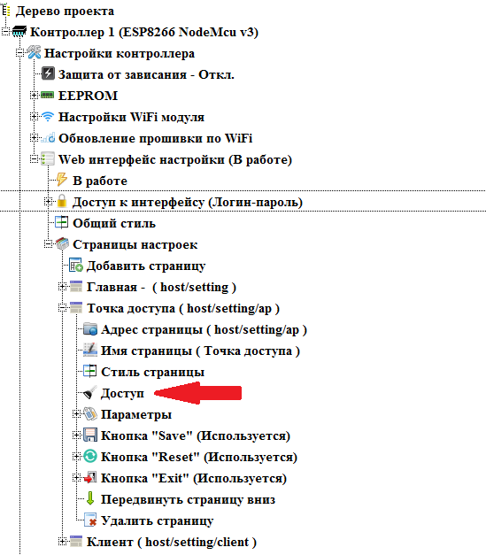
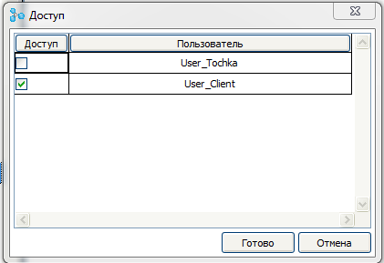
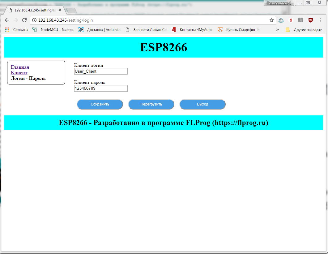
A dialog opens to select users to access the page. By default, access is open to all users. Uncheck User_Client , thereby limiting its access to this page.

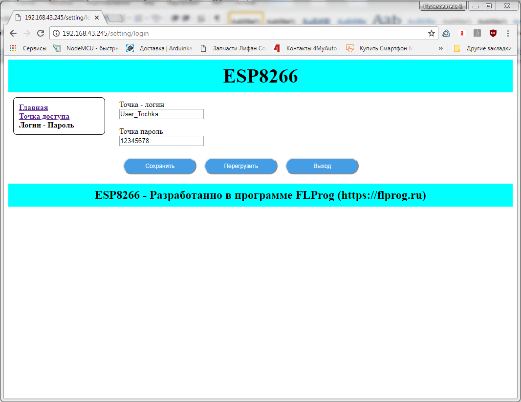
In the same way, we restrict access to the client settings page to the User_Tochka user .
Let's create another page for login and password settings.
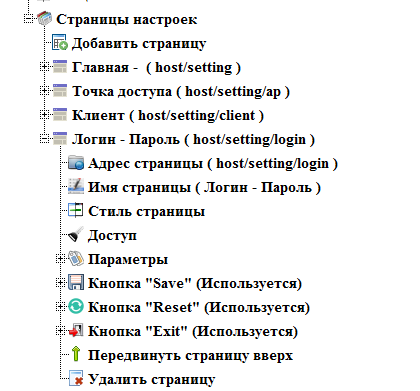
Add to this page the parameters of logins and passwords for all users. These parameters appeared in the list of system parameters after enabling access by login and password.
For this page we will not configure the access restriction, but configure the restriction directly on the parameters. Access settings appeared in the parameter nodes similar to the page access settings.
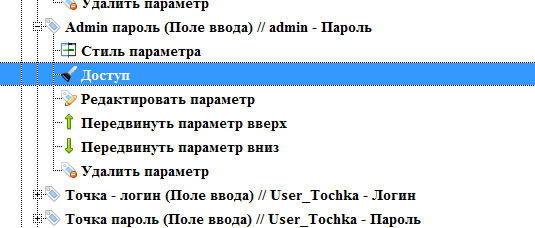
We will deny access to the admin settings for both users, and we will only allow access to the user settings for the user to whom these settings belong.
We consider the configuration of the web interface to be complete.
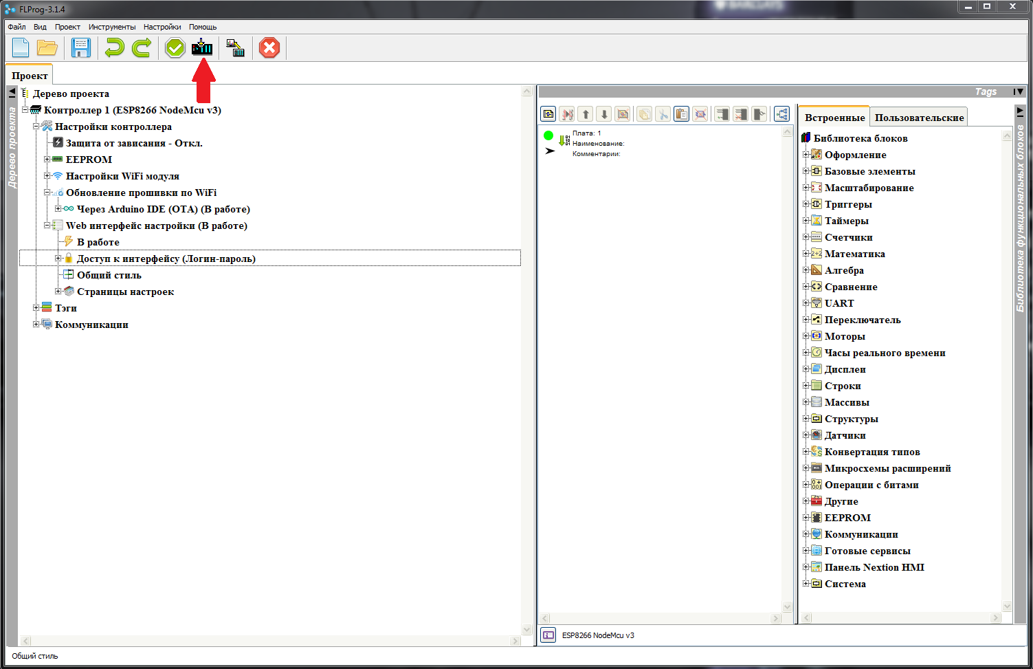
Click the button "Compile project" in the main interface of the program and get ready to sketch in the Arduino IDE.
In the Arduino IDE choose our board.
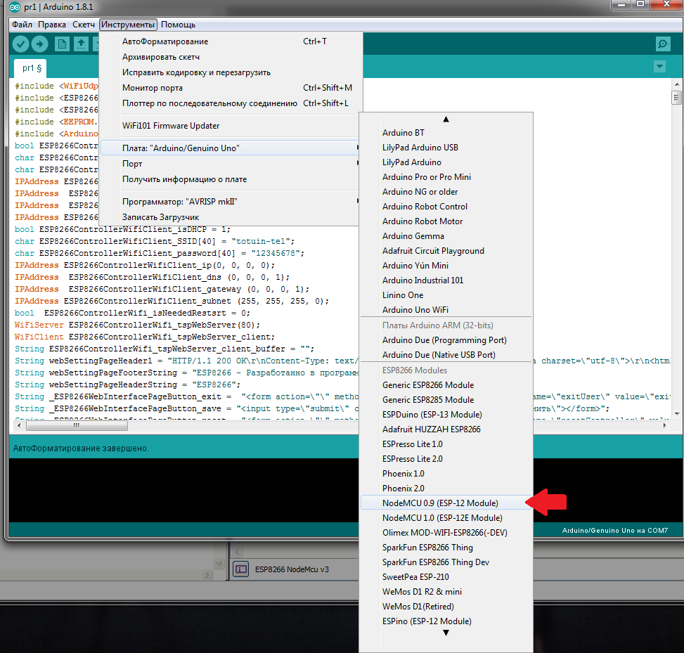
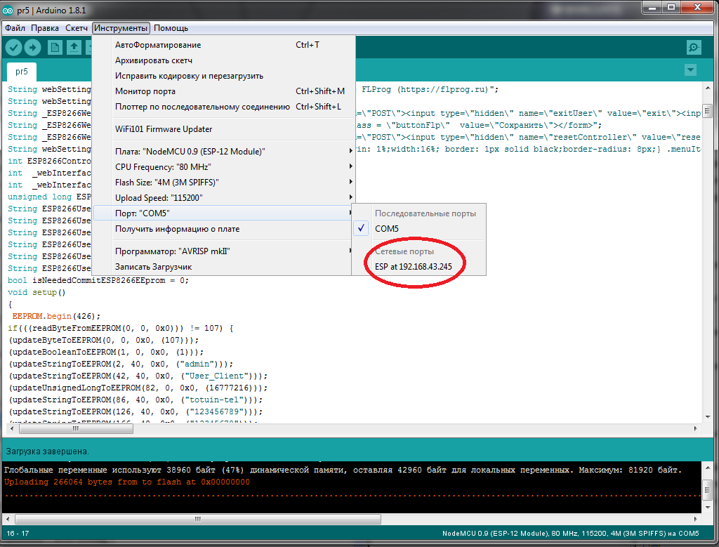
And the port to which the controller is connected

Then we upload the firmware to the controller

So, what we did ...
After downloading, a new access point appears.

Connect to it and go to the address given by us in the project. An authorization page appears.
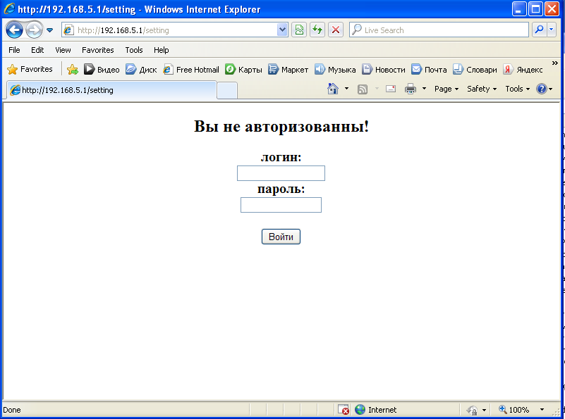
Enter the password and login administrator, and get to the main page

We see all pages in the menu
And on the login and password page all the parameters.
We exit and log in as User_Tochka . We see only accessible pages in the menu, and only our login and password.
We are logging under User_Client and the picture is appropriate - we see only what is necessary
We open the Arduino IDE and in the port settings we see that the controller is ready to update the firmware “by air”.
That's all for today.
In the next lesson, we will look at user-defined system parameters, and synchronization with time servers. Download the project created in this lesson here .
UPD.
This lesson is created for version 3.1.4, which is now in pre-release testing. Download it here . For more information about the project FLProg can be found in the company's blog on Habré , the project site and forum . In addition to the channel ArduinoProm you can watch a huge variety of video lessons.
Source: https://habr.com/ru/post/422053/
All Articles