How I did a line-interactive UPS (Part 2)
In the second part of our cycle, we will continue the conversation about measuring alternating voltage, as well as measuring the output load current. I ask all interested under cat.
Part 1
Part 2
Part 3
The measurement of actual value has already been repeatedly written in various sources. I personally liked the following the most:
Budget version of TrueRMS measurement
Method of measuring the effective value of voltage using MK
Briefly and clearly all the formulas are written
Calculation of average and rms current / voltage values
')
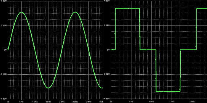
In short, the essence of all such complex calculations is that the voltage in the mains itself can be different from a perfectly sinusoidal form, moreover, in the case of a UPS with a modified sinusoidal output, when working from the inverter, the output signal will also be remote remind sine. Therefore, if you simplify the measurement and consider the mean straight value, the results will be very different from the real ones.
Here is an example of what happens at the UPS input and at the output (taken from here ):
In my case, the algorithm for calculating the effective voltage does not possess any uniqueness. With a frequency of 1121 Hz (for digitizing the voltage with a frequency of both 50 and 60 Hz), a timer interrupt is triggered, the ADC is started and measurements are made on three channels (input voltage, output voltage, output current). After accumulating 90 measurements, they are calculated and effective values are calculated.
The sum of the squares of the quantities is calculated directly in the interrupt, and in the main program loop, already using floating point arithmetic, the averaged effective values are calculated (over 20 points).
All operations are performed on an 8-bit PIC18F26K22 microcontroller. Someone can immediately ask the question: why not STM32, they say it is more powerful, cheaper, etc. I will answer immediately. The STM32 controller is good, but it somehow didn’t survive, although it was used in some projects.
Most of our tasks do not require vast computational resources, so there are more than enough 8-beatniks here. In addition, for the PIC18 there is a huge number of developments and own service software, and this is very important, because significantly accelerates new developments, allowing you not to be distracted by the study of an unknown periphery. And it always takes the most time.
Also, the PIC18 has a lot of advantages. These include the built-in calibrated generator, the minimum external piping, the supply voltage range from 2.5 to 5V, good integrated peripherals, powerful outputs with currents up to 25 mA, etc. Works MK at a frequency of 64 MHz.
Measurement of the current consumed by the load is carried out by the ACS712ELCTR-30A-T integrated sensor (at 30A) of the Allegro company. The sensor generates an analog signal proportional to the current flowing, taking into account the sign. If the current is positive, the signal will be more than 2 V, if negative, then less than 2 V. The signal given by the sensor is digitized by the MC and is used to control the load. Now the manufacturer indicates on the website and in those. documentation that these sensors are undesirable to use in new developments, and instead of them advises a more modern model from the ACS723 series. But so far, it is much easier to buy ACS712 models in Russia from suppliers, and even cheaper.
The sensor is extremely convenient in that it allows a direct connection to the ADC MK, it requires only one 5V power source, and also provides a galvanic isolation (in fact, the sensor is contactless, operating on the Hall effect). The last point is important because It is highly desirable to conduct current measurement in a phase conductor so that the entire neutral of the UPS is so-called “through”, i.e. essentially representing one single conductor. This same sensor can be easily used in breaking any conductor, which simplifies the whole measurement scheme.
However, one interesting moment is connected with this sensor. According to the documentation, it can withstand one current pulse in 100A with a duration of 100 ms. Further, irreversible destruction of the chip may occur. Naturally, a circuit breaker is installed in the UPS in the input circuit. But the time of its operation is just commensurate with the duration of the pulse. Here is an example of the time-current characteristics of a type C machine:

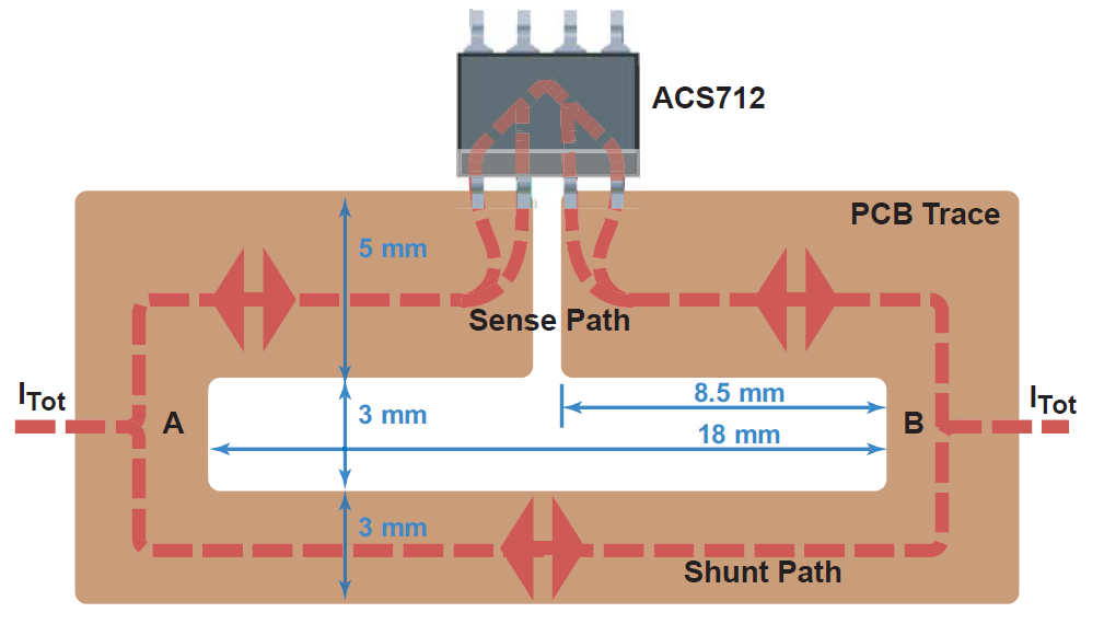
In order to have some margin of safety in the event of a short circuit on the printed circuit board of the UPS, an additional shunt was manufactured according to the recommendations of the manufacturer of the sensor itself ( link ).
The point here is quite simple. The resistance of the internal shunt of the ACS712 sensor is 1.2 mΩ. It is proposed to make the second such shunt on the printed circuit board in the form of a conductor of the desired shape, thus increasing the current limit by half (up to 200A), which will allow the circuit breaker to operate much faster.
The dimensions of such a current shunt on the PCB are shown below:
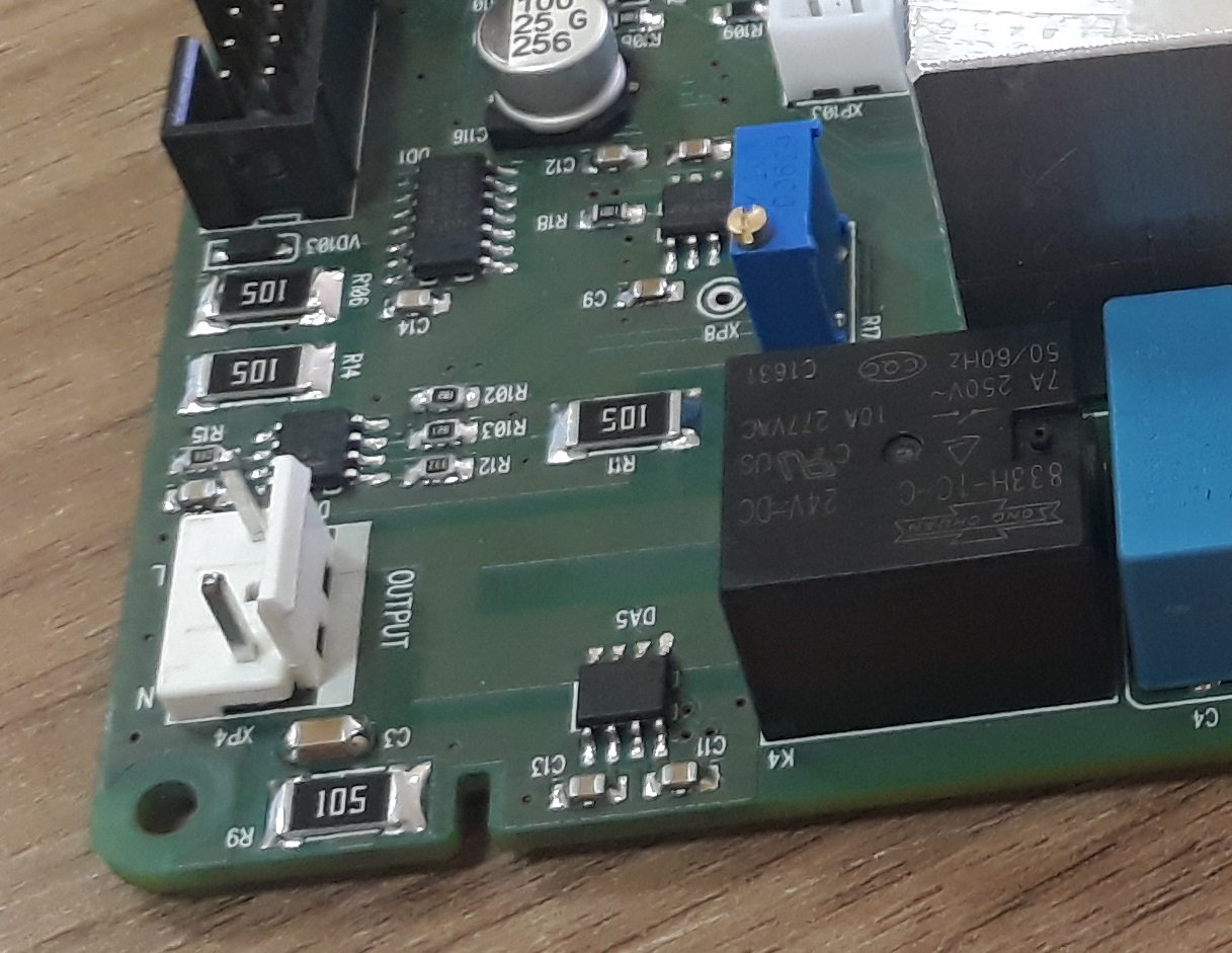
This is how it looks live:
I want to note that this sensor is intended only to measure the current consumption of the load, in order to estimate the load on the UPS and automatically turn it off when the specified limit is exceeded. For example, a 600 watt UPS can output a maximum of 3A. If the load starts to consume 4A or more for some time (for example, about 2 seconds), then we simply de-energize it. The circuit breaker protects against a hard short circuit in the network mode. But in the mode of operation of the inverter, the protection is organized electronically, but using other sensors. This will be discussed a little later when considering the work of the inverter.
Part 1
Part 2
Part 3
Measurement of effective value of ac voltage or current
The measurement of actual value has already been repeatedly written in various sources. I personally liked the following the most:
Budget version of TrueRMS measurement
Method of measuring the effective value of voltage using MK
Briefly and clearly all the formulas are written
Calculation of average and rms current / voltage values
')
In short, the essence of all such complex calculations is that the voltage in the mains itself can be different from a perfectly sinusoidal form, moreover, in the case of a UPS with a modified sinusoidal output, when working from the inverter, the output signal will also be remote remind sine. Therefore, if you simplify the measurement and consider the mean straight value, the results will be very different from the real ones.
Here is an example of what happens at the UPS input and at the output (taken from here ):
In my case, the algorithm for calculating the effective voltage does not possess any uniqueness. With a frequency of 1121 Hz (for digitizing the voltage with a frequency of both 50 and 60 Hz), a timer interrupt is triggered, the ADC is started and measurements are made on three channels (input voltage, output voltage, output current). After accumulating 90 measurements, they are calculated and effective values are calculated.
The sum of the squares of the quantities is calculated directly in the interrupt, and in the main program loop, already using floating point arithmetic, the averaged effective values are calculated (over 20 points).
All operations are performed on an 8-bit PIC18F26K22 microcontroller. Someone can immediately ask the question: why not STM32, they say it is more powerful, cheaper, etc. I will answer immediately. The STM32 controller is good, but it somehow didn’t survive, although it was used in some projects.
Most of our tasks do not require vast computational resources, so there are more than enough 8-beatniks here. In addition, for the PIC18 there is a huge number of developments and own service software, and this is very important, because significantly accelerates new developments, allowing you not to be distracted by the study of an unknown periphery. And it always takes the most time.
Also, the PIC18 has a lot of advantages. These include the built-in calibrated generator, the minimum external piping, the supply voltage range from 2.5 to 5V, good integrated peripherals, powerful outputs with currents up to 25 mA, etc. Works MK at a frequency of 64 MHz.
Output current measurement
Measurement of the current consumed by the load is carried out by the ACS712ELCTR-30A-T integrated sensor (at 30A) of the Allegro company. The sensor generates an analog signal proportional to the current flowing, taking into account the sign. If the current is positive, the signal will be more than 2 V, if negative, then less than 2 V. The signal given by the sensor is digitized by the MC and is used to control the load. Now the manufacturer indicates on the website and in those. documentation that these sensors are undesirable to use in new developments, and instead of them advises a more modern model from the ACS723 series. But so far, it is much easier to buy ACS712 models in Russia from suppliers, and even cheaper.
The sensor is extremely convenient in that it allows a direct connection to the ADC MK, it requires only one 5V power source, and also provides a galvanic isolation (in fact, the sensor is contactless, operating on the Hall effect). The last point is important because It is highly desirable to conduct current measurement in a phase conductor so that the entire neutral of the UPS is so-called “through”, i.e. essentially representing one single conductor. This same sensor can be easily used in breaking any conductor, which simplifies the whole measurement scheme.
However, one interesting moment is connected with this sensor. According to the documentation, it can withstand one current pulse in 100A with a duration of 100 ms. Further, irreversible destruction of the chip may occur. Naturally, a circuit breaker is installed in the UPS in the input circuit. But the time of its operation is just commensurate with the duration of the pulse. Here is an example of the time-current characteristics of a type C machine:
In order to have some margin of safety in the event of a short circuit on the printed circuit board of the UPS, an additional shunt was manufactured according to the recommendations of the manufacturer of the sensor itself ( link ).
The point here is quite simple. The resistance of the internal shunt of the ACS712 sensor is 1.2 mΩ. It is proposed to make the second such shunt on the printed circuit board in the form of a conductor of the desired shape, thus increasing the current limit by half (up to 200A), which will allow the circuit breaker to operate much faster.
The dimensions of such a current shunt on the PCB are shown below:
This is how it looks live:
I want to note that this sensor is intended only to measure the current consumption of the load, in order to estimate the load on the UPS and automatically turn it off when the specified limit is exceeded. For example, a 600 watt UPS can output a maximum of 3A. If the load starts to consume 4A or more for some time (for example, about 2 seconds), then we simply de-energize it. The circuit breaker protects against a hard short circuit in the network mode. But in the mode of operation of the inverter, the protection is organized electronically, but using other sensors. This will be discussed a little later when considering the work of the inverter.
Source: https://habr.com/ru/post/422023/
All Articles