FreeCAD - a new drawing method
Disclamer : I have never in my life worked with CAD / CAM applications before, and, suddenly, I had to. The principles of the work of FreeCAD so delighted me that it requires an urgent post on Habr to tell others.
Written in this post is likely to be trivial and boring for most active CAD users, and this post is primarily aimed at non-CAD users in order to tell them about the wonderful new world of computer graphics.
Introduction
I had a simple task - to make a 3D model of my apartment. Not just "walls in size", but all beams, ledges and bends. I tried one, second, third program ... I was desperate (started with SweetHome3D, and ended with blender and inkscape). They were all damn uncomfortable. Among the programs that I tried, there was FreeCAD, which I missed due to "don't do anything" and "it doesn't work properly." After I despaired, I went through the second round. This time, a little more reading the documentation ... And FreeCAD not only took off, but also opened for me a delightful new world of accurate vector drawing based on the Constrains.
Modeling problems
To begin, I will talk about the pain that I suffered in different editors.
Let's start with SweetHome3D. The conditionally clear interface that allows you to describe the room as a "floor" (where the shape and protrusions are specified) around which the "wall" is made. SweetHome3D gave me two problems: pixel-hunting (the size changes either with microscopic mouse shifts or in dialogue, but there is no method to press the wall to the floor with accuracy - only pixel-hunting. The second problem - the SweetHome3D model does not imply the existence of beams, arches and other wall elements , not reaching from the top to the bottom. Additionally, SH3D does not know how to incline walls and floors (I would like this problem not to exist, but before resolving this problem IRL, it should be documented). Ie SH3D covers 90% of what I needed delivered I have incredible pain to 5%, and making it impossible for the remaining 5%.
Blender theoretically allows you to do everything, but only theoretically. In practice, either my skills were not enough, or the process itself is very slow, but having drawn three and a half corners, I gave up. Too slow and too much fussing with lighting and other unimportant things. Plus (as far as I know), Blender can hardly show normal 2D projections with dimensions.
Inkscape was good except for one problem - in the multisection line (F2) it is impossible to set the dimensions of each section. It would be possible - I would have painted everything in Inkscape.
... But my post is not about the absolute superiority of FreeCAD over Blender (I can’t really compare them to both of them), but about a new drawing style. First, about the problems of the old style (that is, the "usual" vector pattern).
The problem of pixel-hunting
Before moving on to the pictures and explaining the Constrains idea, I want to focus on a few problems that vector graphics have eternally pursued:
Almost united curves. If the two curves are almost touching, then you might think that they are touching. At some point (when printing, or with further manipulations), the picture will fall apart.
Almost parallel / perpendicular lines. They are parallel, but not completely.

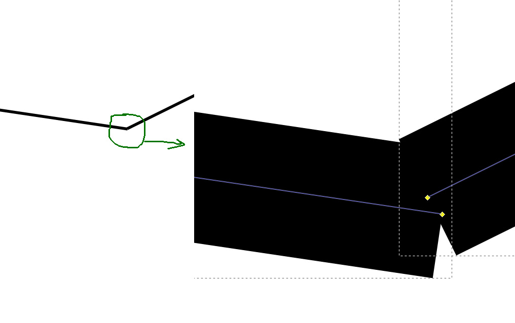
notice the outline, it shows that the descriptive rectangle for two lines is larger than the line itself, i.e. line at an acute angle.
the derivative of the previous one is the lines joining at an angle of 0.001 °.
inaccuracies in size and thickness of lines. The line has its thickness, and when editing (turning, resizing, etc.) the thickness begins to float. Moreover, in most vector reactors it is difficult to draw a square with an area of 100 and a line thickness of 0.5 (because the line goes 50% to the area of the figure, and we have not 10x10 inside, but 9.75x9.75).
Maintaining alignment and symmetry is a task that requires constant attention.
The editors have many tools built in to deal with such troubles, but these tools have one difficulty - they need to be meaningfully applied where the problem has arisen. And for the occurrence of problems you need to watch yourself.
Contrains
It was a long introduction. Now I am talking about constrains, or, in Russian, holding connections (translation of the term from the article about the degree of freedom in mechanics .
Let's try to draw a square with side 10, based on its fundamental properties.
The square has 4 straight sides.
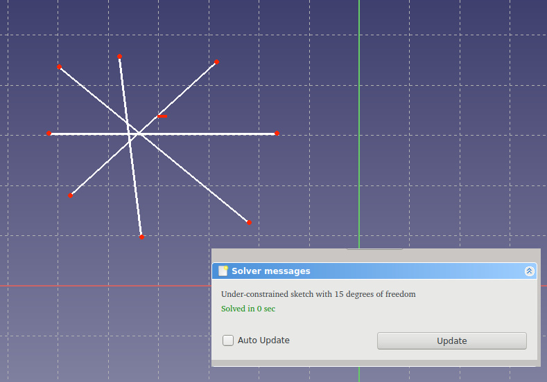
Almost got it. Solver suggests that we need to set 15 additional holding links so that our figure is unequivocal (she had 0 degrees of freedom).
- The opposite sides of the square are parallel *
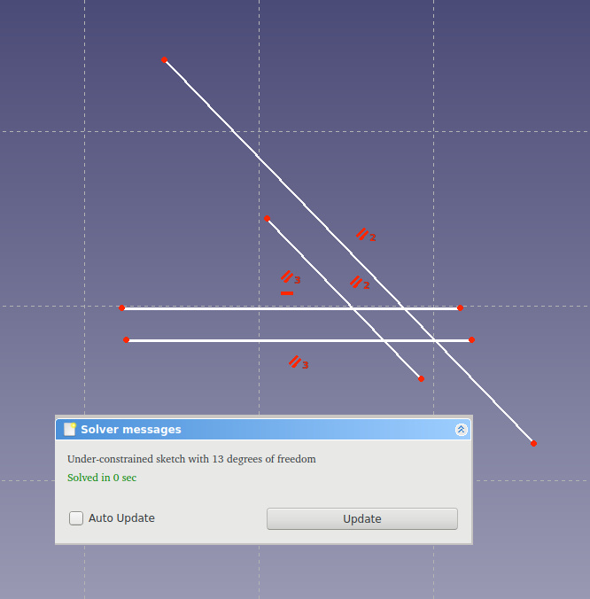
Solver says it's better. It became missed 13. Note the red marks - this is an indication of constrains. At the very beginning, we accidentally got two restrictions - two horizontal lines.
It became better, although it still looks like a square. What is wrong? Oh yes, a square is a polygon, and at the polygon the sides converge to a point in the corners. Add these restrictions.
It turned out a little unexpected, although the solver is more and more pleased. This figure is the usual quadrilateral in which the sides are pairwise parallel. A little outside the school course, but quite understandable.
Add volume ... a plane to this figure. Neighboring edges are perpendicular.
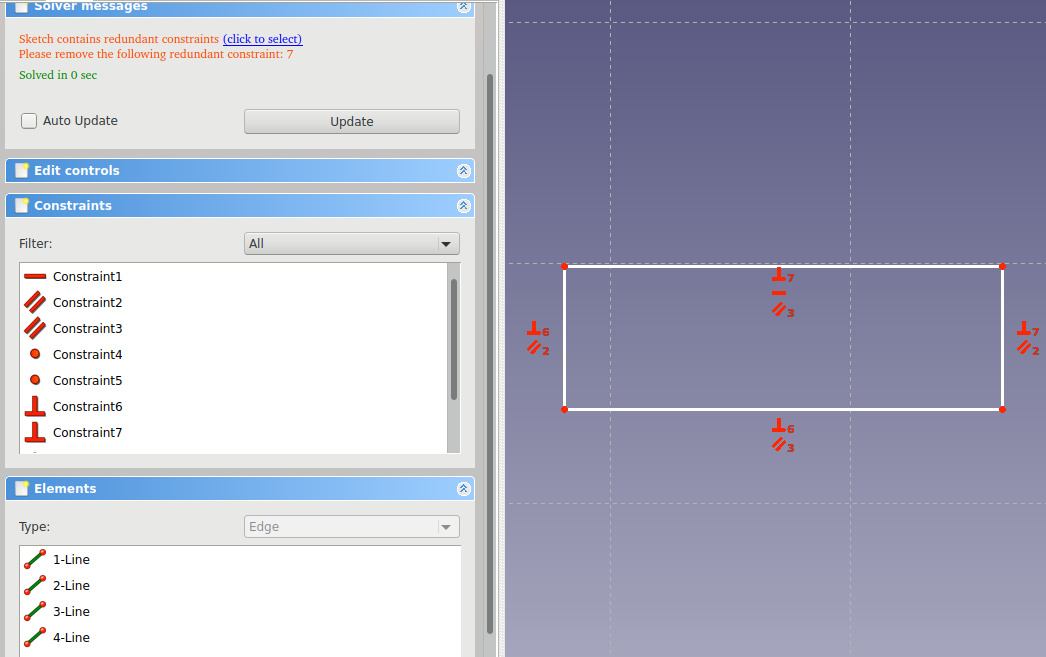
Already it seems to be true (although I pulled the picture up a little bit, because the sides of zero size completely suit the solver as perpendicular to the straight line on which they lie (in the form of a point)). solver swears at an excess of restrictions. We agree with him and remove one perpendicularity (we have the requirement of pairwise parallelism, perpendicularity for one pair automatically follows from the perpendicularity of the first pair). After we have deleted too much, solver complains about 4 freedoms.
We will forbid something else, because there is too much freedom.
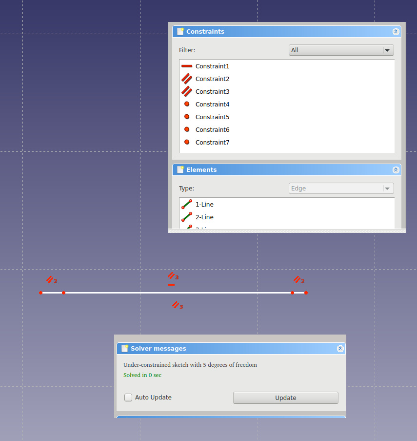
For example, let's say that all parties must be the same size. It is enough to do this for any two adjacent sides, and from this it follows that all sides are equal (school geometry!).
After that, we get three freedoms. Three more freedoms? But the square is ... Yes, it is a square, but we do not know its size (0 is also the size, by the way), and its position in space.
Let's set it - we will specify that one of the corners of the square lies on the point "0, 0", plus we will set a size of 10 mm for one of the sides.
Everything, the square is completely ready, it has no freedoms, and therefore there are no hidden errors.

This example was a little grotesque, but, I hope, expressive. I was particularly impressed that the solver not only checks for ambiguities, but also warns if the shape contains more restrictions than necessary.
Lyrics
For me, this method of describing the picture is completely new and unexpected. In a sense, it resembles what typed programming languages do with machine code — they add constraints to it, which allow to set constraints on possible operations with data in a mathematically precise form. At that moment, when there are a lot of restrictions, we get an unambiguous solution, which is exactly and unambiguous. And exactly correct if the input was correct. And no "accidentally touched the mouse" or "hand trembled."
')
Source: https://habr.com/ru/post/422019/
All Articles