Raspberry Pi cartridge from NES
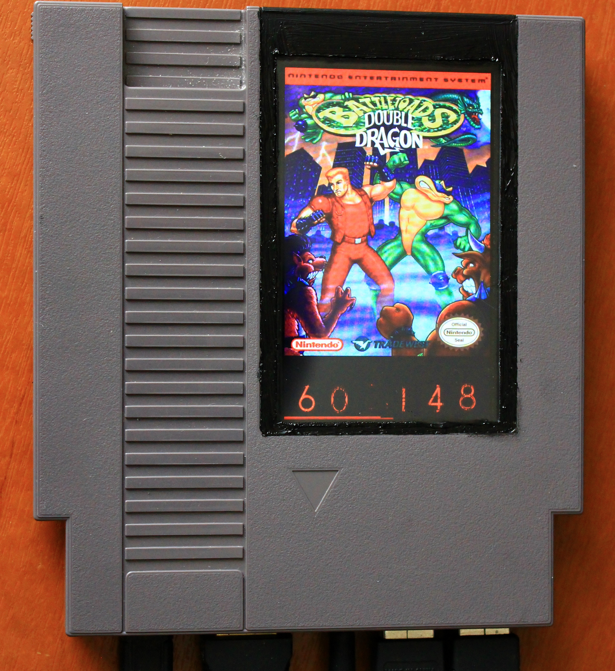
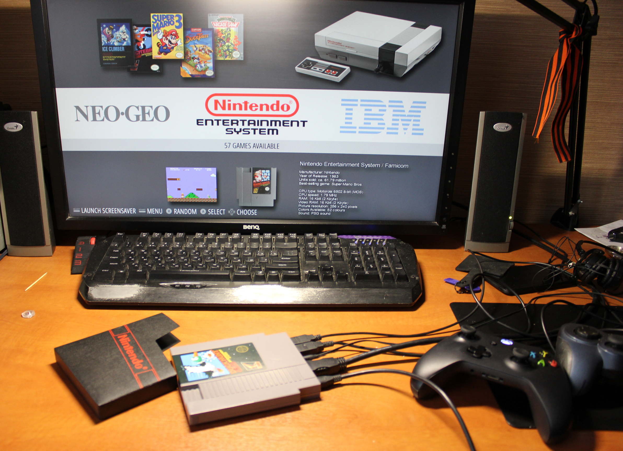
Hello! This is a retro gaming console based on the Raspberry Pi. In the cartridge from the game console NES. An integrated screen can be used for the game. When outputting the same video via HDMI, it shows the image of the game cover, as well as the core temperature, see the photo. I suggest a little ponastalgic and read about the assembly and configuration of such a device. Carefully, further a lot of traffic and photos.
Nostalgia
In childhood, we, who are now 25-35, loved to play consoles. Then there was no newfangled word of the console, so I will call them that. My acquaintance with consoles began with Dandy (clone NES). Super Mario Bros, Contra, Ducktales, Battletoads are just some of the hits of that time. Then the whole court was going to play with my friend in Sega (Sega Mega Drive), in such hits as Sonic, Ultimate Mortal Combat 3, Contra Hard Corps and more . And when the Play Station came out, I must say, she didn’t get to us right away, the Resident Evil series caused some truly scary delight.
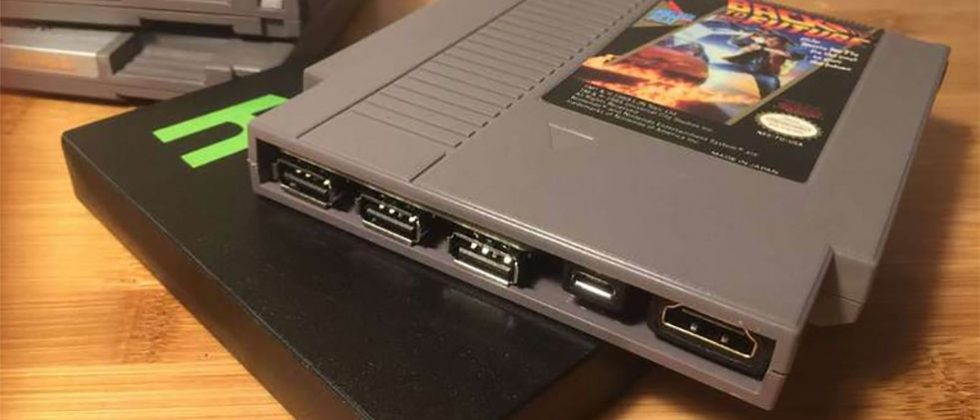
This picture helped me to wipe away a tear of nostalgia. I must say, I'm not the first who came up with the Raspberry Pi inserted into the case of the NES cartridge. Yes, this is not my device. And this cartridge is suitable for these purposes almost perfectly, it is small and beautiful. And inside a lot of space. Judge for yourself.
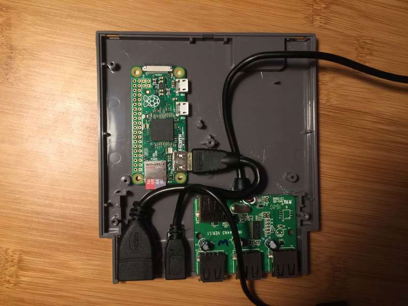
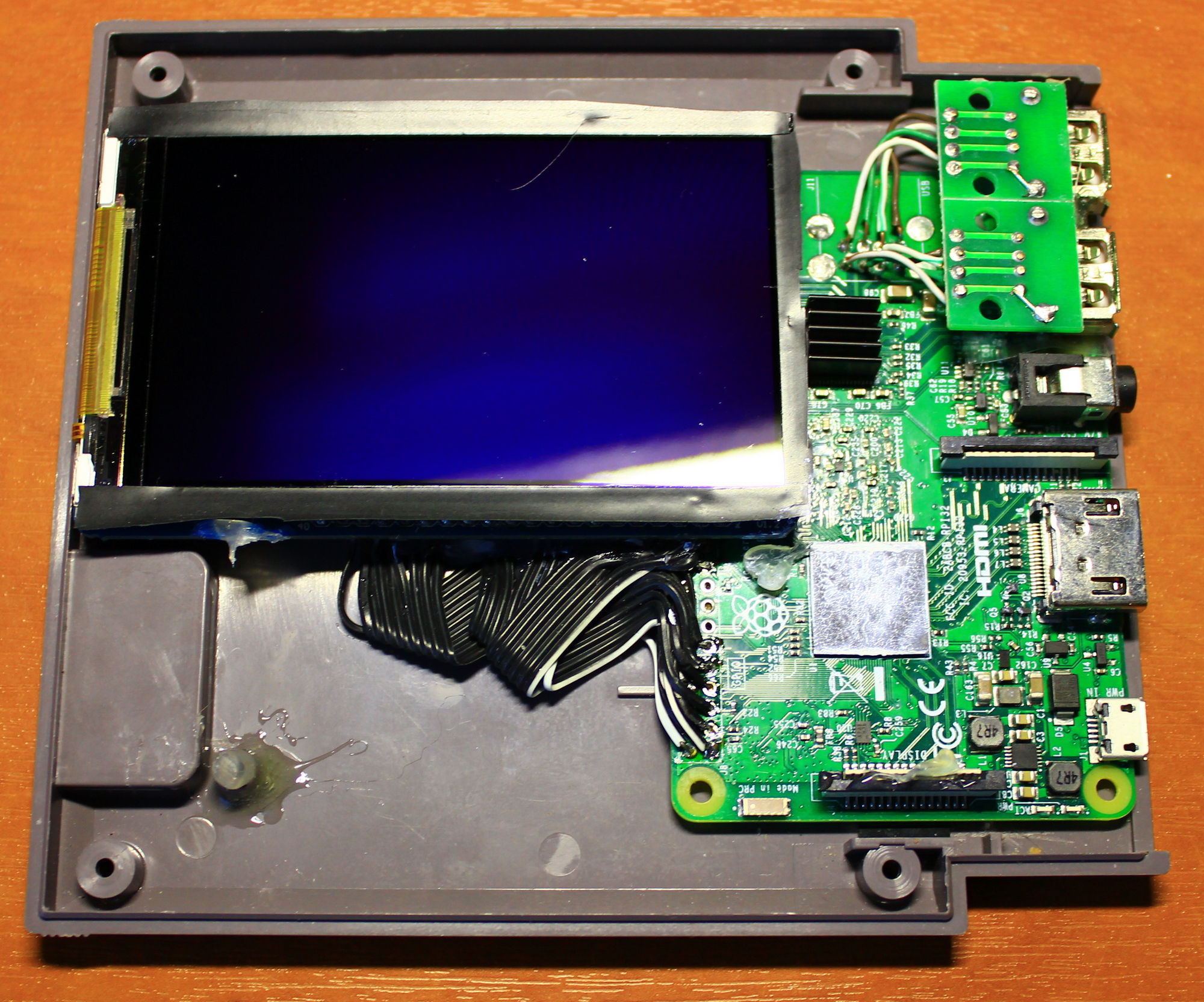
Inside a Raspberry Pi Zero, a USB hub, and a pair of extension cords. All sticks are planted on hot-melt glue.
')
Assembly
I wanted to collect something the same or similar. The same cartridge was selected from NES. Other options are either very small or they don't look very good. As the fiery heart of a retro car made Raspberry Pi 3B. Were purchased on Ali, also, USB connectors with convenient leads for soldering. Here it is.
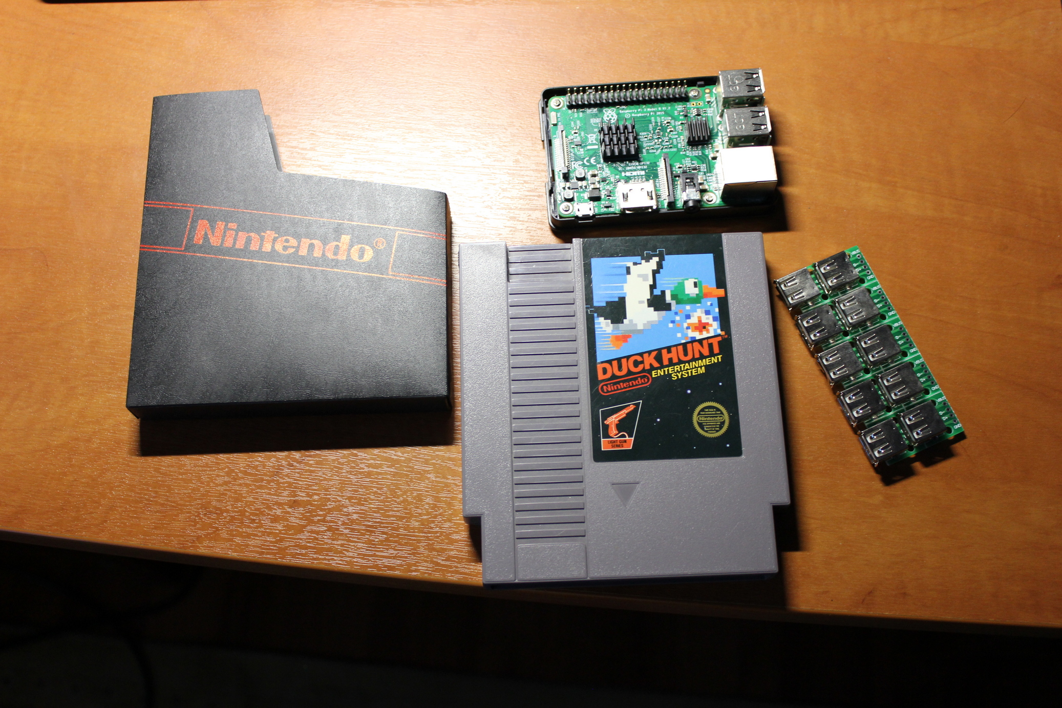
Oh yeah, you will repeat this project, do not take hit cartridges. There are so few of them left. Take something more common or less known. There is also an option to take a cartridge with Ali, but the original, it warms the soul. My 1986 release.
You will also need a special nes screwdriver screwdriver if the cartridge is screwed into three screws. There are also early versions of cartridges with five screws; they are unscrewed with a conventional flat-head screwdriver. I have just this.
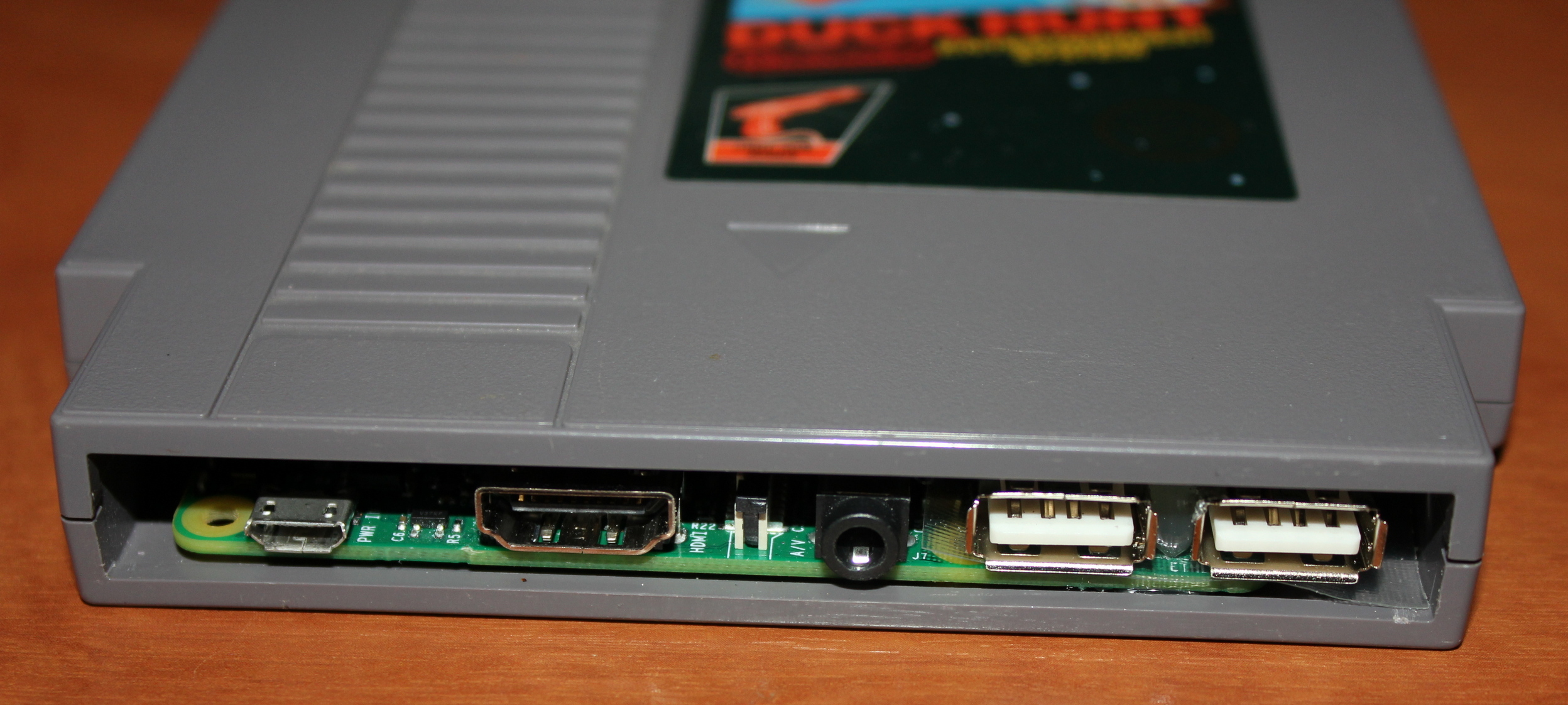
From the cartridge with a stationery knife and a sheet from a hacksaw, all interfering parts are cut and sawed.
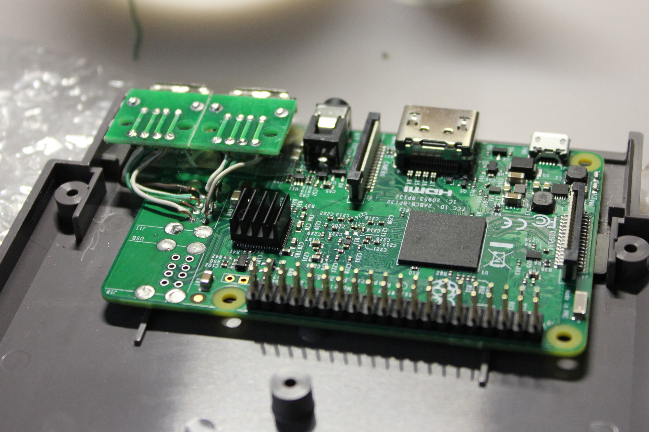
With the Raspberry Pi, protruding connectors were soldered. Experts say that you can do without a soldering station, if you first carefully disassemble the connectors with pliers, and then drop out one foot. All glued to the glue. Between connectors USB and raspberry laid insulator of non-melting plastic. Do not forget to connect the GND Raspberry Pi and the USB connector case (not shown in the picture above). Otherwise some joysticks will not work.
The last Retropie was installed on the raspberry . At first, Recalbox was standing , but I refused it, because it does not support the vibration of the joysticks on the Playstation 1 consoles. But I must say, the Recalbox is slightly more convenient in terms of what works out of the box and do not need to tune anything. In Retropie a lot of settings, you can customize infinitely. By this I liked him.
That's what happened. Connect any joysticks with xinput.
Screen
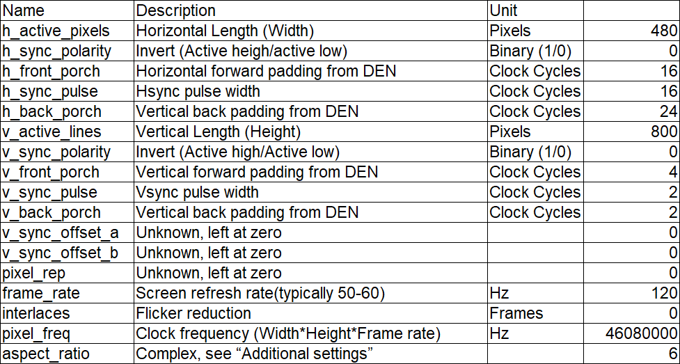
Appetite comes with eating. How about embed screen in a cartridge? To play or display the image of the game cover. Such a screen has been ordered. This is an 800 * 480 3.5 inch screen with a parallel DPI interface that uses almost all GPIO Raspberry Pi. It works for me in 120 Hz mode (but the render is still 60 Hz), the response is instant. The only negative is the 6-bit matrix. Only 262,144 colors. Although, in general, it is not particularly noticeable, judge for yourself.
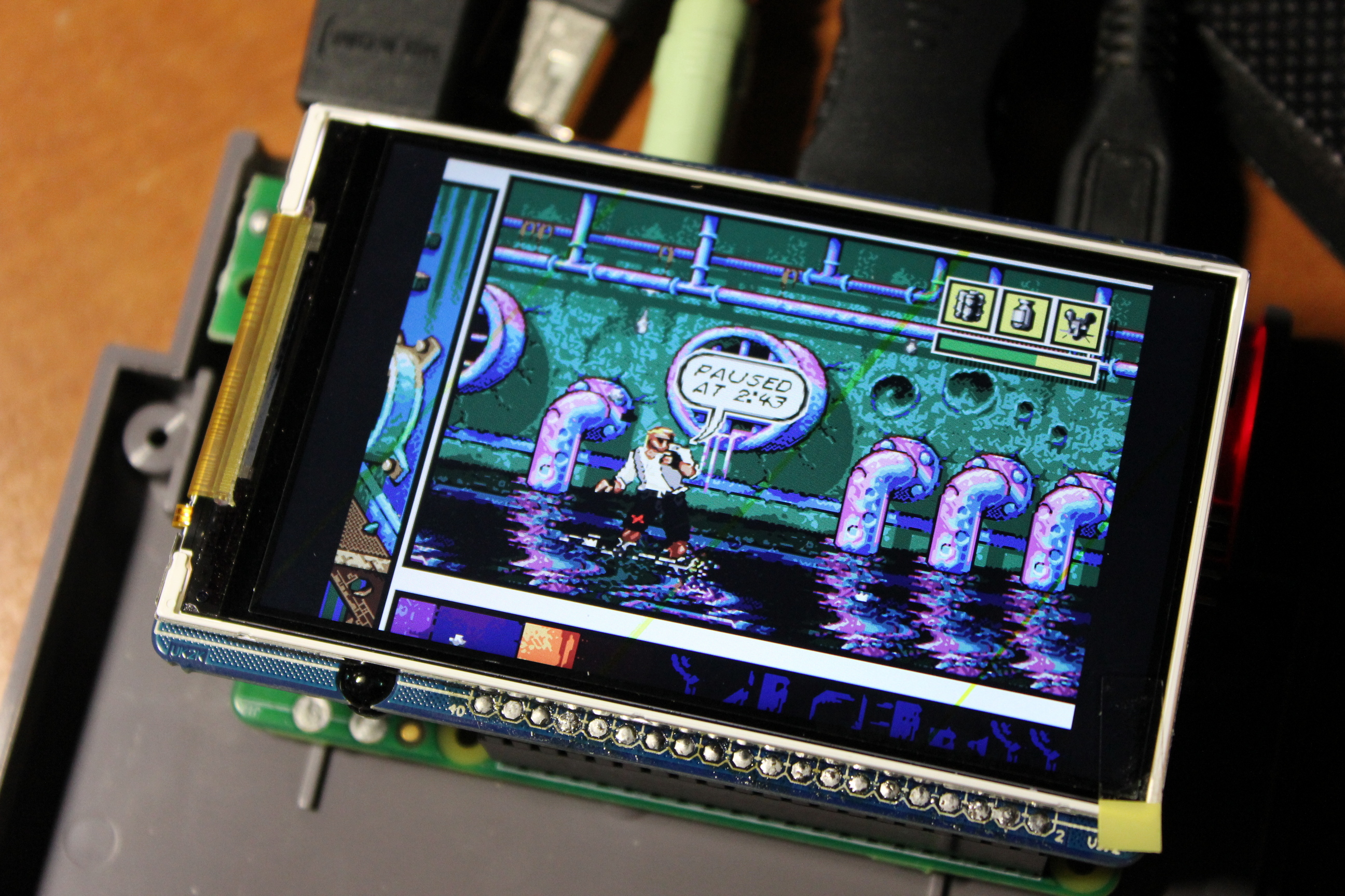
All the legs from the screen and the Raspberry Pi were soldered. The screen was soldered with two cables from an old IDE cable. Under the screen installed mortgages in 5mm, it does not touch the bottom wall of the cartridge. Electrical tape is glued around the perimeter of the display so that there are no side lights. All glued to the glue. On the top cover, I cut through the window and pasted glass 2mm thick.
In order to run the image output on this screen, you need to fix the config / boot / config.txt . I recommend WinSCP program for Windows owners, which, when connecting to Raspberry Pi via SSH, gives the presentation of files as in Total commander'e. Very comfortably. Especially if you run it in shell mode sudo su - , which gives access to all files.
Unfortunately, when the DPI screen is on, video output via HDMI does not work. Therefore, I created two config files in the / boot / folder, one config_hdmi.txt , the second config_dpi.txt . In the config_hdmi.txt config, the resolution is 1080p60Hz and overscan is removed. config_dpi.txt contains the DPI screen settings.
config_dpi.txt
# uncomment if you get no picture on HDMI for a default "safe" mode #hdmi_safe=1 disable_overscan=1 # uncomment to force a specific HDMI mode (this will force VGA) #hdmi_group=1 #hdmi_mode=1 # Sound output. Set to 0 or comment for autodetect, 1 for DVI, 2 to force HDMI. #hdmi_drive=2 # Using /etc/modules is deprecated and no longer supported on 4.4 kernel # So manually enable audio dtparam=audio=on config_hdmi_boost=0 # force hdmi while the tv can take time before sending the signal on the hdmi output hdmi_force_hotplug=1 # uncomment for composite PAL #sdtv_mode=2 # uncomment for lirc-rpi #dtoverlay=lirc-rpi #3.5 HD tft screen 800x480 dtoverlay=dpi24 overscan_left=0 overscan_right=0 overscan_top=0 overscan_bottom=0 #Banggood framebuffer_width=800 framebuffer_height=480 dtparam=spi=off dtparam=i2c_arm=off enable_dpi_lcd=1 display_default_lcd=1 dpi_output_format=0x6f015 dpi_group=2 dpi_mode=87 hdmi_timings=480 0 16 16 24 800 0 4 2 2 0 0 0 120 0 46080000 6 display_rotate=3 # if you plug your tv at the same time as your rpi and that the rpi switches from the hdmi or give a low resolution because tv had no enough time to initialize it boot_delay=3 # uncomment if you don't want the rainbow at startup #disable_splash=1 # default CEC name #cec_osd_name=recalbox dtparam=spi=off # Overclock gpu_mem_256=128 gpu_mem_512=256 gpu_mem_1024=256 overscan_scale=1 gpu_mem=256 start_x=0 enable_uart=0 avoid_safe_mode=1 kernel=zImage config_hdmi.txt
# For more options and information see # http://rpf.io/configtxt # Some settings may impact device functionality. See link above for details # uncomment if you get no picture on HDMI for a default "safe" mode #hdmi_safe=1 # uncomment this if your display has a black border of unused pixels visible # and your display can output without overscan disable_overscan=1 # uncomment the following to adjust overscan. Use positive numbers if console # goes off screen, and negative if there is too much border #overscan_left=16 #overscan_right=16 #overscan_top=16 #overscan_bottom=16 # uncomment to force a console size. By default it will be display's size minus # overscan. #framebuffer_width=1280 #framebuffer_height=720 # uncomment if hdmi display is not detected and composite is being output hdmi_force_hotplug=1 # uncomment to force a specific HDMI mode (this will force VGA) hdmi_group=1 #1080p60fps hdmi_mode=16 # uncomment to force a HDMI mode rather than DVI. This can make audio work in # DMT (computer monitor) modes #hdmi_drive=2 # uncomment to increase signal to HDMI, if you have interference, blanking, or # no display #config_hdmi_boost=4 # uncomment for composite PAL #sdtv_mode=2 #uncomment to overclock the arm. 700 MHz is the default. #arm_freq=800 # Uncomment some or all of these to enable the optional hardware interfaces #dtparam=i2c_arm=on #dtparam=i2s=on dtparam=spi=off # Uncomment this to enable the lirc-rpi module #dtoverlay=lirc-rpi # Additional overlays and parameters are documented /boot/overlays/README # Enable audio (loads snd_bcm2835) dtparam=audio=on gpu_mem_256=128 gpu_mem_512=256 gpu_mem_1024=256 overscan_scale=1 gpu_mem=256 start_x=0 enable_uart=0 Switching configs will be our autoscript which is available on the network.
\\ 192.168.x.xxx \ configs \ all \ autostart.sh or in the folder on the device /opt/retropie/configs/all/autostart.sh
autostart.sh
# Check to see if display is not connected _NOHDMI=$(tvservice -n ) || true # Check to make sure it's not already in LCD mode _ISLCD=$(tvservice -s | grep "LCD") || true # HDMI is connected - turn off backlight LCD _HDMI=$(tvservice -s | grep "0x12000a") || true if [ -z "$_NOHDMI" ]; then if [ "$_ISLCD" ]; then printf "NO HDMI connected, LCD DPI display config already active\n" #do nothing else printf "NO HDMI connected, Switching to LCD DPI display\n" #change config to Hyperpixel and reboot since no display detected sudo cp /boot/config_dpi.txt /boot/config.txt sudo reboot now fi elif [ "$_NOHDMI" ]; then if [ "$_ISLCD" ]; then printf "HDMI is connected, but LCD DPI config is being used\n" #we need to switch to HDMI display config and reboot sudo cp /boot/config_hdmi.txt /boot/config.txt sudo reboot now elif [ "$_HDMI" ]; then printf "HDMI is connected, HDMI config detected, so turning off LCD BL\n" #we need to shut off the backlight on the Hyperpixel display since we aren't using it #don't panic, a reboot automatically resets this - it isn't a persistent value #also to do this the config.txt file needs to load the backlight module on startup #to control it even if you aren't loading the overlay driver for the display # this comment #echo 1 | sudo tee /sys/class/backlight/rpi_backlight/bl_power else #debugging catchall - shouldn't happen since we expect 0x12000a - but you never know... printf "HDMI is connected, HDMI config detected, your tv might not like 1920x1080 resolution\n" fi else #do nothing - based on previous if statements - you either have HDMI or you don't have it... printf "Debug catchall point - sorry I can't help you out - I haven't run into the error state yet!\n" fi emulationstation #auto A script was also written switchscreen.sh , which should be put in / home / pi / RetroPie / retropiemenu / . This script switches configs manually and is available from the main Retropie settings menu. After its launch, it is necessary to pull out the HDMI cable, and after rebooting everything will switch back automatically. Do not forget to register the script
chmod +x /home/pi/RetroPie/retropiemenu/switchscreen.sh switchscreen.sh
#!/bin/bash # Check to see if display is dpi _DPI=$(grep dpi /boot/config.txt) || true if [ "$_DPI" ]; then printf "Switch to HDMI\n" sudo cp /boot/config_hdmi.txt /boot/config.txt sudo reboot now else printf "Switch to DPI LCD\n" sudo cp /boot/config_dpi.txt /boot/config.txt sudo reboot now fi exit 0 In autostart.sh , traces of code are visible, turning off the DPI screen backlight when HDMI is turned on. I copied this script on the Internet, so it doesn’t work on our screen. It would be possible to be confused with transistors to turn off the power of the screen, but why, if we need to display a picture of the cover of the currently running game. You just need to figure out what DPI is.
Parallel Display Interface (DPI)
DPI, as was said, is a parallel interface for screens. Information on this interface one , two, and miscalculated . Well, now it will be here, in Russian.
All attempts to enable DPI by console commands during HDMI operation failed. Maybe doing something wrong. Plan B was adopted for implementation: display the image on a small screen, tugging software by the GPIO legs.
DPI is characterized by the fact that one pixel is transmitted to the display in one clock signal clock. Since we have a 6-bit matrix, these are 18 pins for three colors, and also there are display enable pins (indicates a valid date), h_sync (sets the zero address of the horizontal line in the display controller), v_sync (sets the zero address of the vertical line in the display controller ). Data locking occurs on the falling edge of the clock signal. This is known if you decipher the line “dpi_output_format = 0x6f015” from our config_dpi.txt according to this terminology.
dpi_output_format
output_format = (dpi_output_format >> 0) & 0xf; rgb_order = (dpi_output_format >> 4) & 0xf; output_enable_mode = (dpi_output_format >> 8) & 0x1; invert_pixel_clock = (dpi_output_format >> 9) & 0x1; hsync_disable = (dpi_output_format >> 12) & 0x1; vsync_disable = (dpi_output_format >> 13) & 0x1; output_enable_disable = (dpi_output_format >> 14) & 0x1; hsync_polarity = (dpi_output_format >> 16) & 0x1; vsync_polarity = (dpi_output_format >> 17) & 0x1; output_enable_polarity = (dpi_output_format >> 18) & 0x1; hsync_phase = (dpi_output_format >> 20) & 0x1; vsync_phase = (dpi_output_format >> 21) & 0x1; output_enable_phase = (dpi_output_format >> 22) & 0x1; output_format: 1: DPI_OUTPUT_FORMAT_9BIT_666 2: DPI_OUTPUT_FORMAT_16BIT_565_CFG1 3: DPI_OUTPUT_FORMAT_16BIT_565_CFG2 4: DPI_OUTPUT_FORMAT_16BIT_565_CFG3 5: DPI_OUTPUT_FORMAT_18BIT_666_CFG1 6: DPI_OUTPUT_FORMAT_18BIT_666_CFG2 7: DPI_OUTPUT_FORMAT_24BIT_888 rgb_order: 1: DPI_RGB_ORDER_RGB 2: DPI_RGB_ORDER_BGR 3: DPI_RGB_ORDER_GRB 4: DPI_RGB_ORDER_BRG output_enable_mode: 0: DPI_OUTPUT_ENABLE_MODE_DATA_VALID 1: DPI_OUTPUT_ENABLE_MODE_COMBINED_SYNCS invert_pixel_clock: 0: RGB Data changes on rising edge and is stable at falling edge 1: RGB Data changes on falling edge and is stable at rising edge. hsync/vsync/output_enable_polarity: 0: default for HDMI mode 1: inverted hsync/vsync/oe phases: 0: DPI_PHASE_POSEDGE 1: DPI_PHASE_NEGEDGE 
The sequence of bits is shown in the figure above. Each line starting with VSYNC has a full cycle of HSYNC line cycles. This is for one frame. Back and Front porch are the so-called indents of the display, which are in the memory of the controller, but they are not on the screen.
Now we will decode the string “hdmi_timings = 480 0 16 16 24 800 0 4 2 2 0 0 0 120 0 46080000 6” from our config_dpi.txt. There is nothing complicated, just write the parameters in order.
What GPIO legs are used to convey colors is shown in this picture. We have Mode 5. Attention, these are not legs in order, namely GPIO symbols! The remaining signals are Clock - GPIO 0, DE - GPIO 1, VSYNC - GPIO 2, HSYNC - GPIO 3.

A python was quickly installed, the necessary GPIO library and a hello script were written to at least color the screen blue. I also had cognitive dissonance, when Notepad ++ on Windows did not show indents, where they were in nano, while doing line breaks did tabulation, not spaces. By the way, VSCode doesn’t find the same sin, how to fix it.
Python script
from gpiozero import LED from time import sleep sleep_time = 0.0 clock = LED(0) de = LED(1) vsync = LED(2) hsync = LED(3) red2 = LED(16) red3 = LED(17) red4 = LED(18) red5 = LED(19) red6 = LED(20) red7 = LED(21) green2 = LED(10) green3 = LED(11) green4 = LED(12) green5 = LED(13) green6 = LED(14) green7 = LED(15) blue2 = LED(4) blue3 = LED(5) blue4 = LED(6) blue5 = LED(7) blue6 = LED(8) blue7 = LED(9) def v_sync(frame): vsync.on() for n in range(frame): clock.on() #sleep(sleep_time) clock.off() #sleep(sleep_time) #print("vsync") vsync.off() pass def h_sync(frame): hsync.on() for n in range(frame): clock.on() #sleep(sleep_time) clock.off() #sleep(sleep_time) #print("hsync") hsync.off() pass def clc(frame): for n in range(frame): clock.on() #sleep(sleep_time) clock.off() #sleep(sleep_time) pass red2.off() red3.off() red4.off() red5.off() red6.off() red7.off() green2.off() green3.off() green4.off() green5.off() green6.off() green7.off() blue2.on() blue3.on() blue4.on() blue5.on() blue6.on() blue7.on() clock.off() de.off() #de.on() sleep(sleep_time) v_sync(2) clc(2) for row in range(5): v_sync(2) # v_back_porch(2) clc(2) for column in range(800): h_sync(16) # h_back_porch(16) clc(16) # LCD column de.on() clc(480) de.off() # h_front_porch(24) clc(24) # v_front_porch(4) clc(4) de.off() red2.off() red3.off() red4.off() red5.off() red6.off() red7.off() green2.off() green3.off() green4.off() green5.off() green6.off() green7.off() blue2.off() blue3.off() blue4.off() blue5.off() blue6.off() blue7.off() 
Too me, Python. It was a surprise for me that the already rendered pixels disappear. Although what I was waiting for, it's obvious.
It was decided to rewrite everything in C. It works faster, approximately several frames per second. The screen ripples like on old CRT monitors or radars. What you need. Retro! I put the code on GitHub .
Access to GPIO is carried out directly through the SoC registers of the BCM2837 chip. Code examples took here .
It all started with a very tiny program, but now the display also shows the processor and memory usage in the form of small scroll bars. The temperature of the processor is drawn like this font.
To run the code, you need to copy the contents of the repository to the / home / pi / lcd_screen / folder (Who knows how to write the path relative to the binary, not the working folder on C under nix? Therefore, only in this folder) and run the following commands.
gcc ./lcd_screen/lcd.c -o ./lcd_screen/lcd chmod +x ./lcd_screen/lcd Or download the binary from releases immediately. To run, you need to type the following. SUDO is required to access GPIO.
sudo ./lcd_screen/lcd path/file.bmp usec_per_frame Where “path / file.bmp” is the path to the image file, it works only with the BMP format, “usec_per_frame” is the delay between frames in microseconds in order not to load the processor in vain.
We automate the launch of our lcd program so that it displays the desired cover when the game is running. Of course, the built-in scraper is used to load covers into Retropie.
Install the image converter. It will convert all formats to bmp, supported by the program. At the same time and resize, so that the images were full screen
sudo apt-get install imagemagick In the / opt / retropie / configs / all / directory, create two files: runcommand-onstart.sh and runcommand-onend.sh . Retropie automatically executes these scripts when loading / exiting any game. Do not forget to write chmod + x to each file.
runcommand-onstart.sh
#!/bin/sh system="$1" emulator="$2" romname="$3" #with path #echo $system # LCD programm here: #find current config: dpi or hdmi _DPI=$(grep dpi /boot/config.txt) || true if ! [ "$_DPI" ]; #if hdmi then sudo killall lcd # remove path filename=$(basename "$romname") # remove extension filename="${filename%.*}" # add image path file_png="/home/pi/.emulationstation/downloaded_images/$system/$filename-image.png" file_jpg="/home/pi/.emulationstation/downloaded_images/$system/$filename-image.jpg" #if system snes and n64 then rotate image 270 degree if [ "$system" = "snes" ] || [ "$system" = "n64" ] then if test -f "$file_png"; #fing file then convert "$file_png" -resize '800x480' -type TrueColor -alpha Remove -rotate 270 /home/pi/lcd_screen/work.bmp elif test -f "$file_jpg"; then convert "$file_jpg" -resize '800x480' -type TrueColor -alpha Remove -rotate 270 /home/pi/lcd_screen/work.bmp else convert "/opt/retropie/configs/$system/launching.png" -resize '480x800' -type TrueColor -alpha Remove -rotate 180 /home/pi/lcd_screen/work.bmp fi else if test -f "$file_png"; then convert "$file_png" -resize '480x800' -type TrueColor -alpha Remove -rotate 180 /home/pi/lcd_screen/work.bmp elif test -f "$file_jpg"; then convert "$file_jpg" -resize '480x800' -type TrueColor -alpha Remove -rotate 180 /home/pi/lcd_screen/work.bmp else convert "/opt/retropie/configs/$system/launching.png" -resize '480x800' -type TrueColor -alpha Remove -rotate 180 /home/pi/lcd_screen/work.bmp fi fi #launch my lcd project sudo /home/pi/lcd_screen/lcd /home/pi/lcd_screen/work.bmp 400000 & fi runcommand-onend.sh
#!/bin/sh _DPI=$(sudo grep dpi /boot/config.txt) || true if ! [ "$_DPI" ]; then sudo killall lcd sudo /home/pi/lcd_screen/lcd /home/pi/lcd_screen/retropie.bmp 50000 & # cp /home/pi/lcd_screen/retropie.bmp /home/pi/lcd_screen/work.bmp fi In the startup script, the presence of a DPI connection is first checked, then an image with jpeg or png formats is searched, rotated to the desired angle, its size is changed and converted to bmp format, then my program is launched with the required parameters.
Cooling
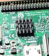
Raspberry Pi 3B is more powerful than Zero, and it needs good cooling. Especially in such a closed case. With a small radiator visible in the photo, after half an hour of playing on any emulator, the core temperature reached 80 degrees and trotting began.
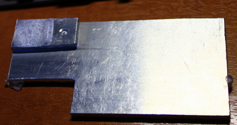
A centrifugal fan of 40 * 30 * 10 mm was ordered, but before it arrived, I just tried to cut a small plate from a 3 mm aluminum plate, measuring 80 * 30 mm. By that time I had dropped all the GPIO pins, so they no longer interfered with the installation of the plate. In addition, I also cut a piece of 20 * 10mm for contact with the chip and made a sandwich from the plates. It exceeded all my expectations, a maximum of 65 degrees on the core.
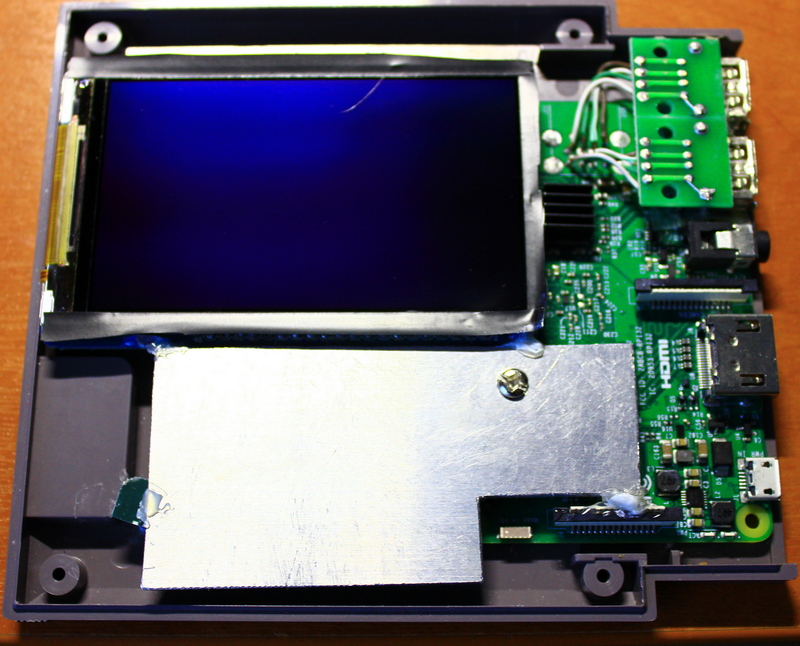
So it looks inside.
In the end, what
How is it played? Fine! With shouts, smashing gamepads, mutual reproaches. Just like sometime.
No delays and lags were noticed.
The screen, of course, is small, only three and a half inches. Five-inch smartphones spoiled us, but you can play. The text is read, even small. I prefer HDMI.
You can come to a friend, play, portability allows. Related accessories: cables, cables, joysticks, charging take up more space than the console itself.
Sound
Unfortunately, the regular sound of the Raspberry Pi leaves much to be desired. PWM modulation with passive filtering is applied as a sound system. Therefore, a USB DAC for PCM2704 was purchased. Mostly because of its size.
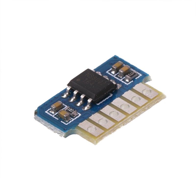
There is a lack of sound output when playing on a small LCD screen, so a 3W microamplifier on the NS8002 was also bought and the speaker from the 8 Ohm tablet was picked up.
USB DAC and NS8002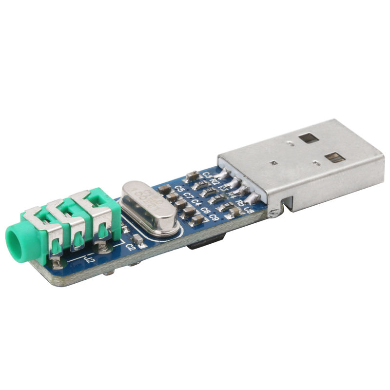
All this will fit under the LCD screen. Come, I will set.
Sawing Retropie
The build is over. Below are some less interesting for entertaining reading features of the settings Retropie.
Shaders
Most consoles that Raspberry Pi is able to emulate have a resolution of 320x240 pixels. By today's standards it is very small. All games acquire pronounced pixelation on modern screens.

The creators of Retroarch, which is part of Retropie, have attended to this issue and added support for shaders. For example, I really like the pre - installed xbr-lv1-noblend.glslp . He literally pulls the details out of the picture. See below.
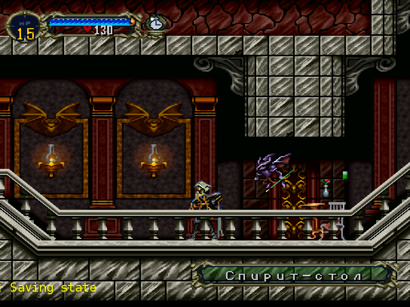 Screenshot from Castlevania: Symphony of the Night game, I advise you to play it
To install a shader, go to the menu Retropie -> Configuration editor . Select Configure basic libretro emulator options , then select Configure default options for all libretro emulators . Then set the Video Shader Enable to “true” and the Video Shader File to the desired shader. Also set Video Smoth to "false", as it only blur the picture. You can even choose something like a scanline shader that emits CRT TVs. But this is an amateur.

Shader rendering is a costly operation. With a resolution equal to and above 720p, quite noticeable jams appear on the RPi 3B. Therefore, in the same menu, select Render resolution "800x600". Do not worry if you have made changes in the /boot/config.txt file, as in this article a little higher, then the screen resolution for the HDMI cable will be 1080p, but the emulator will render the image at 800x600 and stretch it to full screen. And he does it not bad. At least, with the shader is better than without it, and the render in 1080p is useless, because the video data of the game is still drawn for a resolution of 320x240.
The creators of Retroarch, which is part of Retropie, have attended to this issue and added support for shaders. For example, I really like the pre - installed xbr-lv1-noblend.glslp . He literally pulls the details out of the picture. See below.
To install a shader, go to the menu Retropie -> Configuration editor . Select Configure basic libretro emulator options , then select Configure default options for all libretro emulators . Then set the Video Shader Enable to “true” and the Video Shader File to the desired shader. Also set Video Smoth to "false", as it only blur the picture. You can even choose something like a scanline shader that emits CRT TVs. But this is an amateur.
Shader rendering is a costly operation. With a resolution equal to and above 720p, quite noticeable jams appear on the RPi 3B. Therefore, in the same menu, select Render resolution "800x600". Do not worry if you have made changes in the /boot/config.txt file, as in this article a little higher, then the screen resolution for the HDMI cable will be 1080p, but the emulator will render the image at 800x600 and stretch it to full screen. And he does it not bad. At least, with the shader is better than without it, and the render in 1080p is useless, because the video data of the game is still drawn for a resolution of 320x240.
Setting the joysticks
If you have any xinput gamepad (Micro $ oft standard), it will do. It is configured at the first launch of Retropie, or via the start button - Configure Input. But there is a headache. Gone overseas guys, so as not to fall on patent lawsuits, swapped the buttons with A and B, X and Y.

If you have a xbox or similar gamepad, then you need to configure it with inverted buttons, as in NES. Then go to Retropie -> Retropie Setup , select Configuration / tools , then emulationstation , put in Swap A / B Buttons in ES "Swapped". Then reconfigure the joystick.
Also, I do not like how the developers of Retropie disposed of a push-button fund. Where is the combination of buttons to make a screenshot? Why do I need the reset button if I hit it every time? Where are the rewind and speed buttons?
To fix this, you need to edit the file with the name of your joystick in / opt / retropie / configs / all / retroarch-joypads / . It is also available on the \\ 192.168.x.xxx \ configs \ all \ retroarch-joypads \ network. After each update of Retropie through the update, the numbering of the binding flies, so I will not upload the whole config. I will write that changed only these buttons. They are executed when pressed simultaneously with Hotkey, usually a button with a logo in the middle of the joystick.
Here the screenshots button is assigned instead of reset. Fast forvard and rewind (rewind) are configured on the cross buttons: forward and back. The cross and up buttons change the save slot.
Rewind must be enabled in the /opt/retropie/configs/all/retroarch.cfg config. Just do not turn on Rewind on the psx emulator, everything starts to slow down wildly. Rewind, by default, is disabled in the psx config.
I also want to add about Bluetooth. I myself do not like wireless joysticks and always play with the cable. Old school yet. For fans of wireless joysticks, you need to purchase a Bluetooth dongle and plug it into the USB port. It will be better and there will be no problems. I did not check it myself, but knowledgeable people write.
But that's not all. In Retropie Setup , you can put various ports in the package manager, for example, Openttd, Doom, or even a DOS Dosbox emulator. But to control the joystick in them will not work. Only the keyboard and mouse. To fix this, you need to install the xboxdrv driver in the package manager, which can emulate keyboard presses. Just put from source, autorun does not need to do, it does not fit all joysticks.
Launch the script we will write ourselves under our gamepad. Add the following lines to /opt/retropie/configs/all/runcommand-onstart.sh at the end of the file.
Here, $ 1 is our target system, under which xboxdrv runs. You can add by analogy. The lines --evdev-absmap --evdev-keymap are responsible for linking axes and buttons to your joystick. The script above is given for the Xbox One S controller. To find out which axis and button correspond to the number or name of your joystick, you need to type the command evtest in the console. At the same time, you can see which event corresponds to our joystick. I have this / dev / input / event0 which is in the parameter --evdev.
Parameters --ui-axismap emulate mouse axes, and --ui-buttonmap keyboard buttons. In this example, the trigger is the mouse button, the left stick is the mouse, the right stick is the cursor keys. Start, select - enter and esc, respectively. The rest of the buttons are attached keyboard numbers. Unfortunately, it was not possible to engage the crosspiece under the keyboard buttons. For some reason, the Xbox One S joystick refuses to work.
With such a config, strategies are perfectly played, like Theme Hospital, OpenTTD, etc. Shooters are played a little worse, but you can create similar launch scripts for shooters in the same file, changing the $ 1 parameter there.
To ensure the normal operation of the joystick in the emulationstation, you must complete the xboxdrv after exiting the game. To do this, add the following to the end of the /opt/retropie/configs/all/runcommand-onend.sh file.
If you have a xbox or similar gamepad, then you need to configure it with inverted buttons, as in NES. Then go to Retropie -> Retropie Setup , select Configuration / tools , then emulationstation , put in Swap A / B Buttons in ES "Swapped". Then reconfigure the joystick.
Also, I do not like how the developers of Retropie disposed of a push-button fund. Where is the combination of buttons to make a screenshot? Why do I need the reset button if I hit it every time? Where are the rewind and speed buttons?
To fix this, you need to edit the file with the name of your joystick in / opt / retropie / configs / all / retroarch-joypads / . It is also available on the \\ 192.168.x.xxx \ configs \ all \ retroarch-joypads \ network. After each update of Retropie through the update, the numbering of the binding flies, so I will not upload the whole config. I will write that changed only these buttons. They are executed when pressed simultaneously with Hotkey, usually a button with a logo in the middle of the joystick.
Button config
input_screenshot_btn = "0" input_rewind_btn = "h0left" input_hold_fast_forward_btn = "h0right" input_state_slot_increase_btn = "h0up" input_state_slot_decrease_btn = "h0down" Here the screenshots button is assigned instead of reset. Fast forvard and rewind (rewind) are configured on the cross buttons: forward and back. The cross and up buttons change the save slot.
Rewind must be enabled in the /opt/retropie/configs/all/retroarch.cfg config. Just do not turn on Rewind on the psx emulator, everything starts to slow down wildly. Rewind, by default, is disabled in the psx config.
I also want to add about Bluetooth. I myself do not like wireless joysticks and always play with the cable. Old school yet. For fans of wireless joysticks, you need to purchase a Bluetooth dongle and plug it into the USB port. It will be better and there will be no problems. I did not check it myself, but knowledgeable people write.
Xboxdrv
But that's not all. In Retropie Setup , you can put various ports in the package manager, for example, Openttd, Doom, or even a DOS Dosbox emulator. But to control the joystick in them will not work. Only the keyboard and mouse. To fix this, you need to install the xboxdrv driver in the package manager, which can emulate keyboard presses. Just put from source, autorun does not need to do, it does not fit all joysticks.
Launch the script we will write ourselves under our gamepad. Add the following lines to /opt/retropie/configs/all/runcommand-onstart.sh at the end of the file.
runcommand-onstart.sh
# xboxdrv sudo killall > /dev/null 2>&1 xboxdrv if [ "$1" = "pc" ] || [ "$1" = "openttd" ] || [ "$1" = "doom" ] || [ "$1" = "kodi" ]; then sudo /opt/retropie/supplementary/xboxdrv/bin/xboxdrv > /dev/shm/runcommand.log 2>&1 \ --evdev /dev/input/event0 \ --silent \ --detach-kernel-driver \ --force-feedback \ --mimic-xpad \ --trigger-as-button \ --evdev-no-grab \ --evdev-absmap ABS_X=x1,ABS_Y=y1,ABS_RX=x2,ABS_RY=y2,ABS_HAT0X=dpad_x,ABS_HAT0Y=dpad_y \ --evdev-keymap KEY_#304=a,KEY_#305=b,KEY_#307=x,KEY_#308=y,KEY_#312=lt,KEY_#313=rt,KEY_#310=lb,KEY_#311=rb,KEY_#317=tl,KEY_#318=tr,KEY_#314=back,KEY_#315=start,KEY_#316=guide \ --axismap -Y1^deadzone:3000=Y1,-Y2^deadzone:3000=Y2 \ --ui-axismap x2^deadzone:3000=KEY_LEFT:KEY_RIGHT,y2=KEY_UP:KEY_DOWN \ --ui-axismap x1^deadzone:3000=REL_X:06,y1=REL_Y:06 \ --ui-axismap dpad_x^deadzone:0=KEY_LEFT:KEY_RIGHT,dpad_y^deadzone:0=KEY_UP:KEY_DOWN \ --ui-buttonmap rt=BTN_LEFT,lt=BTN_RIGHT,start=KEY_ENTER,back=KEY_ESC,tl=KEY_4,tr=KEY_5,lb=KEY_2,rb=KEY_3,a=KEY_SPACE,b=KEY_M,x=KEY_3,y=KEY_LEFTCTRL,guide=KEY_Y \ & fi Here, $ 1 is our target system, under which xboxdrv runs. You can add by analogy. The lines --evdev-absmap --evdev-keymap are responsible for linking axes and buttons to your joystick. The script above is given for the Xbox One S controller. To find out which axis and button correspond to the number or name of your joystick, you need to type the command evtest in the console. At the same time, you can see which event corresponds to our joystick. I have this / dev / input / event0 which is in the parameter --evdev.
Parameters --ui-axismap emulate mouse axes, and --ui-buttonmap keyboard buttons. In this example, the trigger is the mouse button, the left stick is the mouse, the right stick is the cursor keys. Start, select - enter and esc, respectively. The rest of the buttons are attached keyboard numbers. Unfortunately, it was not possible to engage the crosspiece under the keyboard buttons. For some reason, the Xbox One S joystick refuses to work.
With such a config, strategies are perfectly played, like Theme Hospital, OpenTTD, etc. Shooters are played a little worse, but you can create similar launch scripts for shooters in the same file, changing the $ 1 parameter there.
To ensure the normal operation of the joystick in the emulationstation, you must complete the xboxdrv after exiting the game. To do this, add the following to the end of the /opt/retropie/configs/all/runcommand-onend.sh file.
runcommand-onend.sh
sudo killall > /dev/null 2>&1 xboxdrv If something went wrong when updating Retropie
Once, I launched the Retropie update and when unpacking the kernel, the built-in Wi-Fi fell off. The device was loading, but did not respond to any buttons, including on the connected keyboard. There is no SSH, since there is no Wi-Fi, it does not respond to the keyboard, and the SD card is not accessible ...
I noticed that the keyboard works when loading. Pressed ctrl + c many times and, oh, the console! But now how to restore Wi-Fi? The wlan0 interface was absent from the word at all. Running the update did not help, because it pulls files from the Internet.
First of all, in /opt/retropie/configs/all/autostart.sh commented out the start of the emulationstation and rebooted. After the restart, the console is loaded, the keyboard is working. , wlan . . .
sudo dpkg --configure -a To make Retropie not look like a Linux station
Linux. .
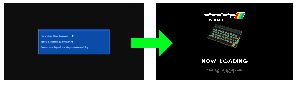
, — splashscreen. , . \\192.168.x.xxx\splashscreens, Retropie -> SPLASH SCREEN -> Append Splashscreen to list .
, , .

Retropie runcommand, . .
, , .
Linux
Linux, /boot/cmdline.txt . .
, , , .
motd.
.
On
.
cmdline.txt
dwc_otg.lpm_enable=0 console=tty3 root=PARTUUID=f2d3cb4f-02 rootfstype=ext4 elevator=deadline fsck.repair=yes rootwait loglevel=3 consoleblank=0 plymouth.enable=0 quiet vt.global_cursor_default=0 plymouth.enable=0 plymouth.ignore-serial-consoles splash , , , .
motd.
nano /etc/motd .
sudo nano /etc/systemd/system/autologin@.service ExecStart=-/sbin/agetty --autologin pi --noclear %I $TERM On
ExecStart=-/sbin/agetty --skip-login --noclear --noissue --login-options "-f pi" %I $TERM .
, — splashscreen. , . \\192.168.x.xxx\splashscreens, Retropie -> SPLASH SCREEN -> Append Splashscreen to list .
, , .
Retropie runcommand, . .
, , .
What else can you do
Improve can be infinite. I will give a couple of links that you can do. Write more interesting things to add. Thanks for attention.
- Install dosbox and various ports .
- Put different themes emulationstation.
- Share the screenshots folder.
- Install a web browser.
- Install Retropie Web Manager
- Link Raspberry Pi with the main computer Steam.
- Install Brutal Doom, finally.
He is worth it.
Source: https://habr.com/ru/post/422005/
All Articles