Underwater "GPS" on two transceivers
Hello, dear reader!
Our underwater GPS has recently turned three years old. During this time, the system became serial, we brought several more systems and devices to the market, but all this time I didn’t leave the obsession to bring underwater acoustics to the masses, to make it accessible to simple amateurs, modellers, representatives of such direction as
And today, in honor of our humble anniversary, I will explain in detail and on the fingers how to determine the geographical position of the underwater object with the help of only two transceivers: with the source code, funny pictures, graphs and the results of experiments.
I ask all interested to us on a canoe, in clean and warm waters of the Volgograd Reservoir!
')

ATTENTION: the article contains trace amounts of matane!
For those who do not understand what is happening, but do not mind to penetrate, I suggest to get acquainted with our previous publications on the subject of underwater acoustics and underwater navigation:
Session video transmission sound through the water with the exposure
Underwater GPS from scratch for the year
Underwater GPS: continued
On the effect of cyanobacteria on the speech functions of the president
Navigation under water: pelenguy - not pelenguy, you are doomed to success
And also with a great review article akuzmin about hydro-acoustics
Introductory
Under water, radio waves do not extend to any significant distance, and more or less decent wireless communication and navigation there, hand on heart, is possible only with the help of acoustics.
There are only two and a half working types of navigation systems:
- ultrashort-base (UKB, USBL) - based on determining the angle of arrival of the beacon signal and measuring the distance (either by the method of request-response or by synchronized clock). The angle of arrival is determined using an antenna array. The desired position is determined by the angle and distance (direct geodesic task). Ukb system for example, is our ZIMA
- long basic (dB, LBL) - where the arrival times of a signal are measured either at several receivers, or from several transmitters (our underwater GPS works exactly like this) with a known position. You can either measure the distance by the method of "request-response" (distance measuring method) or measure the difference in arrival times of a signal (difference-distance measuring method), for example, GPS and GLONASS work. The long base can be floating (like our RedWAVE ) or bottom.
- Shortbase (KB, SB) - in fact - the same long-base systems, but all the supporting elements of the base are located on the same basis - for example, on a ship.
As I have already said, a long base can work on the principle of "request-response", in this case it is required to solve the problem of intersection of N spheres, or circles, if the depth of the desired object is known.
Or the base can work just like GPS and GLONASS, such systems are also called hyperbolic, and this is why: if the target object periodically emits a navigation signal, and the clocks of all receivers (base elements) are synchronized, then the distance cannot be measured directly, but you can only find out Which of the base elements is the source closer or farther away. That is, in the presence of only the difference of distances. And as is known from the school course:
"Hyperbola can be defined as the locus of points, the absolute value of the difference of the distances from which to two given points, called foci, is constant"
In other words, if the underwater object emitted a signal, and we received it on two receivers, the clocks of which are synchronized, then we can assert that our object lies on the hyperboloid (or on the hyperbola, if he suddenly gave us his depth). More receivers - more hyperbole! More hyperbole - higher positioning accuracy;
And if it is not the underwater object that radiates, but the elements of the base, then the underwater object, knowing its depth, can determine its location itself, and moreover, it does not interfere with anyone in this case and there can be as many such objects as they are just listeners. That's the way GPS / GLONASS and our RedWAVE are .
And I promised to navigate through two transceivers, one of which is the one whose position is just to be determined.
Let's understand
Distance between two points and in three-dimensional space is determined (you never know, suddenly someone forgot) by a simple formula:
Suppose we have N base stations. From humane considerations suppose that their coordinates are known to us, and we measured the distances from each of the base stations to target T. For clarity: T is the target, and B is base.
Therefore, we can for any point write an expression that shows how this point fits our experimental measurements. In fact, this will be the sum of the differences between the distance from point M to the corresponding base station and the measured distance. Each difference will be squared.
In general, the case goes to the least squares method, and the coordinates of the desired point ideally should be the minimum of the function ε.
If we are talking about the difference-distance method, which we touch on this article completely indiscriminately, and we have each base station corresponds to an unmeasured distance and the time of arrival of the signal , then in the expression of the error function there will be not differences, but their differences. The only difference is that you will have to sort out the necessary pairs of base stations, for example, for the nth and n + 1st stations:
v - here means the speed of sound, which, by the way, is not constant, but strongly depends on the density of the medium, read, on temperature, salinity and pressure. And if you want to do everything in an adult way, then you need to either directly measure it, or count, but about this some other time.
Note that the depth of positioned objects in modern hydroacoustic navigation systems is measured directly and with a sufficiently high accuracy (0.5-2 cm), which means that the task makes sense to translate into a flat one.
It would be possible to inform that now we are solving this with any method of optimization and finish it. But, firstly, not everything is so simple, and secondly, not everything is so difficult.
Let's start with the difficulties
The fact is that a lot depends on the arrangement of base stations relative to each other (this can somehow be influenced, for example, by administrative methods =) and the position of the positioned object, relative to the base elements (this is much more difficult to influence, in a wide range of tasks initially the position of the object being positioned is known very roughly and it is almost impossible to establish a base in advance).
Get the situation as in Figure 1 - like a good morning:
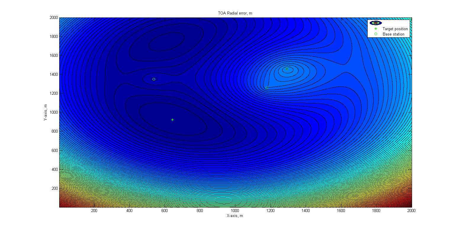
Figure 1 - Error surface for the base of their three elements. Positioned object out of base. Presence of a false minimum
The green circles indicate the positions of the base stations, and the asterisk indicates the true position of the object being positioned. The color of the points indicates the magnitude of the residual function (ε) at this point. As one politician said, it is completely understandable that the surface has two depressions, and when searching for a minimum it is very easy to fall into a false one. The situation turns out to be even worse: taking into account the scale, the real position of the object and the average speed of movement of such objects, we can say that it will be in such a position for a long time, the shape of the error surface will remain, and the likelihood of the object location will be very long .
The animation below illustrates a similar situation - and when starting a search from a midpoint between base stations, and when starting from a nearby station, the search leads to a false minimum:

Figure 2 - Search hit to a false minimum when starting from the midpoint of the base. Base of three elements
The search here is implemented using the Nelder-Mead algorithm , or as it is also called, the simplex method. That it is used, for example, in Matlab in the fminsearch function
It does not require the calculation of derivatives, is very intuitive, intuitive and easy to implement.
Figure 3 - Search hit to the false minimum when starting from the nearest base element. Base of three elements
Knowledgeable people may be indignant that no one puts base stations on the line, but, firstly, sometimes they do, and secondly, this is an exaggeration for a more visual demonstration.
“The defeat was complete. It was not possible to invent something ”(C) A. and B. Strugatsky,“ The City of the Doomed ”
What can you think of here?
Logic suggests that you can use one of two methods of global optimization - Simulated Annealing or something similar. However, another (and more productive) approach is to more fully use a priori information to select the starting point of the search.
After all, we know for sure that the desired point lies (with a share of assumptions) on the circles, in the centers of which the base stations are located, and the radii of these circles correspond to the measured distances!
And we are sure that the error in measuring the distance in sonar increases with this range: the sound propagates nonlinearly.
You can take and try to choose the starting point of the search for a minimum around (literally, on a circle) of the nearest lighthouse, expecting that the distance to it is measured with maximum accuracy, and guided by the same value of the residual function ε.
The coordinates of the candidate points are formed in this case according to the following simple formulas:
and - coordinates of the near (c - closest) base station, - distance from it to the object being positioned. - argument (angle). If we now search for at least varying in the range from 0 to 360 degrees in increments of, for example, 10 degrees, and then search near this value by reducing the step to 1 degree and narrowing the search area to 20 (± 10) degrees, you can very well determine the initial approximation, which is practically in all cases, immediately hits almost exactly the target!
In the pictures below, the 30-iteration “head-on” solution method gallantly fell into a false minimum, which led to an absolutely wrong decision, and the method with preliminary one-dimensional minimization almost immediately hit the spot and in 6 iterations approached the actual position with a difference of ~ 25 centimeters at distance to the nearest base station ~ 400 meters.
Figure 4 - Search hit to false minimum

Figure 5 - Finding the right solution when starting from a point obtained by preliminary one-dimensional minimization
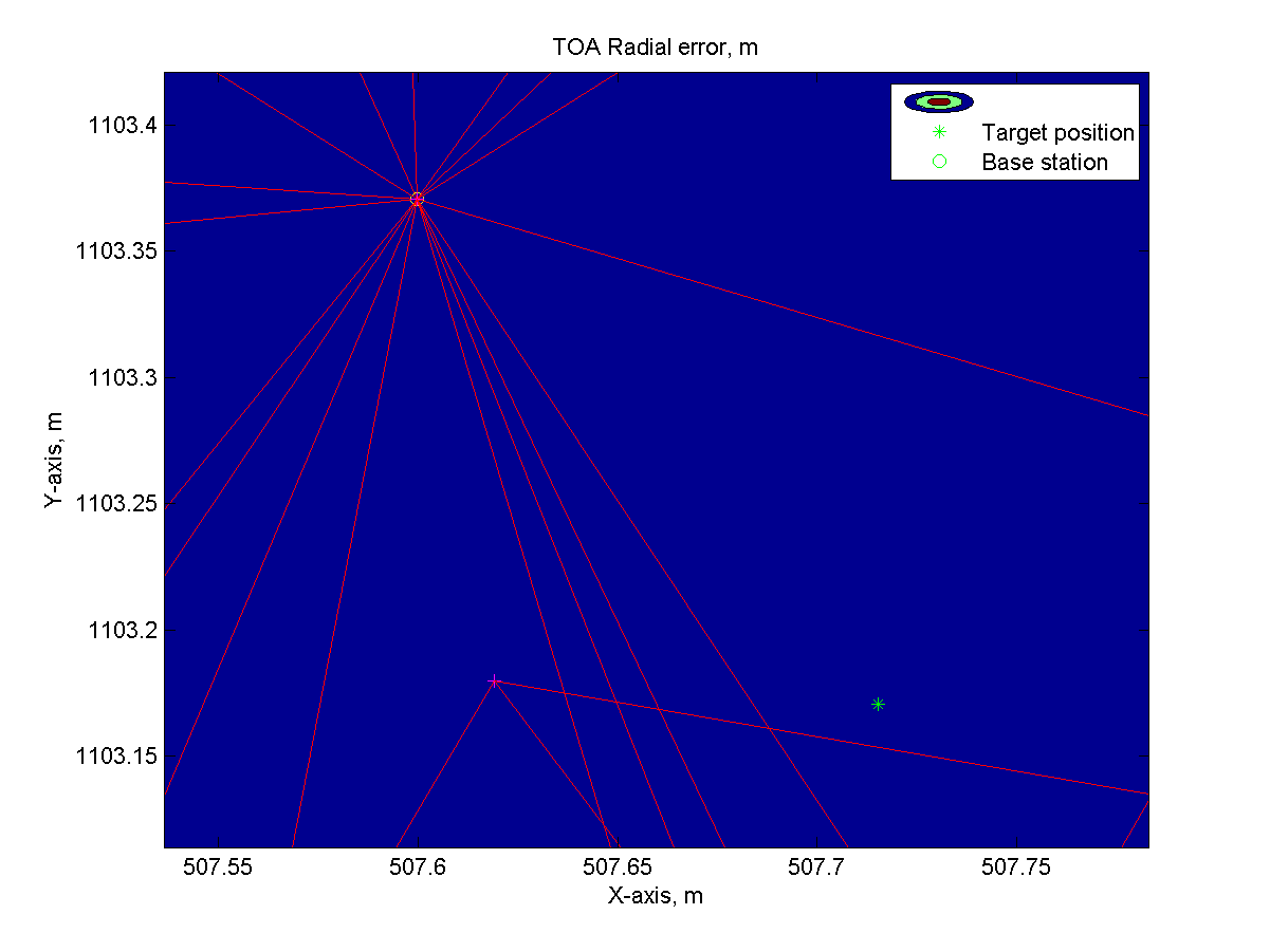
Figure 6 - Enlarged area around the solution obtained. The yellow circle is the resulting solution, the green asterisk is the true position of the object
In the above example, the first iteration after a preliminary selection of the initial search position gave a solution 20 meters from the real position (on the field ~ 600x600 meters).
At this stage, we dealt with the distance-measuring method, with the difference-distance-measuring situation a bit more complicated: there are no such clear guidelines for choosing the starting point (the circle is a good figure because it is closed, and the hyperbola is bad because it goes to infinity).
Let's return to the promised “underwater GPS” of two transceivers. In a sense, I was certainly a goof: a full-fledged underwater GPS would not work out of our first article , but if you
Often the positioned object is fixed (well, or at least moves negligibly slowly). In such cases, instead of several base stations, you can actually use one, but moving: this approach is called VLBL or virtual long base. If we do not need to fix the track of the movement of the underwater object, but simply to determine its location - this is what we need.
Often this task arises when installing any bottom equipment by free dumping from the vessel. With tangible depths and the presence of currents, the actual position of the equipment at the bottom may differ significantly from the position of the point where it was dropped. This equipment may be an element of the bottom navigation base: to determine the location of the underwater object, you must first determine the location of the underwater object.
So how can this all be arranged in the real world?
Our experimental set-up consists of:
- an object that we will hide at the bottom of the reservoir: our RedGTR code modem is in a standalone version (this only sounds official, in fact, a modem connected to a sealed battery box); Here it is in the photo:

Figure 7 - A battery canister beacon - Mobile base station on the basis of Chinese bait boat from our other article . In addition to the native control, she has a second RedGTR modem, a 433 MHz DORJI radio module with an antenna, a self-made GPS / GLONASS module based on quectel l76, and an own board based on STM32F429 (can be easily replaced with NUCLEO-STM429 or STM32F4 Discovery I am sure that any Arduino-like card would also do it) which simply plays the role of a router: everything goes from the radio channel via UART to the modem and vice versa, the data from the GPS module also pours into the radio channel.
So it looks in the collection:
Figure 8 - Photo of the test craft assembly
This time we put on some kind of transom for fastening a bar with a modem, the experience of a freely towed navigator revealed the viciousness of such a scheme both in terms of manageability and in terms of the changing mutual arrangement of the device and the boat.
So everything looks in the hold: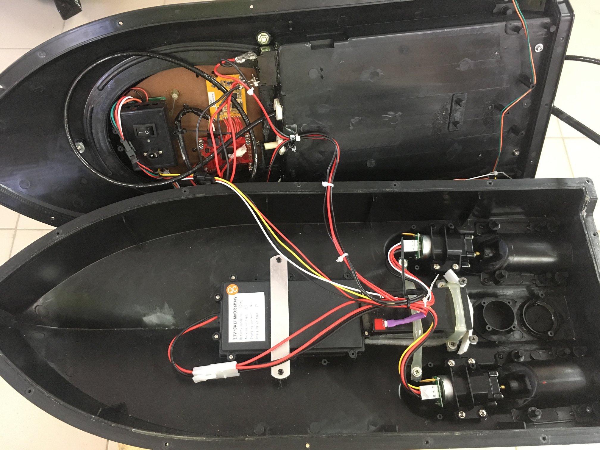
Figure 9 - Photo of the test craft. View of the hold
All native circuits remained almost unchanged, and all additional equipment is powered by a separate lead battery at 1.2 Ah. - operator's console, which includes a laptop with software and a response radio module connected via a converter to USB. The software is of course somewhat hasty and only suitable for demonstration, but a modem interaction protocol, a TOA-solver based on the same Nelder – Mead method, selection of base points, a simple drawing of geographical positions and the possibility of GPS emulation for transmitting data to any analog of google earth.
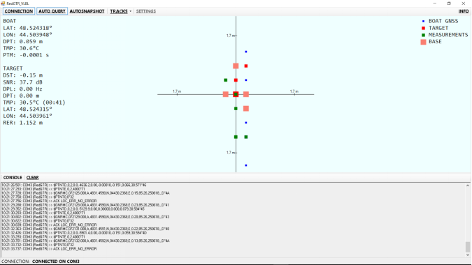
Figure 10 - “Operator Console”. Test run on the table.
The blue dots are the positions of the boat using GPS, the green ones are the positions at which measurements were made, the positions of the elements of the virtual base are highlighted with salmon, the calculated beacon-responder positions are shown in red.
Who is busy?
- the modem to be found simply lies on the bottom, receives and responds to requests;
- a modem that is on the boat, executes commands that come through the UART - sends requests and receives responses, which is reported by UART
- the board with the STM32F4 in the boat receives data from the GPS and modem via the UART and redirects them to the radio module via another UART, and it redirects the data from the radio module to the modem; There is a small nuance associated with the radio module - it is not full duplex (just like in sonar =)), so the board “holds” the RMC message from the GPS module and sends it only along with the message from the modem;
- the console software controls the entire action, collects data on distances to the target from different geographic locations, selects the optimal base and determines the location of the target;
A little more detail
Communication with modems occurs via NMEA-like protocol. For our task, only three messages are used:
$PTNTE,targetAddr,requestedCmd,timeoutMs*hhfrom the remote to the modem. Send the
requestedCmd command to the remote subscriber at the address targetAddr , set the timeout for the response to timeoutMs.The command can be any of the approved list:
| Team | Code | Description |
|---|---|---|
| CDS_CMD_PING | 0 | PING request to which the remote subscriber answers PONG |
| CDS_CMD_PONG | one | PING Response |
| CDS_CMD_DPT | 2 | Command to the remote subscriber to transfer its depth |
| CDS_CMD_TMP | 3 | Command to the remote subscriber to transfer its temperature |
| CDS_CMD_BAT | four | The command to the remote subscriber to transfer the voltage |
| CDS_CMD_USR_0 | five | User Team 1 |
| CDS_CMD_USR_1 | 6 | User Team 2 |
| .. | .. | .. |
| CDS_CMD_USR_34 | 39 | Custom command 34 |
The modem supports basic functions: ping, depth transfer, water temperature, battery charge, and a set of user code commands.
To the TNTE team, the modem immediately responds to the fact of accepting the command or the inability to execute it with the ASC message:
$PTNT0,errCodeerrCode - 0 if the modem accepted the command, otherwise the error codeIf the modem did not wait for the remote subscriber to respond in time, he reports this with the message
REM_TIMEOUT , containing in the parameters field only the address of the remote subscriber:$PTNTB,targetAddrIf the modem received the response in time, then it reports this with the
REM_PONGEX command, which has the following format:$PTNTD,requestedAddr,requestedCmd,receivedValue_decoded,snrd,dpl,pTime,[dst],[dpt],[tmp]requestedAddr - address of the requested subscriberrequestedCmd - requested commandreceivedValue_decoded - accepted valuesnrd - signal-to-noise ratio at receiver output in dBdpl - Doppler shift in HzpTime - signal propagation time (one way) in secondsdst - distance to the subscriber in metersdpt - modem's own depth in meterstmp - outside water temperature in degrees CelsiusThe last three parameters are transmitted only if the modem is made with a built-in pressure / temperature sensor (our version).
From the GPS module, we are only interested in the RMC message, from where we take the current geographical position (GGA or GLL could also be used - the last one is the shortest).
The most difficult thing is the transmission of data through the water and the measurement of the distance — the modems perform, the determination of the boat’s geographic position — the GPS module;
All parsing and construction of NMEA messages are performed using the NMEAParser class in the UCNLNMEA library.
The console software running on a laptop periodically sends
REM_PINGEX requests to the subscriber at the address specified in the application settings, it does so either upon receipt of REM_TIMEOUT or REM_PONGEX . Along the way, the coordinates of the boat are recorded and data on the distance and depth of the remote subscriber are stored along with the coordinates of the boat in which they were obtained.Common sense (and experience) tells us that in order to determine the position of an underwater object, 3-5 virtual base stations are needed, and as can be seen from the pictures above, they should not be located in any way.
That is, the following task is being formed: as measurements become available, it is necessary to select several of them as elements of the navigation database in a certain way.
I propose the following option: choose such measurements so that they form as convex a shape as possible, described around the intended location of the object being positioned.
To do this, we take a certain point (at the initial stage, when it’s not at all clear where the object is being positioned, the middle point of all measurements will fit, which will then be replaced with the first approximation of the position of the object you are searching for), and calculate the azimuth angle from it (the angle between north point) at each measurement point. And now we will choose several of those that would most evenly cover the resulting range of angles. In the console software, this is done by the method
List<Measurement> Measurements.GetBase(); As data arrives, in the method where the message
REM_PONGEX is REM_PONGEX , REM_PONGEX add measurements and try to build the navigation database and solve the navigation problem with it. The method is responsible for this. GeoPoint3DWE LocateLBL_NLM(List<Measurements> base, GeoPoint3DWE prevLocation, double rErrorThreshold, out double stStageRErr, out int itCnt); The base itself is passed to it - a set of measurements that we selected to solve the navigation task, the previous position (if it is, the depth of the object being searched for), the radial error threshold, and two diagnostic output parameters - the radial error at the first stage of the solution one-dimensional optimization) and the number of iterations, after which the solution was obtained in the second stage.
If the solution we are satisfied with is due to a radial error, then we will use this solution as a reference point for building the base.
And so until you get tired of getting a solution that satisfies us.
The
LocateLBL_NLM method, as can be understood from the name, solves the problem by the Nelder-Meade method , first performing one-dimensional optimization, if there is no previous solution. In reality, it is possible and not to be attached to the previous result, but applying one-dimensional optimization all the time - the strategy may be different and depends on specific conditions.For simplicity, the solution is performed in meters, for which, before the beginning of the solution, all coordinates are transferred to the local system, with a reference point at the midpoint of the navigation base. After solving, the result is converted back into geographic longitude and latitude (longitude is X, and latitude is Y). To convert degrees to meters and back, the Navigation class contains the methods GetDistance2DDeg and Meters2Deg.
But, as you know, the theory without practice is dead, and it is time to move on to the results of field experiments.
Revive theory practical test
According to the old tradition, tests are carried out in the mouth of the river Pichuga . There is a convenient place, there is a depth of almost 30 meters, and a rather complicated water area.
The respondent beacon is fixed on a special “stand” handle (foam rubber bulbs and an anchor, which help the whole structure to stand vertically, did not get into the frame):
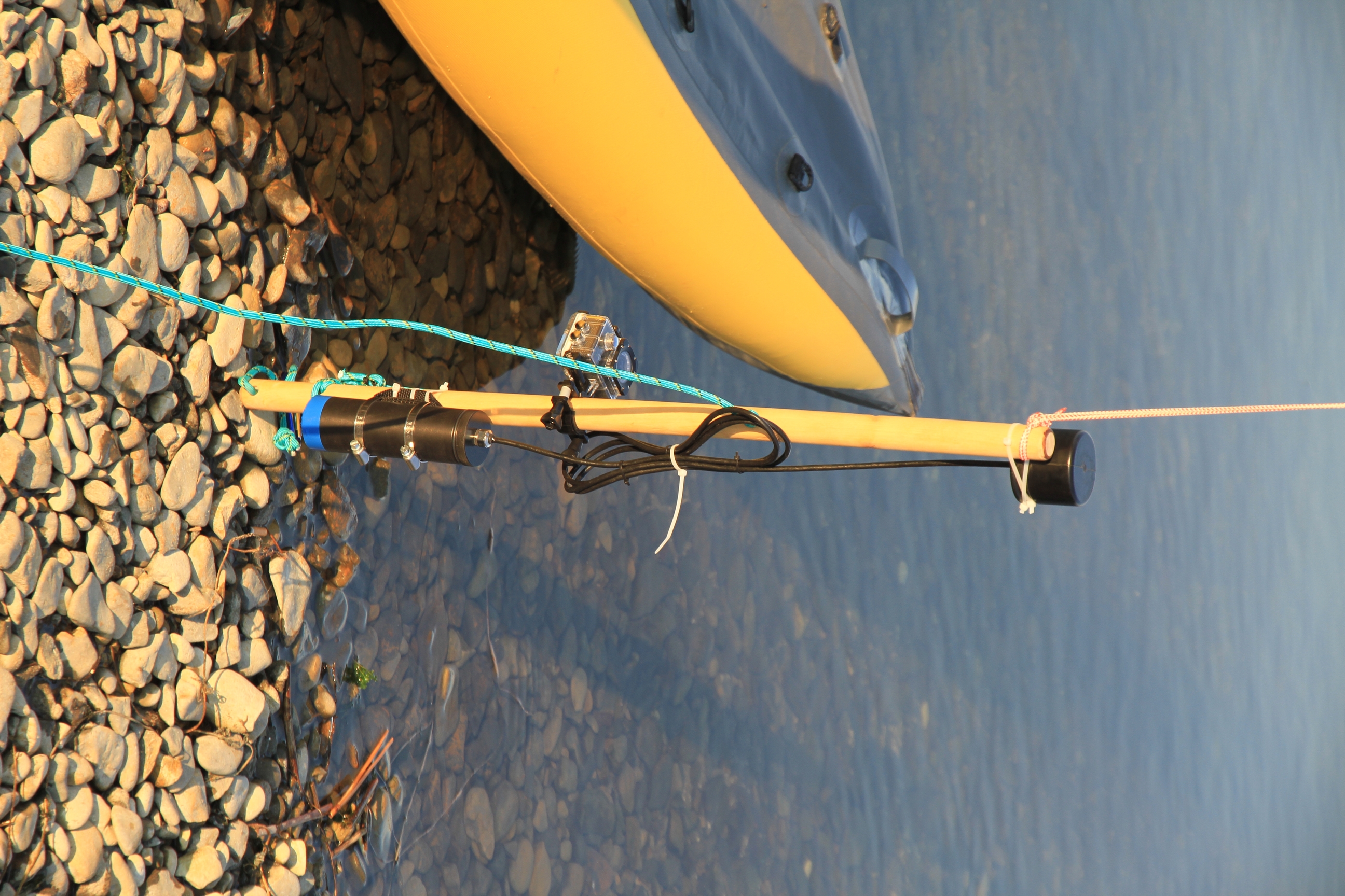
Figure 11 - “Ground Station” responder beacon
The installation of the lighthouse was videotaped , a little miscalculated with the light, and they forgot to take a flashlight with them, so that the moment of contact with the ground remained hidden in the dark.
While going to the test gave the boat a name:

Figure 12 - “Palych” in its natural environment
On the transom “Palych” nylon ties secured a piece from the fishing rod, on which the RedGTR modem is located (so that it does not dangle and pop up).
The experiment was that the respondent beacon is installed on the bottom, only a small float sticks out of it, while “Palych”, controlled from the coast, walks the water area in large circles, the console software periodically requests the respondent for something . All data is recorded in the log, and on the screen everything is displayed according to the real state of affairs. Like this:
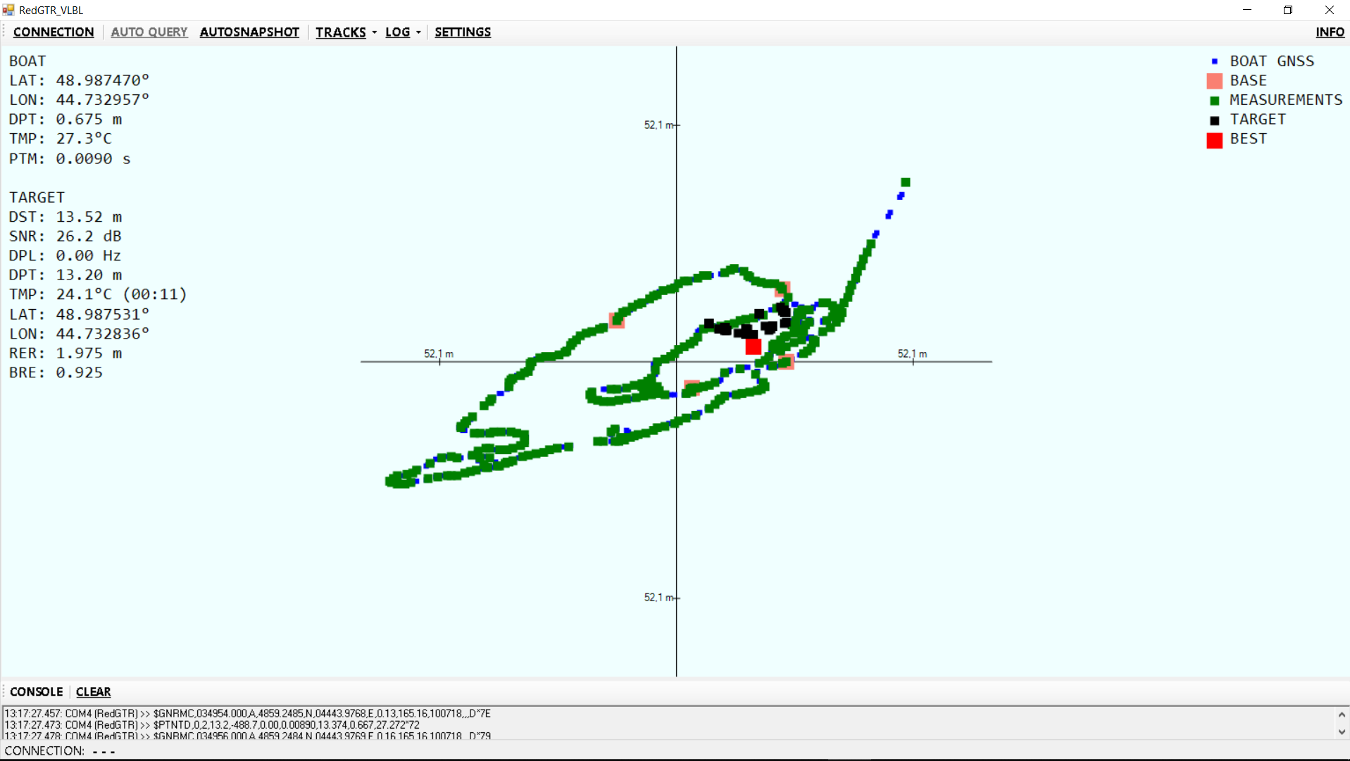
Figure 13 - Screenshot of the console software with boat trajectory and calculated beacon-responder positions (the best calculated position is shown in red)
As can be seen from Figure 13, the lighthouse was located at a depth of 13.2 m, and the water temperature at this depth was 24.1 ° C.
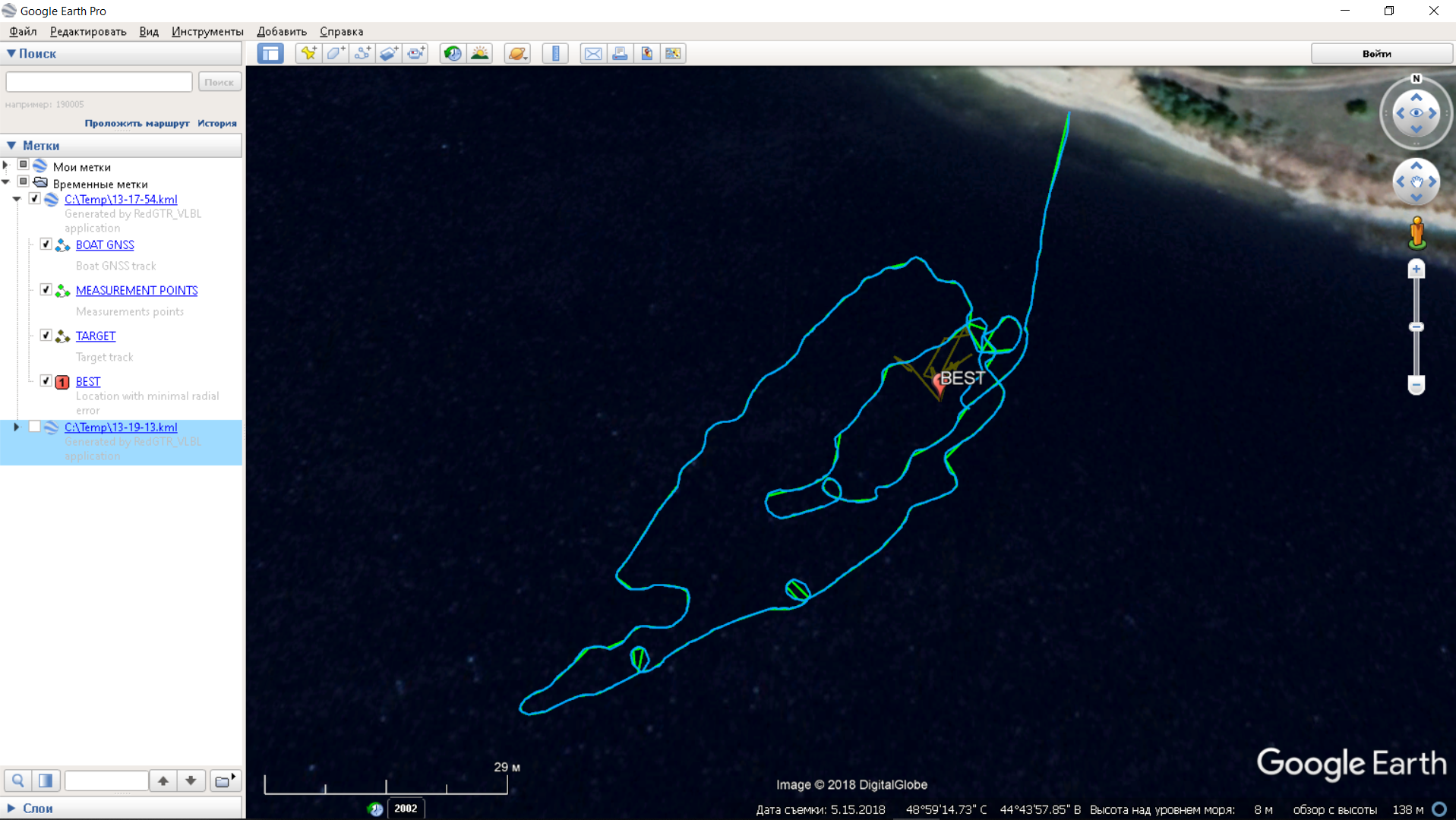
Figure 14 - Import received tracks in GoogleEarth
Getting a good result in this case took about 15 minutes of swimming on the strength.
In the second experiment, the lighthouse was installed at a depth of 16.5 meters, where it was expected to be somewhat colder - just 22.6 ° .
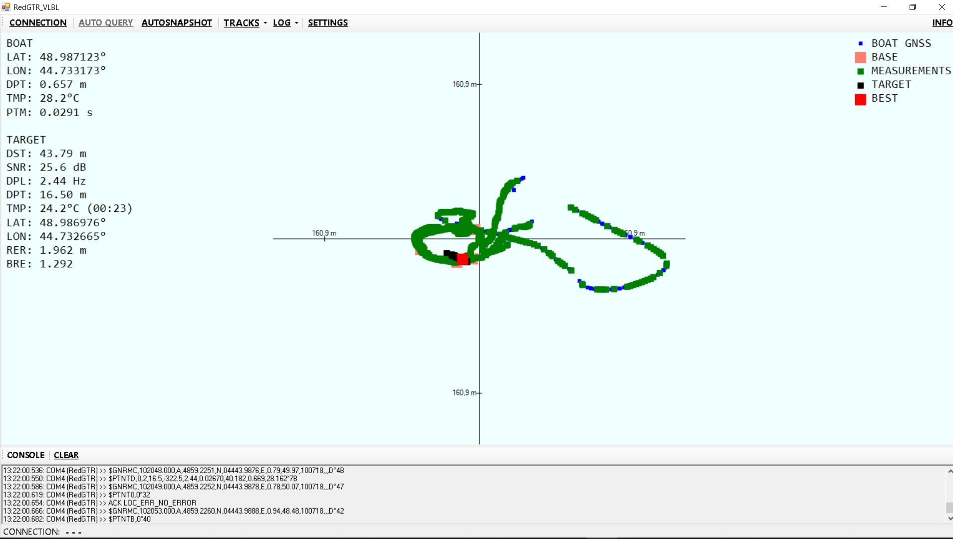
Figure 15 - the result of determining the location of the respondent beacon in the second experiment on the console software screen
In this case, we didn’t deal with the correct assessment of accuracy due to an acute shortage of time (in fact, these amusing tests caused some friction among the management, because they were not working), but were content that when the ship went to the float (this moment can be seen on the first track ), then in terms of its position completely coincided with the best solution, and the distance coincided with the depth (with the difference between the depths of the defendant and the modem installed on the vessel). The points at which the beacons were discharged were recorded, and the discrepancy between the calculated position and the discharge points is in the region of 2-3 meters, which further confirms the efficiency of the system.
In general, it can be stated that this proof-of-concept has been successfully completed!
We received real pleasure and sunburn, we will be happy to answer questions and listen to criticism!
Afterword
The sad fact is that the modems used in this experiment, although very cheap by the standards of the world market for hydroacoustic communications, are not very accessible to amateurs.
In order not to be unsubstantiated, I will give a link to the excellent work of Miss Benson, in which on page 54 of PDF or 36 there is an interesting label on the numbering of the document, with prices for some hydroacoustic modems as of 2010. So it goes. (There is a small error in the table - the range of communication for the modem developed by it is indicated in meters, while in the column heading it is km).
The good news is that we suddenly developed modems that can do almost everything the same (a bit smaller in size (in fact the smallest in the world, and the smallest were ours too - from this article), the communication range is shorter , the transmission rate is lower), and, according to our estimates, are already quite uplifting for wealthy enthusiasts. At the moment, electronics and firmware are fully prepared, and we finish the case solution. At the end of the development we will definitely publish an article with the results of an experimental verification.
Attention! Poll:
Source: https://habr.com/ru/post/421977/
All Articles