How Yandex created augmented reality in Maps for iOS. Experience using ARKit
Fewer people remain who can be surprised by augmented reality (AR). For some, this technology is associated with a toy for a couple of hours. Others find it more practical application.
My name is Dmitry, and I am developing Yandex.Maps for iOS. Today I will tell Habr's readers how we created routing using augmented reality. You will also learn about the features of the use of the ARKit framework, thanks to which the introduction of augmented reality has ceased to be the work of only specialists in the field of computer vision.
In 2009, Esquire magazine was the first among the media publications to add support for augmented reality to its product. On the cover of the magazine posted a code with which you can see Robert Downey Jr. "live".

The use of AR in the field of entertainment is not limited. A striking example was the game Pokemon Go, released in 2016. Already by July of the same year it was downloaded over 16 million times. The success of the game led to the emergence of numerous clones with AR.
Significant events in the AR industry in recent years can be considered the announcements of Google Glass and Microsoft Hololens. The appearance of this kind of device shows the vector in which large companies are moving.
Not an exception, and Apple. In 2017, the company introduced the ARKit framework, the importance of which for the industry can not be overestimated. And we will tell about it in more detail.
ARKit
Features ARKit, thanks to which it became easy to use AR:
- no need for special labels (markers),
- integration with existing frameworks for 2D / 3D graphics from Apple - SceneKit, SpriteKit, Metal,
- high accuracy of determining the position and orientation of the device in space,
- no need to calibrate the camera or sensors.
Under the hood of ARKit is a system of visual inertial odometry, which combines data from the visual (camera) and inertial (accelerometer, gyroscope) subsystems of the device for determining position and displacement on the stage. The connecting element of this system is the Kalman filter - an algorithm that at each moment of time selects the best of the testimony of two subsystems and provides it to us in the form of our position and orientation on the stage. ARKit also has an “understanding” of the scene - we can define horizontal and vertical surfaces, as well as the conditions for the illumination of the scene. Thus, when adding an object to the scene, we can add a default lighting to it, thanks to which the object will look more realistic.
Soon, version 2.0 of the framework will be released, in which new features will be added and positioning accuracy will be significantly improved.
ARKit allowed developers to embed augmented reality of high quality into their applications, while spending much less effort. Let us demonstrate this using the example of Yandex.Maps.
Routing with AR in Yandex.Maps
Usually, after the announcement of the new version of iOS, many teams in Yandex gather to discuss the possibility of introducing new features into their applications. The Yandex.Maps team did the same. Within a month after the announcement of ARKit, we often discussed ways to incorporate it into Maps. How many ideas we have not heard enough from each other! Pretty quickly we came to the conclusion that one of the most useful and lying solutions is the use of augmented reality in routing.
The choice of this idea was due to the fact that many card users often encounter a situation where you find yourself in unfamiliar terrain and need to quickly decide where to go. The standard approach for the average card user is to open the application, build a walking route, and, turning on the spot, determine where to go. The idea of introducing augmented reality into pedestrian routing is to save the user from unnecessary actions by immediately showing where to go right over the image from the camera.
First I want to say a few words about routing. What do I put into this concept? From the point of view of implementation in a mobile application, this is a fairly standard set of steps that allow the user to get from point A to point B:
- selection of points of departure and arrival,
- getting the route as a set of points in geographic (latitude, longitude) coordinates,
- display on the map of the route line,
- accompanying the user with additional information while driving along the route.
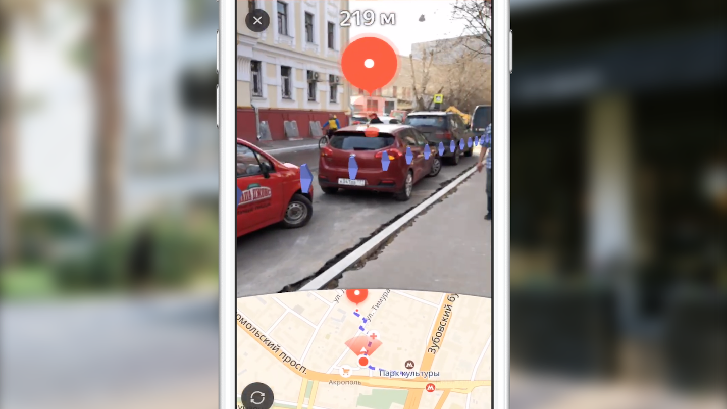
We will not dwell on the first two points. I can only say that we get the route through our cross-platform Yandex.Mapkit library, which is also available to you as a pod. What makes augmented reality routing different from standard routing in maps? First of all, the main difference is the almost completely hidden card. The main focus is on the area of the screen with the image of the video stream from the camera, on which additional visual elements are superimposed (finish mark, auxiliary mark and image of the route line). Each of these visual elements has its own meaning and its own logic (when and how it should be displayed). We will consider the role of each of these elements in more detail later, but for now I propose to consider the tasks that we faced initially:
- learn how to position objects on the ARKit scene, knowing their geographic coordinates,
- learn how to draw the necessary UI on the 3D scene with sufficient performance.
We needed to convert the coordinates of points from geographic to coordinates on the stage, choose which of the points to display, and display the entire UI over the camera image in the correct position. But everything turned out to be a little more complicated than it seemed at first glance.
Before proceeding to the implementation of the feature itself, one of my colleagues was given the task of creating a prototype, showing the possibility (or impossibility) of implementing such functionality with an accessible set of tools. For two weeks, we watched San Sanych plowing the open space and the surrounding area of our office with a phone in hand and viewing the world through the lens of the camera. As a result, we got a working prototype, which showed each point of the route as a tag on the stage with a distance to it. With the help of this prototype, it was possible, under successful circumstances, to walk from work to the subway and almost never get lost. But seriously, he confirmed the possibility of implementing the conceived functionality. But there remained a number of tasks that our team still had to solve.
It all started with the study of tools. At that time, only one person in the team had experience in working with 3D graphics. Let's take a quick look at the tools that anyone who has to think about the implementation of such ideas with the help of ARKit will have to face.
Tools and APIs
The main job of object rendering is the creation and management of scene objects of the SceneKit framework. With the advent of ARKit, the ARSCNView class became available (the successor of the SCNView class is the base class for working with the scene in SceneKit), which solves most of the laborious tasks of integrating ARKit and SceneKit, namely:
- synchronization of the position of the phone in space with the position of the camera on the scene,
- the scene coordinate system is the same as the ARKit coordinate system,
- The video stream from the camera of the device is used as the background of the scene.
The ARSCNView object also provides the developer with an augmented reality session object that can be launched with the necessary configuration, stopped, or subscribe to its various events using the delegate object.
To add objects to the scene, use heirs or directly SCNNode objects. This class represents a position (three-dimensional vector) in the coordinate system of its parent object. Thus, we get a tree of objects on the scene with a root in a special object - the rootNode of our scene. Here, everything is very similar to the hierarchy of UIView objects in UIKit. SCNNode objects can be displayed on the scene when they add material and lighting.
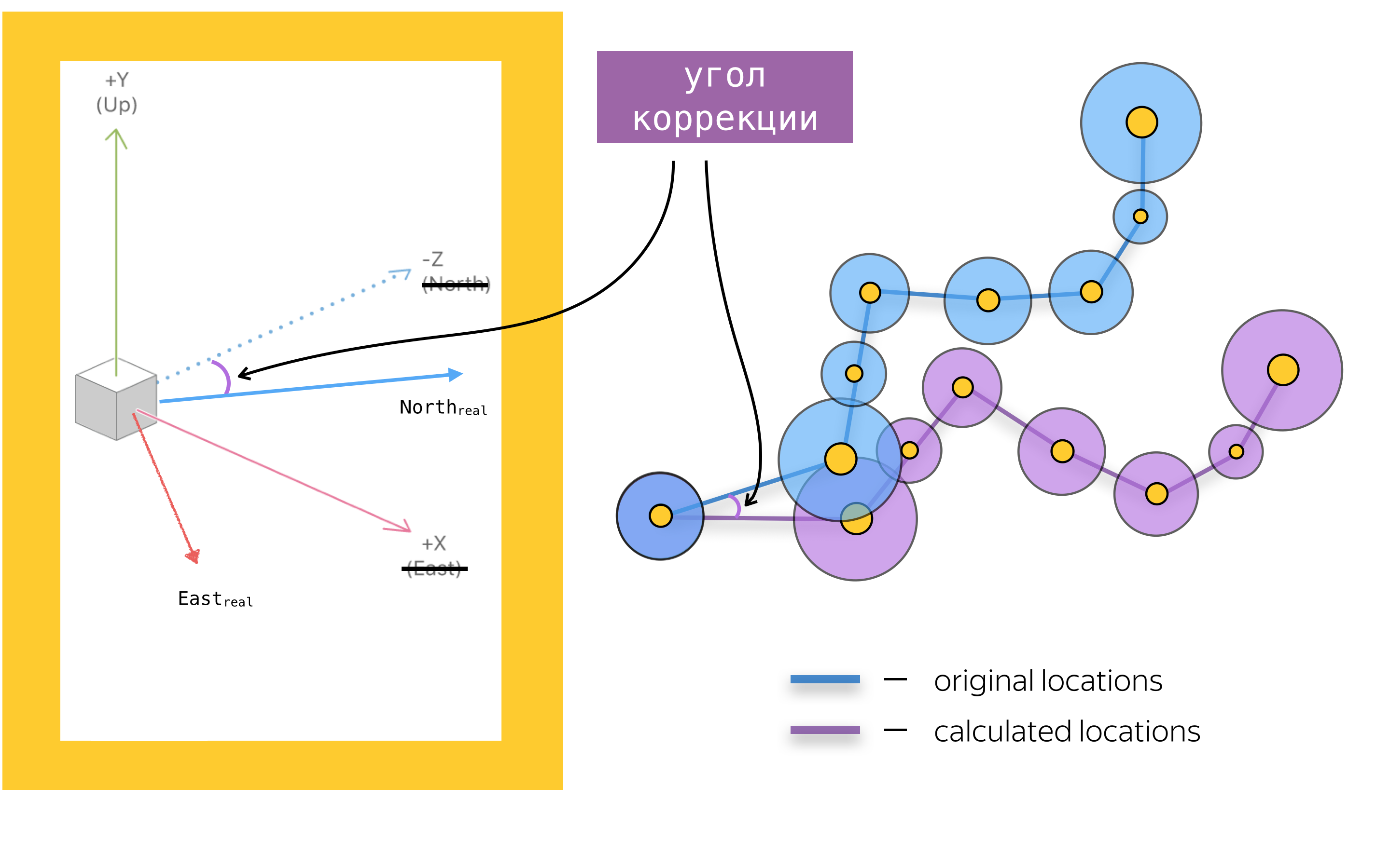
In order to add augmented reality to a mobile application, you also need to know about the main objects of the ARKit API. The main one is the object of an augmented reality session - ARSession. This object performs data processing and is responsible for the life cycle of an augmented reality session. The purpose of this article is not to retell the ARKit and SceneKit documentation, so I will not write about all the available configuration options for an augmented reality session, but I’ll dwell on one of the most important for navigation applications, the configuration option for an augmented reality session - worldAlignment. This parameter determines the direction of the coordinates of the scene axes at the time of session initialization. In general, when initializing an augmented reality session, ARKit creates a coordinate system with the origin at the point that coincides with the current position of the phone in space, and directs the axes of this system depending on the value of the woldAlignment property. In our implementation, the gravityAndHeading value is used, which means that the axes will be directed as follows: the Y axis in the opposite direction of gravity, the Z axis to the south, and the X axis to the east.
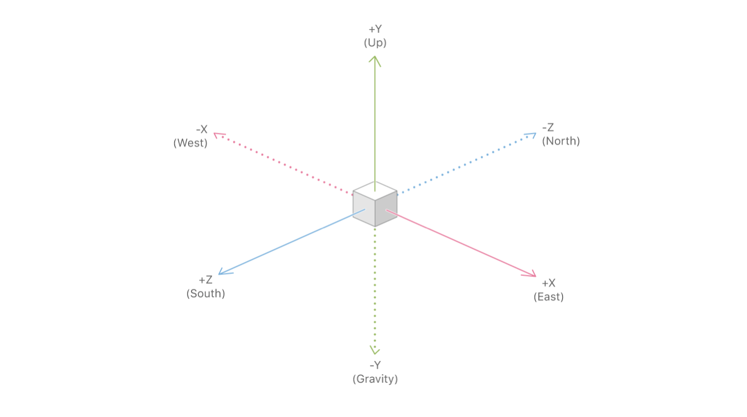
With good luck, the X / Z axis will indeed be aligned with the directions to the South / East, but due to errors in the compass readings, the axes may be directed at some angle to the direction described in the documentation. This is one of the problems that we had to fight, but more on that later.
Now that we have reviewed the main tools, let's summarize: route mapping using SceneKit is adding SCNNode objects to the scene at positions obtained by converting from geographic coordinates to scene coordinates. Before we talk about coordinate conversion and generally about placing objects on the scene, let's talk about the problems of drawing UI elements, assuming that we know the positions of objects on the scene.
Finish line
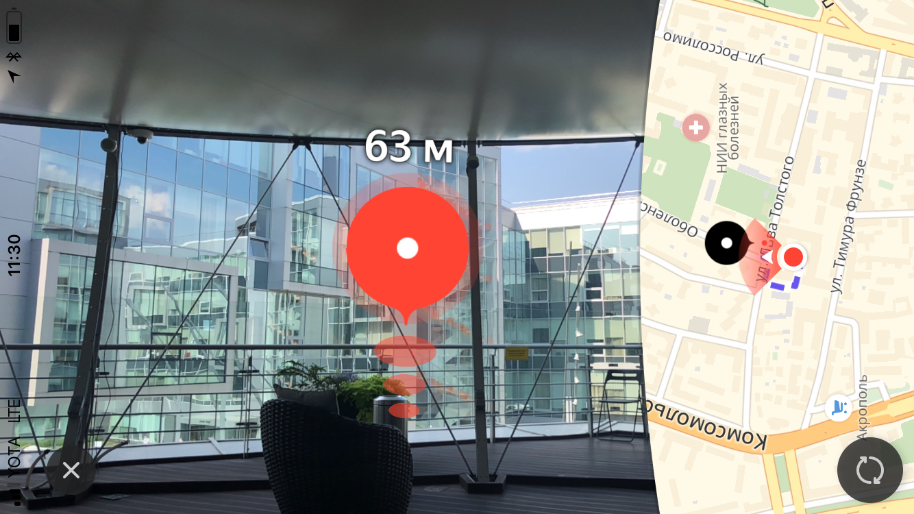
The main visual element of pedestrian routing with augmented reality is the finish mark, representing the end point of the route. Also above the label, we show the user the distance to the end point of the route.
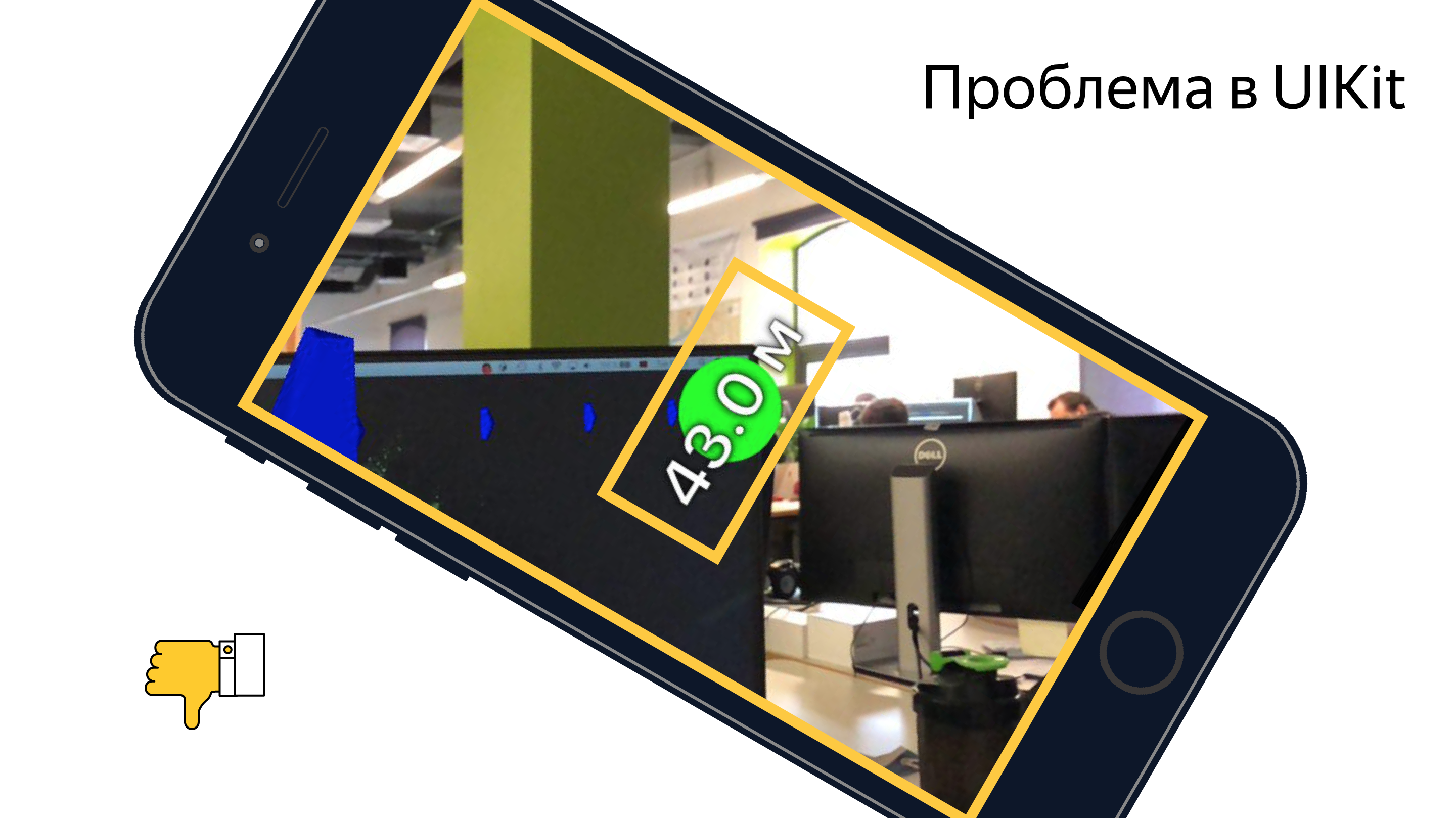
The size
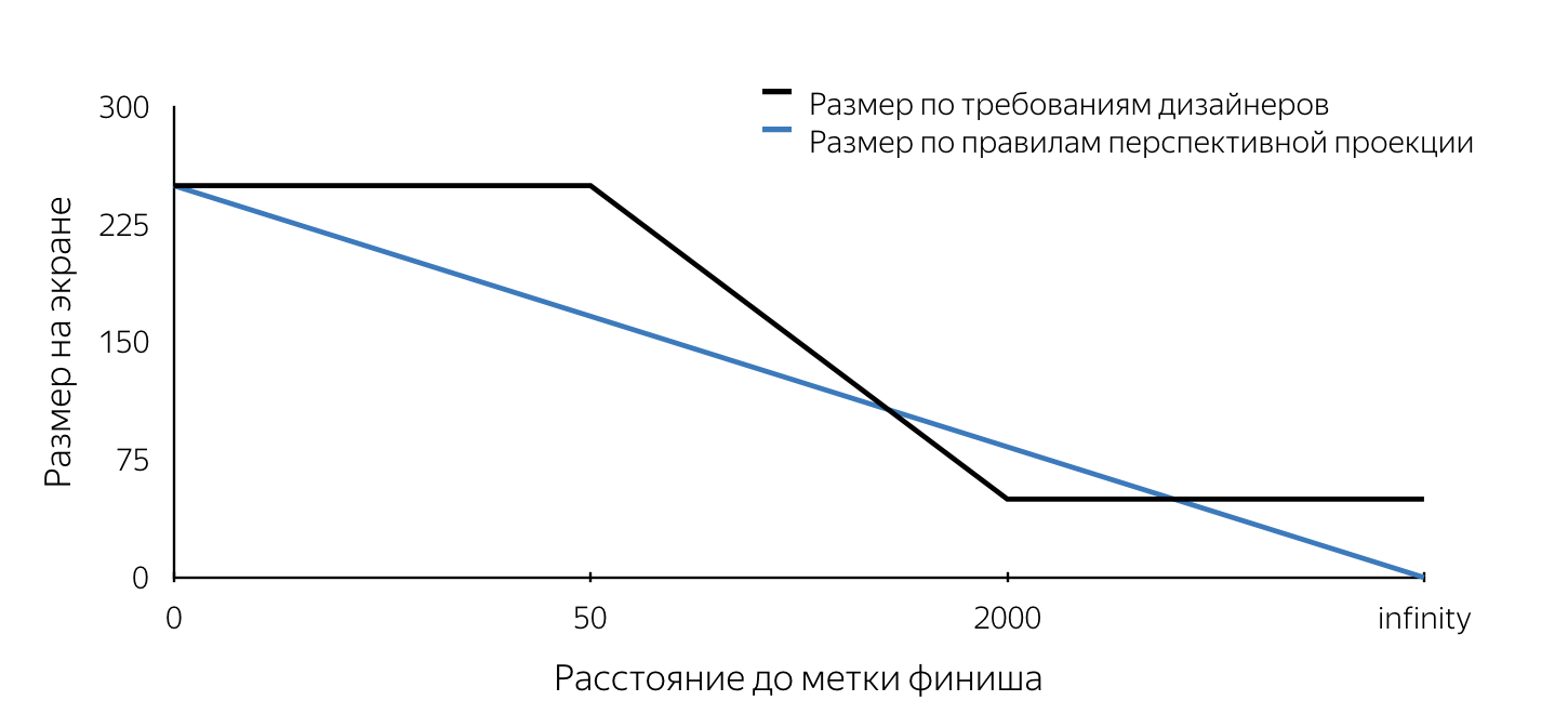
When we were first shown the design of this tag, we first paid attention to the requirements for the size of this tag. They did not obey the rules of perspective projection. Let me explain that in three-dimensional engines that are used to create, for example, computer games, the “look” is modeled using a perspective projection. According to the rules of perspective projection, distant objects are depicted on a smaller scale, and parallel lines in the general case are not parallel. Thus, the size of the projection of an object onto the screen plane changes linearly (decreases) as the camera moves away from the object on the stage. It followed from the description of the layouts that the size of the mark on the screen has a fixed (maximum) size when removed less than 50 m, then decreases linearly from 50 m to 2 km, after which the same minimum size remains. Such requirements are obviously due to user convenience. They allow the user to never lose the end point of the route from view, so the user will always have an idea of where to go.
We had to understand how you can break into the mechanism of projection SceneKit working according to certain rules. I just want to note that we had about two weeks for everything, and therefore there was simply no time to carry out an in-depth analysis of various approaches to solving the set tasks. Now, analyzing our decisions, it is much easier to evaluate them, and it can be concluded that the majority of decisions made were right. The size requirement, in fact, was the first stumbling block. All the problems outlined below can be solved with both SceneKit and UIKit. I tried to describe in detail the ways to solve each of the problems using both approaches. Which approach to use is up to you.
Let's imagine that we decided to implement a finish mark using SceneKit. If we consider that the label on the layouts should look like a circle on the screen, it becomes obvious that in SceneKit the label object must be a sphere (since the projection of the sphere on any plane is a circle). In order for the projection to have a certain radius on the screen, specified in the requirements of the designers, it is necessary to know the radius of the sphere at each moment of time. Thus, placing the sphere of a certain radius on the scene at a certain point and constantly updating its radius when approaching or moving away we will get a projection on the screen of the required size at each moment of time. The algorithm for determining the radius of a sphere at an arbitrary point in time is as follows:
- determine the position of the object on the scene - the center of the sphere,
- find the projection of this point on the screen plane (using the SceneKit API),
- to determine the required size of the label on the screen, we find the distance from the camera to the center of the sphere on the stage,
- determine the required size on the screen according to the distance to the object, using the rules described in the design,
- knowing the size of the label on the screen (the diameter of the circle), choose any point on this circle,
- make a reverse projection (unprojectPoint) of the selected point,
- find the length of the vector from the obtained point on the stage to the center of the sphere.
The resulting value of the length of the vector will be the desired radius of the sphere.

At the time of implementation, we were unable to find a way to determine the size of the object on the stage, and we decided to draw the finish mark using UIKit. The algorithm in this case repeats steps 1-5, after which a circle of the required size is drawn on the screen with its center at the point obtained in step 2 by means of UIKit. An example of the implementation of the label using UIKit can be found here .
At the end of the article, I gave several references to useful and simply interesting materials, including samples, in which you can look at the real code in detail, solve the problems presented in the article and implement the algorithms. The main interest in my opinion is the prototype pedestrian routing , which brings together all the functionality, except for the mechanism for adjusting the axles, which is described in detail below.
The code above does not claim to be optimal, complete and production quality =)
The difference in the use of SceneKit and UIKit in this case lies in the fact that when implemented on SceneKit, the SCNNode object for the end point of the route (finish mark) will be created with the material and geometry, since it must be visible, while using UIKit we will need the node object only to search for a projection on the screen plane (to determine the center of the mark on the screen). Geometry and material in this case do not need to be added. Note that the distance from the camera to the SCNNode object of the end point of the route can be found in two ways - using the geographical coordinates of the points, or as the length of the vector between points on the scene. This is possible due to the fact that the camera object is a property of SCNNode. To get a camera node, you need to refer to the sceneOfView property of our scene.
We learned how to determine the radius of a finish label node at an arbitrary point in time when implemented on a SceneKit and the position of the finish mark view in the case of a UIKit implementation. It remains to understand when it is necessary to update these values? This is the method of the object SCNSceneRendererDelegate:
renderer(_ renderer: SCNSceneRenderer, didRenderScene scene: SCNScene, atTime time: TimeInterval) This method is called after each rendered frame of the scene. By updating the property values in the body of this method, we get the correctly displayed finish mark.
Animation
After the finish mark appeared in dev, we started to add a ripple animation to this mark. I think for most iOS developers, creating animations is not a big deal. But while thinking about the method of implementation, we are faced with the problem of constantly updating the frame of our view. Note that in most cases, animations are added to static UIView objects. A similar problem - a constant update of the radius of a node's geometry also occurs when implemented with SceneKit. The fact is that the pulsating animation is reduced to the animation of the size of the circle (for UIKit) and the radius of the sphere (for SceneKit). Yes, we know that in UIKit such an animation can be done using CALayer, but for the sake of simplicity of the narration I decided to consider this question symmetrically for two frameworks. Consider the implementation on UIKit. If you add a code that animates the same frame to an existing code that updates the frame of the view, the animation will be lost by explicitly setting the frame. Therefore, as a solution to this problem, we decided to use the animation property transform.scale.xy of the UIView object. When implemented using SceneKit, you will have to add an animation of the scale property for the SCNNode object. The nice thing about using SceneKit in this case is the fact that it fully supports CoreAnimation, so learning a new API is not necessary. The code that implements an animation similar to an animation of a label in Yandex.Maps looks like this:
let animationGroup = CAAnimationGroup.init() animationGroup.duration = 1.0 animationGroup.repeatCount = .infinity let opacityAnimation = CABasicAnimation(keyPath: "opacity") opacityAnimation.fromValue = NSNumber(value: 1.0) opacityAnimation.toValue = NSNumber(value: 0.1) let scaleAnimation = CABasicAnimation(keyPath: "scale") scaleAnimation.fromValue = NSValue(scnVector3: SCNVector3(1.0, 1.0, 1.0)) scaleAnimation.toValue = NSValue(scnVector3: SCNVector3(1.2, 1.2, 1.2)) animationGroup.animations = [opacityAnimation, scaleAnimation] finishNode.addAnimation(animationGroup, forKey: "animations") Billboard
At the beginning of the article I mentioned about the billboard with the distance to the end point of the route, which, in fact, is a label with text, located always above the finish line. By tradition, I will identify the problems inherent in the implementations on UIKit and SceneKit, talking about possible solutions for each of the frameworks.
Let's start with UIKit. In this case, the billboard is a regular UILabel, which constantly updates text showing the distance to the end point of the route. Let's look at the problem we are facing.
If you set a label for a frame and then turn the phone, we will see that the frame will not change (it would be strange if this were not the case). At the same time, we would like the label to remain parallel to the ground plane.
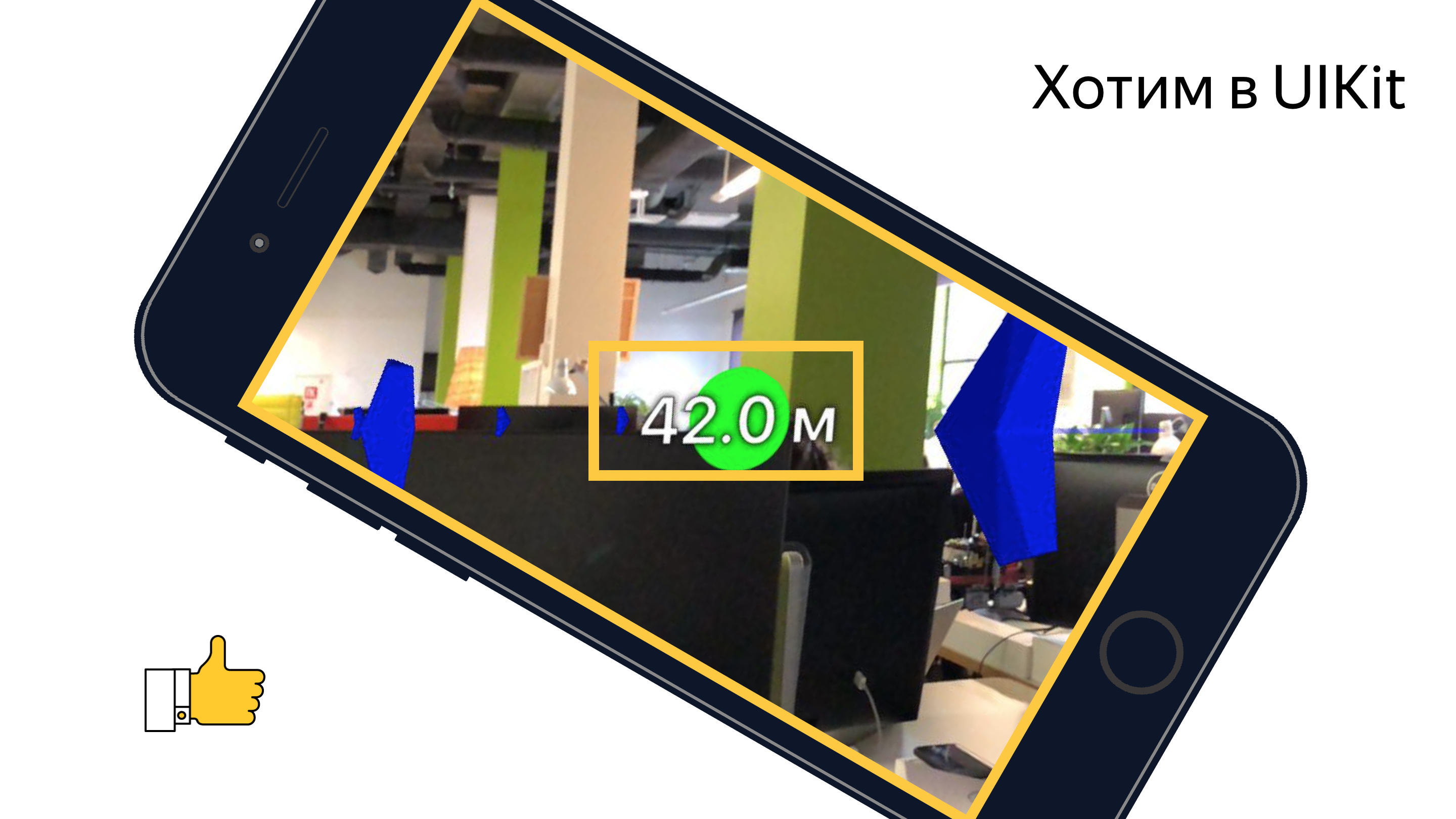
I think everyone understands that when you change the orientation of the device, we need to turn the label, but at what angle? If you turn on the imagination and mentally imagine all the axes of the coordinate systems and vectors involved in this process, you can come to the conclusion that the rotation angle is equal to the angle between the x axis of the UIKit coordinate system and the projection of the X axis of the SceneKit coordinate system onto the screen plane.

A simple task that once again proved the benefits of a school geometry course.
When implementing a finish mark using SceneKit, you will most likely have to render a billboard with a distance using SceneKit means, and this means that you will definitely have a task to force the SCNNode object to always be camera-oriented. I think the problem will become clearer if you look at the picture:

This task is solved by using the SCNBillboardConstraint API. Adding a constraint with a free Y axis to the collection of our node's constraints, we get a node that rotates around the Y axis of its coordinate system so that it is always oriented towards the camera. The sole task of the developer is to place this node at the correct height so that the billboard with the distance is always visible to the user.
let billboardConstraint = SCNBillboardConstraint() billboardConstraint.freeAxes = SCNBillboardAxis.Y finishNode.constraints = [billboardConstraint] Secondary label
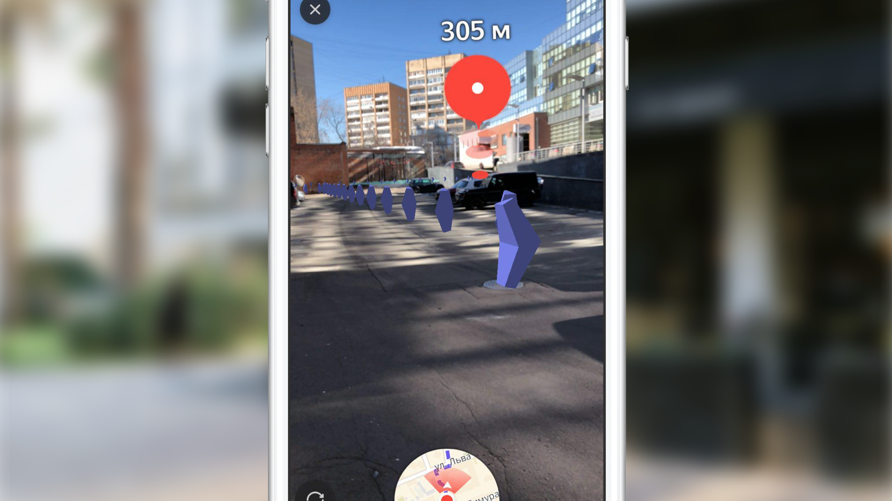
One of the main features of pedestrian routing with augmented reality, we inside the team, consider the auxiliary tag - a special visual element that appears on the screen at the moment when the end point of the route leaves the zone of visibility and shows the user where to turn the phone so that the mark appears on the screen finish line

I'm sure many of the readers have encountered similar functionality in some games, most often - shooters. What was the surprise of our team when we saw this UI element in the layouts. At once I will say that the correct implementation of such a feature may require you more than one hour of experiments, but the end result is worth the time spent. We began by defining requirements, namely:
- With any orientation of the device, the label moves along the edges of the screen,
- if the user has turned 180 degrees to the end point of the route, the label is displayed at the bottom of the screen,
- at each moment of time, turning towards the mark should be the shortest turn to the end point of the route.
After describing the requirements, we started to implement. Almost immediately, we came to the conclusion that rendering would be done using UIKit. The main problem with the implementation was the definition of the center of this label at each point in time. After reviewing the finish mark, such a task should not cause difficulties, so I will not dwell on its solution in detail. In the article I will give only a description of the algorithm for selecting the center of the auxiliary label, and the source code can be found here .
Algorithm for finding the center of the auxiliary tag:
- create an SCNNode object for the end point of the route with a position on the scene obtained from the geographic coordinate of the point,
- find the projection of the point on the screen plane,
- find the intersection of the segment from the center of the screen to the point of the found projection with segments of the screen borders in the coordinate system of the screen.

The found intersection point is the desired center of the auxiliary label. By analogy with the code that updates the parameters of the finish label, we placed the code that draws the auxiliary label in the delegate method already mentioned above.
Route polyline
By constructing a route and seeing the finish mark on the screen, the user can reach it only by looking at the mark, but the routing is called that which shows the route to the user. We thought that it would be very strange to cut down the pedestrian routing functionality by excluding the route display from the AR version. To visualize the route line, it was decided to display a set of arrows moving along it. In this case, the designers were satisfied that the arrows would almost disappear at a distance (the size would be determined by the perspective projection rules), and it was decided to use SceneKit to implement it.
Before proceeding to the description of the implementation, it is important to note that, by design, the arrows should be located at a distance of 3 m from each other. If we estimate the number of objects (arrows) that must be rendered with a route of about 1 km in length, then it will be approximately 330 pieces. At the same time, each object is added animation movement along its route. Note that the arrows removed from the position of the camera on the scene at a distance of about 100-150 meters are almost invisible due to their small size. Having considered these factors, it was decided not to display all the objects, but to display only those that are no more than 100 meters away from the user along the route line, periodically updating the displayed set of objects. We display a sufficient amount of visual information, eliminating unnecessary SceneKit calculations and saving the user's battery.
Let's look at the main steps that we had to implement in order to get the final result:
- selection of the route segment for which we will display primitives,
- creating 3D models
- create animation,
- update while driving on the route.
Select a site to display
As I noted above, we do not display arrows for the entire route, but choose the optimal area for display. Selecting a site at an arbitrary point in time consists in finding the nearest route segment (the route is a sequence of segments / segments) to the current position of the user and selecting segments from the nearest route to the end point until their total length exceeds 100 meters.
Creating a 3D model
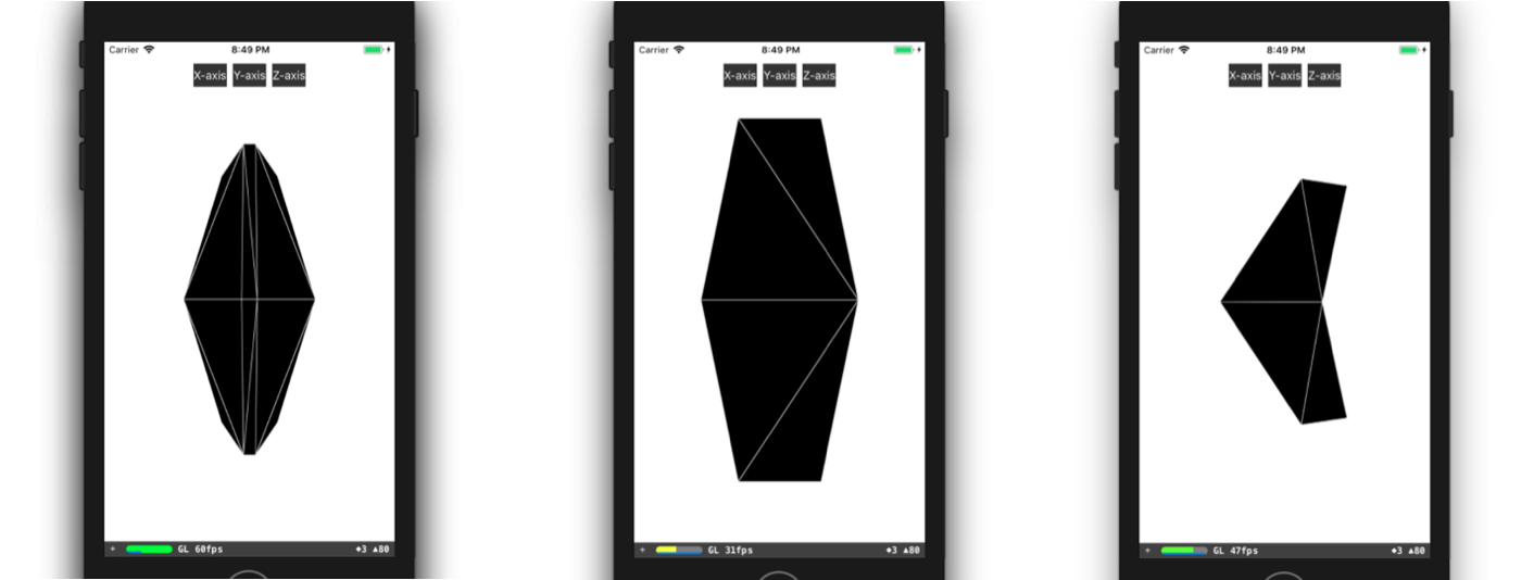
Let us consider in more detail the process of creating a 3D model. In most cases, all you need to do to create a simple 3D model (like our arrow) is to open any 3D editor, spend some time learning it and make this model in it. If the guys from your team have 3D modeling experience, or they have time to learn, for example, 3DMax (and it should be bought), then you are incredibly lucky. Unfortunately, at the time of the implementation of this feature, none of us had any special experience, there was no free time for training, so we had to make a model, so to speak, with improvised means. I mean the description of the model in the code. It all started with the presentation of a 3D model in the form of triangles. Then we had to manually find the coordinates of the vertices of these triangles in the coordinate system of the model, and then create an array of indices of the vertices of the triangles. With this data at our disposal, we can create the necessary geometry directly in SceneKit. You can create a model like ours, for example, like this:
class ARSCNArrowGeometry: SCNGeometry { convenience init(material: SCNMaterial) { let vertices: [SCNVector3] = [ SCNVector3Make(-0.02, 0.00, 0.00), // 0 SCNVector3Make(-0.02, 0.50, -0.33), // 1 SCNVector3Make(-0.10, 0.44, -0.50), // 2 SCNVector3Make(-0.22, 0.00, -0.39), // 3 SCNVector3Make(-0.10, -0.44, -0.50), // 4 SCNVector3Make(-0.02, -0.50, -0.33), // 5 SCNVector3Make( 0.02, 0.00, 0.00), // 6 SCNVector3Make( 0.02, 0.50, -0.33), // 7 SCNVector3Make( 0.10, 0.44, -0.50), // 8 SCNVector3Make( 0.22, 0.00, -0.39), // 9 SCNVector3Make( 0.10, -0.44, -0.50), // 10 SCNVector3Make( 0.02, -0.50, -0.33), // 11 ] let sources: [SCNGeometrySource] = [SCNGeometrySource(vertices: vertices)] let indices: [Int32] = [0,3,5, 3,4,5, 1,2,3, 0,1,3, 10,9,11, 6,11,9, 6,9,7, 9,8,7, 6,5,11, 6,0,5, 6,1,0, 6,7,1, 11,5,4, 11,4,10, 9,4,3, 9,10,4, 9,3,2, 9,2,8, 8,2,1, 8,1,7] let geometryElements = [SCNGeometryElement(indices: indices, primitiveType: .triangles)] self.init(sources: sources, elements: geometryElements) self.materials = [material] } } static func arrowBlue() -> SCNGeometry { let material = SCNMaterial() material.diffuse.contents = UIColor.blue material.lightingModel = .constant return ARSCNArrowGeometry(material: material) } The final result looks like this:
Route line animation
The next step on the way to displaying the animated line of the route was the stage of creating the animation itself. But what is the way to implement the animation, which in its final form looks like the arrow starts its movement at the starting point of the selected section of the route and “floats” along the route to the end of this section?
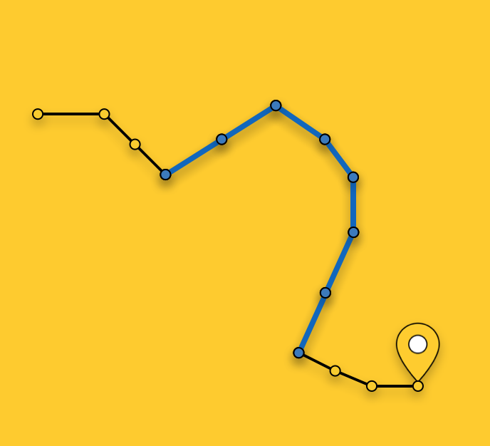
I will not describe all possible ways to create such an animation; instead, I’ll dwell in more detail on the method we have chosen. After the section of the route is selected, we divide it into sections of the same length - sections of the animation of one arrow. Each such area is highlighted in its color and has a length equal to the distance between the arrows.
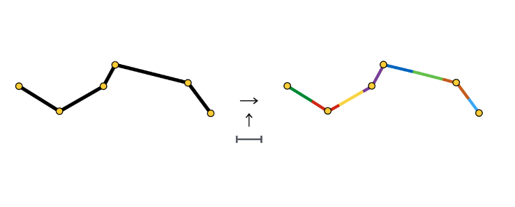
At the beginning of each section, we create an object SCNNode arrows, the animation of which consists in moving along its section.
As you can see, the animation section sometimes consists of one segment, sometimes two or more. It all depends on the step (in our case, 3 meters) between the arrows and the coordinates of the points that make up the route.
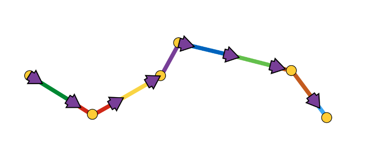
The arrow animation is a sequence of two steps:
- appearance in the initial position with the initial angle of rotation,
- the sequence of displacements along the segments with turns at the junction points of segments
Schematically it looks like this:

It was easiest for us to implement such animation using the SCNAction API, a declarative API that allows you to conveniently create sequential, group, and repetitive animations. More details on the implementation can be here . Due to the fact that each arrow finishes its animation at the starting point of the next arrow’s section of the animation, an impression of continuous arrow movement along the entire selected route’s section appears.
At this point, I propose to finish the consideration of various aspects of rendering and go to the main part - determining the positions of objects on the scene according to the geographical coordinates of the objects.
Determining the position of an object on the stage
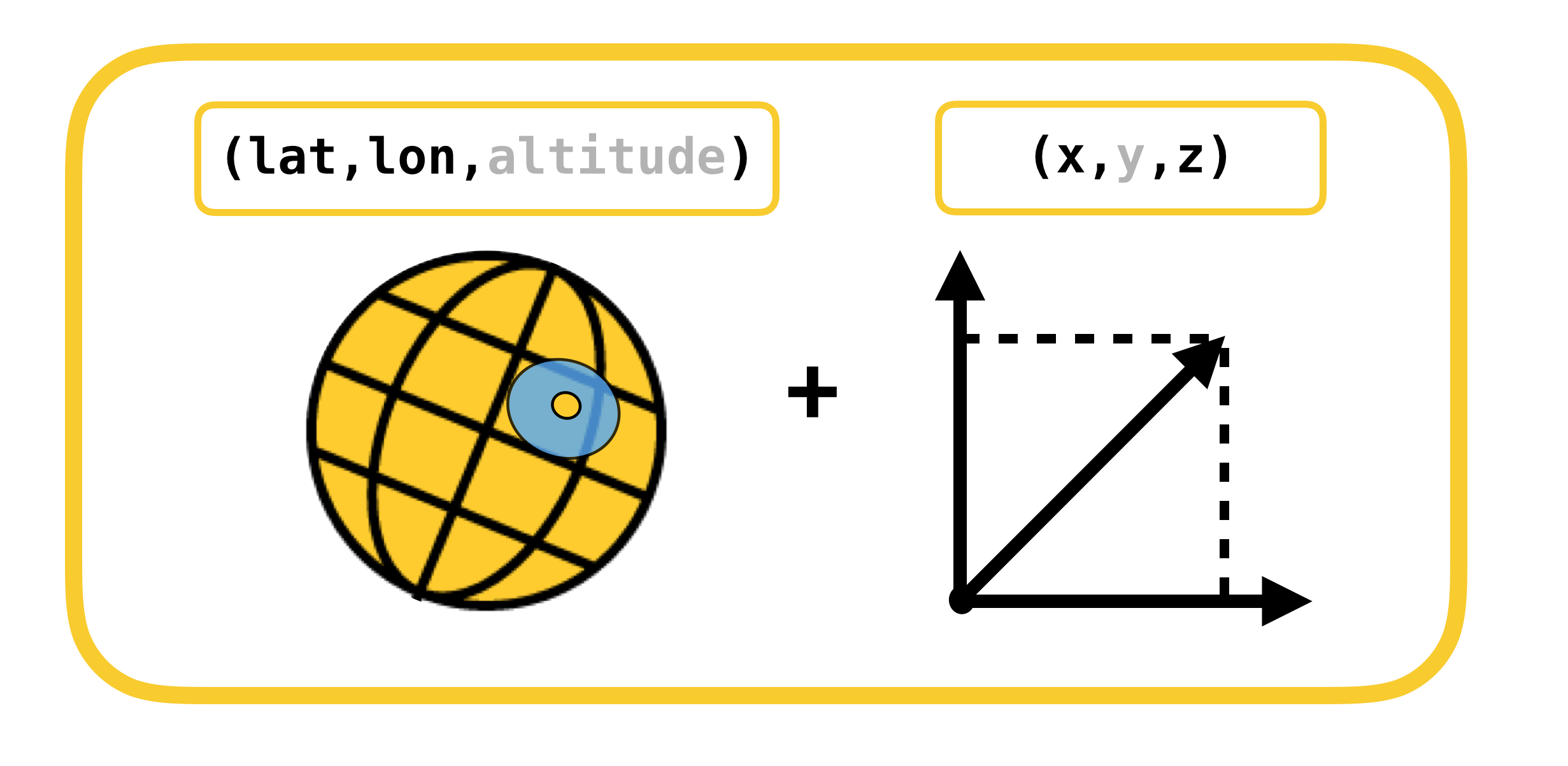
Let's start a conversation about determining the position of an object on the scene with an examination of the coordinate systems, the conversion between which is necessary. There are only 2 of them:
- geodetic (or geographical for simplicity) coordinates - the position of objects (route points) in the real world,
- Cartesian coordinates - the position of objects on the scene (in ARKit). Recall that the scene coordinate system coincides with the ARKit coordinate system (in the case of using ARSCNView).
Translation from one coordinate system to another and vice versa is possible due to the fact that coordinates in ARKit are measured in meters, and the offset between two geodetic coordinates can be translated with great precision into offset in meters along the X and Z axes of the ARKit coordinate system at small offsets. Let me remind you that geodetic coordinates are points with a certain longitude and latitude.
Let us recall such important concepts from the geography course as parallels and meridians, and their basic properties:
- Parallel - line with the degree value of latitude. The lengths of the various parallels are different.
- Meridian - a line with a degree value of longitude. The lengths of all the meridians are the same.
Now let's see how you can calculate the offset in meters, between two geodetic coordinates with coordinates  and
and  :
:
 ,
, 
 ,
, 
Displacement in geodetic coordinates is linearly mapped into meters only at small displacements. At large displacements, you must honestly take the integral.
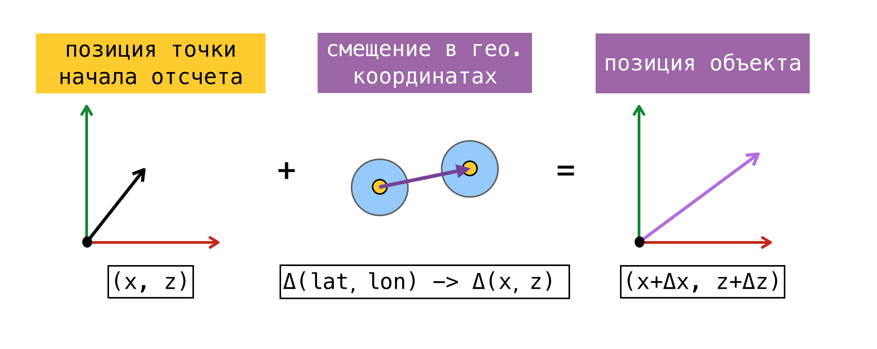
Now, when we are able to translate the offset from one coordinate system to another, we need to determine the point of origin - a point for which the geographical coordinate and coordinate in ARKit (coordinate on the stage) are known at the same time. Having found such a point, we will be able to determine the coordinate of any object on the scene, knowing its geographic coordinate and using the above formulas.
For clarity, consider an example:
At the beginning of the session of augmented reality, we asked CoreLocation our geographic coordinate and received it instantly -  . Recalling the fact that the origin of the ARKit coordinate system is located at the start of the session at the point where the device is located, we obtained the starting point, since we know the geographical coordinate and coordinate on the stage
  . Suppose we need to find a coordinate on the scene of an object with a geographic coordinate . To do this, we find the offset in meters between the geographic coordinate of the object and the geographic coordinate of our point of origin, and then add the found offset to the coordinate on the scene of the point of origin. The resulting coordinate on the stage and will be the desired.
I note that the position found in this way on the scene will correspond to the position of the object in the real world only if the X / Z axis of the coordinate system of the scene is aligned with the directions to the South / East. The alignment of the axes, in theory, should be achieved by setting the worldAlignment flag to gravitiAndHeading. But as I said at the beginning of the post, this is not always the case.
Let us consider in more detail the method of determining the point of reference. To do this, we introduce the concept of estimate - a set of geographic coordinates and coordinates on the stage.
The above proposed method of determining the starting point may not always be used. At the time of the start of the session of the augmented reality, the request for obtaining the user CLLocation may not be executed immediately, moreover, the accuracy of the received coordinate may have a large error. It would be more correct to ask SceneKit for a position on the stage at the moment when we get the value from CoreLocation. In this case, the components of the obtained estimeyta really received simultaneously, and we have the opportunity to use any of the estimeytov, as a starting point. When working with ARKit, the error in bias accumulates over time, so Apple does not recommend using ARKit as a navigation tool.
When we decided to implement pedestrian routing with augmented reality, we conducted a small study of existing solutions using ARKit for similar tasks, and came across the ARKit + CoreLocation framework. The idea behind this framework was that, thanks to ARKit, we can more accurately determine the user's location than using only CoreLocation.
ARKit + CoreLocation concept:
- when receiving CLLocation from CLLocationManager
- request position on stage using scene.pointOfView.worldPosition
- save this pair of coordinates (estimate) to the buffer
- get exact location if necessary
- we choose the best estimate
- calculate the offset between the current position on the stage and the position on the stage of the best estimeyta
- apply the found offset to the geographic coordinate of the best estimate
, , CoreLocation, .
, « ». , .
(, ):
- ( horizontalAccuracy),
- ,
- 100 .
CoreLocation . , , CoreLocation , 100 .
, . , , ( 100 ).
, X/Z ARKit / . ARKit , , .
, (, IKEA, ), Y ARKit – , . gravity worldAlignment.
, . , , , . . AR . , , , , . AR.
, . ,  CLLocationManager —
  .
.  CLLocationManager —
  respectively.
ARKit —  2 CoreLocation .
  . , CoreLocation . . ARKit /.
ARKit Y? . :
- ,
- ,
- ,
- ,
- .
. . CLLocationManager' , ( ), ( ).
. , , . , , GPS .
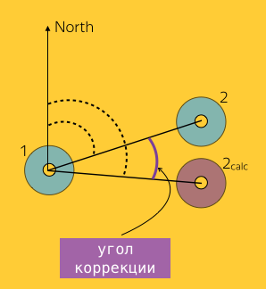
1, 2 :  and
and  where
where  – 2, ARKit.
  ( Bearing).
. , ? , , , , . , , , horizontalAccuracy. , , , . :
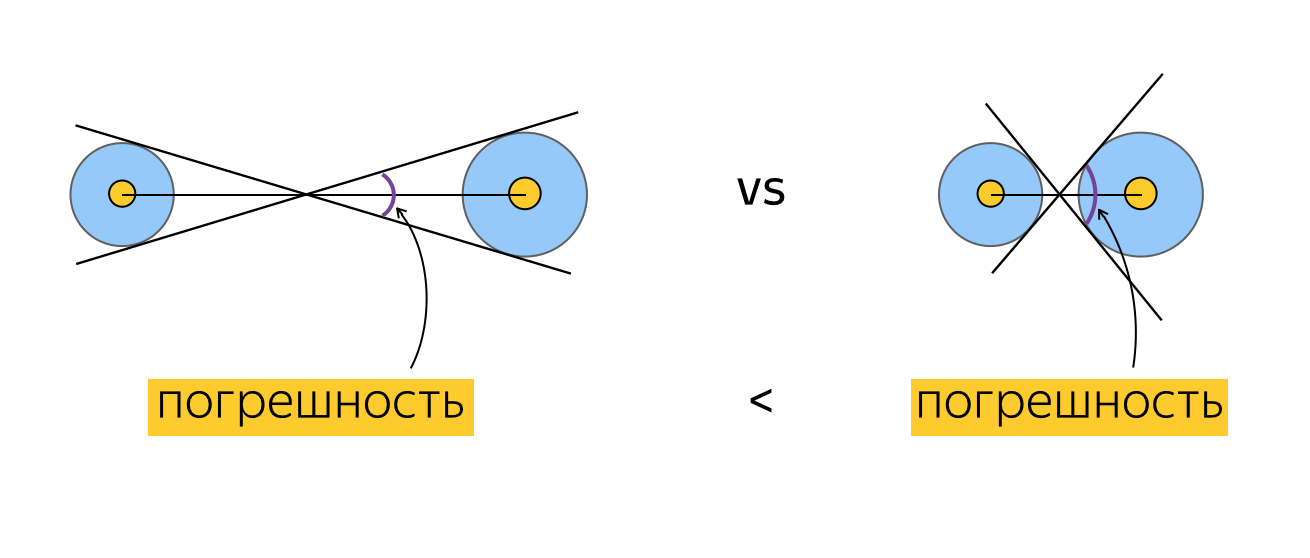
, , .
. , . For example:
- N ,
- ,
- M ( ?).
, , , , (), . , . , , . , , ( ). .
, . , , ( , , ).
Testing
, . , , , . 2 :
- ,
- .
- , , , , .
. , , 100 CLLocation, . , , , 10 ( 10 ). ? , "". , . , , , . , , . , CoreLocation. , . , .
. , . , (, ), , 0 . , , .
" ". . , , , , CLLocation, , . ( ) .
, ARKit.

, .

( 3-4 ) , .
JS, AR CoreLocation.

— gravity worldAlignment . , . .
Instead of conclusion
Slack, , , , . AR. . AR AppStore 2017 . , .
useful links
, . .
')
Source: https://habr.com/ru/post/421957/
All Articles