Parktronic on Arduino
In this publication we will talk about creating a simple parking sensors based on Arduino.
A bit of theory. Parktronic or Parking radar is a device designed to track the distance between a car and an object, as a rule, parktronics are installed from the back of the car.
Even despite the price of ~ 1936 rubles, I decided to make my own version of this device. I decided to start small, and probably created the simplest parking sensors out of all possible.
And so from theory to practice, to build the device we need, 3 LEDs (I took different colors, it's easier and clearer); Piezo generator with generator *; Ultrasonic Range Finder HC-SR04; A resistor of 220 ohms and a power of 0.25 watts (although others are appropriate, there is no need for more power) and any model Arduino.
')
Assembly.
Well, the scheme we have collected, what next? And then we write the program, for those who do not know Arduino is programmed in YaP Wiring, this is a simplified C ++, the easiest way to use Arduino IDE as IDE.
Here is the program:
I did not assemble the finished device because now I am working on a new PON-2 model with a four-digit seven-segment indicator.
Some photos, videos, and pictures:
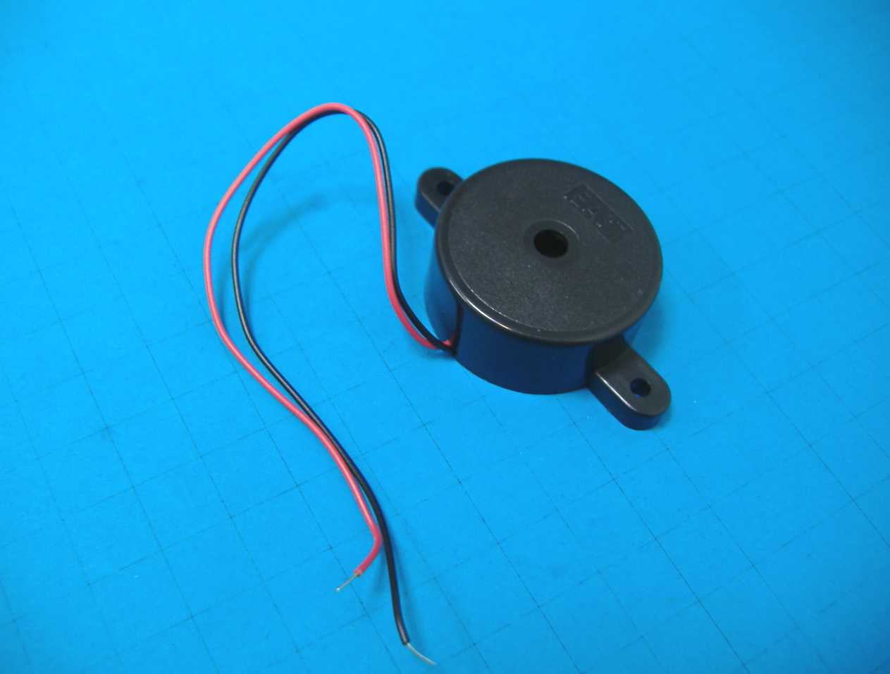
* A piezo transmitter with a generator looks like this:
Step 1:
Step 2:

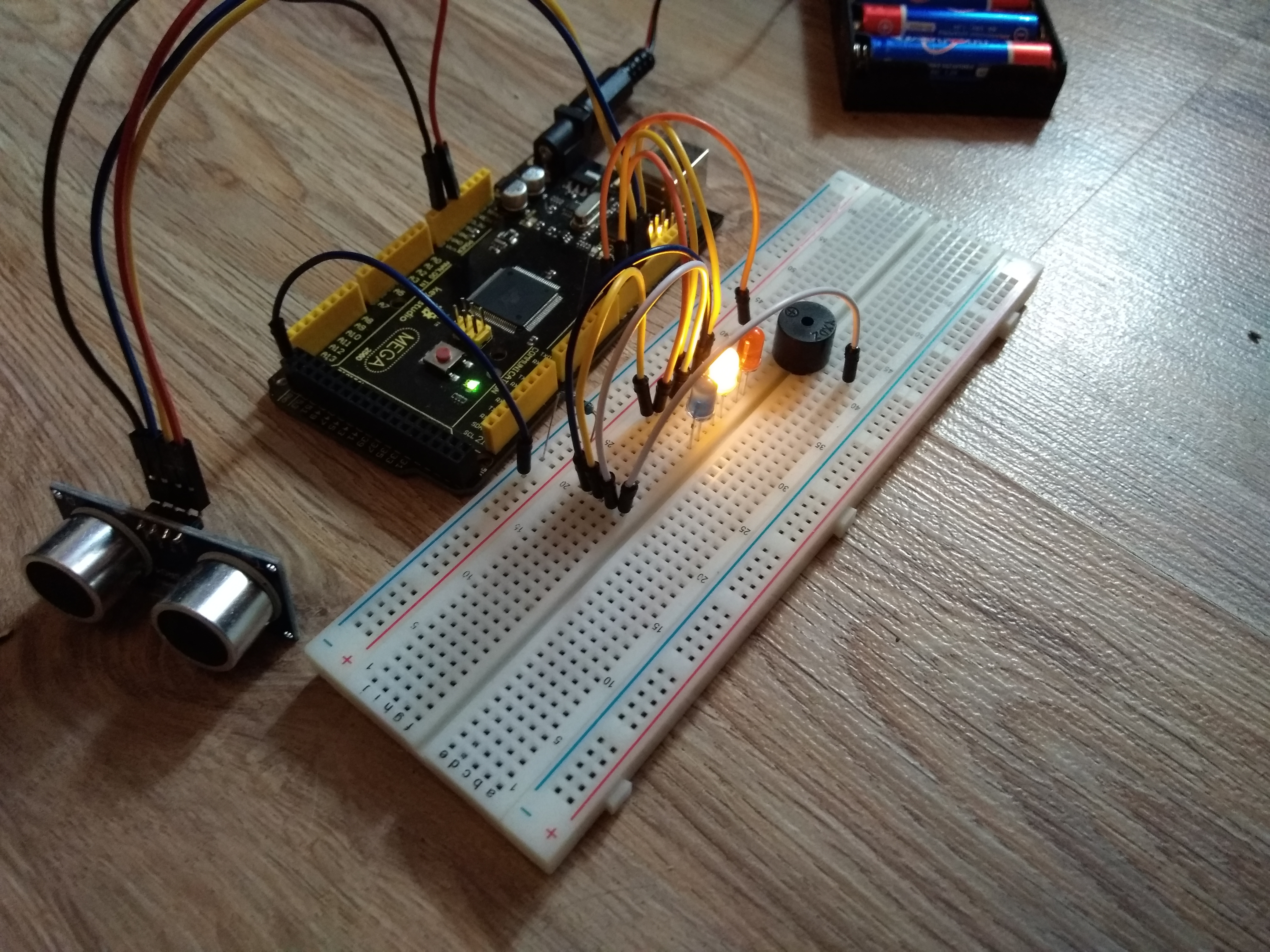
Device operation in pictures:


A piece of program code and information about the range finder HC-SR04 I got from this site
A bit of theory. Parktronic or Parking radar is a device designed to track the distance between a car and an object, as a rule, parktronics are installed from the back of the car.
Even despite the price of ~ 1936 rubles, I decided to make my own version of this device. I decided to start small, and probably created the simplest parking sensors out of all possible.
And so from theory to practice, to build the device we need, 3 LEDs (I took different colors, it's easier and clearer); Piezo generator with generator *; Ultrasonic Range Finder HC-SR04; A resistor of 220 ohms and a power of 0.25 watts (although others are appropriate, there is no need for more power) and any model Arduino.
')
Assembly.
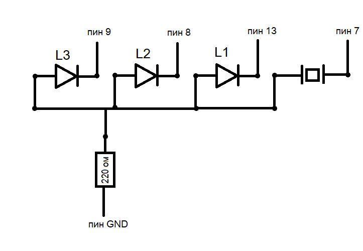
- GND (-) LEDs and a piezo emitter are connected together and connected to the GND pin via a resistor.
- VCC (+) at the range finder we connect with pin + 5V Arduino, Trig at 10, Echo at 11, and where GND think already is clear.
Well, the scheme we have collected, what next? And then we write the program, for those who do not know Arduino is programmed in YaP Wiring, this is a simplified C ++, the easiest way to use Arduino IDE as IDE.
Here is the program:
int trigPin = 10; // Trig int echoPin = 11; // Echo int rLed = 12; // LED int yLed = 8; // LED int bLed = 9; // LED int buzz = 7; // void setup() { // pinMode(trigPin, OUTPUT); pinMode(echoPin, INPUT); pinMode(bLed, OUTPUT); pinMode(yLed, OUTPUT); pinMode(rLed, OUTPUT); pinMode(buzz, OUTPUT); } void loop() { int duration, distance; // LOW Trig digitalWrite(trigPin, LOW); delayMicroseconds(2); // Trig digitalWrite(trigPin, HIGH); // 10 μs delayMicroseconds(10); digitalWrite(trigPin, LOW); // Echo duration = pulseIn(echoPin, HIGH); // distance = duration / 58; if (distance > 20) { // > 20 digitalWrite(bLed, HIGH); // LED digitalWrite(yLed, LOW); digitalWrite(rLed, LOW); digitalWrite(buzz, LOW); } else if (distance <= 20 && distance > 10) { // // 20 10 digitalWrite(yLed, HIGH); // LED digitalWrite(bLed, LOW); digitalWrite(rLed, LOW); digitalWrite(buzz, LOW); } else if (distance < 10) { // < 10 digitalWrite(rLed, HIGH); // LED digitalWrite(yLed, LOW); digitalWrite(bLed, LOW); digitalWrite(buzz, HIGH); // } delay(100); // 100 } I did not assemble the finished device because now I am working on a new PON-2 model with a four-digit seven-segment indicator.
Some photos, videos, and pictures:
* A piezo transmitter with a generator looks like this:
Step 1:
Step 2:
Device operation in pictures:
A piece of program code and information about the range finder HC-SR04 I got from this site
Source: https://habr.com/ru/post/421747/
All Articles