To the question of the impossible. Part 3
Zero rule engineer "Wonders in the world does not happen"

"And the killer - the postman"
We continue the notes of Sherlock Oms, and, as always, consider the cases of the impossible functioning of electronic devices. Under the cut will be a session of black magic with exposure.
The first case - a young colleague turned to me for help (if you are reading this, Andrew, thanks for the tip-off), who was seriously puzzled by the behavior of the device he designed. In addition to everything else, the device had voltage dividers, the signal from which through the low-pass filter (50 kΩ resistor and 0.2 μf capacitor) was fed to the inputs of the microcontroller's ADC - see the diagram in Figure 1.
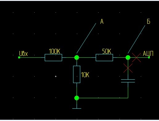
And here in this simple circuit a mystery was revealed - a voltage of 3V was measured at the divider (point A), and 2.5V at the input of the ADC (point B), and the input resistance of the MC could not lead to a similar result. We reflect on possible causes and experiment, because the engineer differs from an ordinary person in that he “thinks with his hands”.
Version 1) At one time I had a similar defect caused by the presence of non-disconnected pull-up resistors on the MK legs, but a simple check - tearing the MK foot off the circuit (the red cross in the diagram) showed that the microcontroller had nothing to do with it.
')
Version 2) A leak through the filter capacitor - well, maybe a defective batch of condenders got caught - we remove the condenser (the second red cross), and it does not help.
Version 3) Leakage on the board - we do not seriously consider it, since I cannot believe in a leakage with a nominal value of 2.5 / 0.5 * 50 = 250 kOhm, it must be a wildly dirty card, just in case washed with alcohol - it did not help.
Version 4) Interference, for example, a tip from the network - “of course, we have a shortage of boys, but not to the same degree” - 0.5 V per 50k - this is not an interruption, but interferences (not sure if you can write this, but I will try) . Nevertheless, we are looking at an oscilloscope with a 200 MHz band and we see a net constant, so there is no interference (or rather, there is no interference in the range up to 100 MHz, but I believe in less gigabyte-hertz interference, there is no radar near).
There is a shortage of further ideas - a measurement error is possible (that is, poking the wrong way) - I take the probes in hand and begin to measure it myself (until that time my young colleague was involved, I looked at the instrument panel). And it turned out - I intended on both sides of a 3V resistor (well, more correctly, 3 and 2.9, but this is the same thing). But, when I give the probes and we change places again, the effect returns, despite the fact that the measurement points remain the same and, this time, definitely correct. Moreover, now sometimes, when measuring on the divider, we see 2.5V, and at the entrance of the MK 3B, which does not fit into any gate at all.
In principle, there is enough information to determine the cause of the phenomenon, we proceed to the next task.
The second funny situation is that they bring us one product for repair, in which the LED has stopped turning on (Diagram 2).
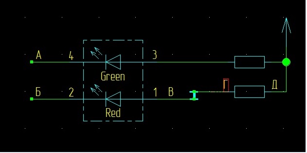
Red works, no green - it happened with us, they changed these details and there were signs of an obvious counterfeit, but here the product worked before.
Without thinking twice, we connect the test equipment, send an excitation signal to the red minus (for many years of work, I never remembered who the cathode was, and who was the anode, and for the lamps there was a wonderful rhyme "our hot cathode ...", but for semiconductors I I do not know this), we measure it with the device at point A, initially we see 1.5V, when 0 is excited (I will not indicate further volts) - everything is fine.
To control, we give a signal for a green minus and look at point B, initially we see 1.5, at excitation 0, the signal comes, probably, after all the LED. Nevertheless, it is necessary to examine the plus of the diode (of course, the resistors do not burn out, but you never know), so we measure at point B and find -6. As it is strange, considering that the board is served only power 3.3.
We turn over the board and measure it on a resistor (points D and D) - at both ends of 3.3, so the resistor is OK, which means that the LED is still faulty, but then we notice that it lights up.
The defect is trivial - not a resistor, but what a strange negative voltage - with an unwavering hand we take down the resistor in general (we can still re-solder), we turn the board over - we measure at point B and again we see -6. We turn the board over again and measure it at the point G - 0 (this is not zero in the sense of zero potential), as expected. That is, a generator of a weak negative voltage sits in the transition hole - “well, do not eat a dumpling”, it does not happen, did you really start to make bookmarks in printed circuit boards. Again, I take away the young colleague (this time of the other, nothing, that I mention you here, Danil?) Probes and I poke myself to point G and see -4, which is somewhat better, but still mysterious.
Again there is enough information to understand what is happening, those who still have little of it, can press a button.
And here is the exposition of magic, as always, natural science, “I am a materialist” (Count Cagliostro as amended by Gorin).
In both cases, we are dealing with the Pauli principle about the influence of the fact of measurement on the measured parameter. It was believed that it manifests itself only in the micro-world, but we were able to observe it at the macro level. This, of course, is an unsuccessful joke, but the point is in the meter, because in measurements, besides the device, a person also participated (we will call it further a meter).
The fact is that the first payment was paid for and the probe shown on the CCDT was used to access the points. Usually, a person holds a measuring probe for an insulating cover and does not affect the circuit under study, but it is extremely difficult to isolate from the probe if you don’t wear gloves. Yes, I know that there are areas of electrical engineering, where they are immediately denied admission for such behavior (and they do it right), but we are weak-tempered (the term “short-term employees” somehow didn’t take it, although it better reflects the essence of the distinction) and allow ourselves a lot.
By the way, about weakness - when I was young, I had in one product capacitors (electrolytic, of course, K50-18) with a capacity of 100 thousand microfarads at 6.3 (those who saw, remember, others can see pictures on the Web to evaluate scale of disaster). So, we had entertainment - to charge it, and then put a screwdriver on the terminals and watch how a piece of millimeter metal is gnawed out of it for 3. And an interesting behavior was observed - we understood perfectly well that the voltage is absolutely safe, but still after receiving the sheaf sparks touched the terminals of the capacitor with obvious caution - the mind claims one thing, but instincts say that everything is not so simple and this thing cannot be safe.
We return to our measurements and conclude that in the first circuit we need to add one more element - a meter, the equivalent circuit of which for this case will be represented by a resistor (circuit 1a).
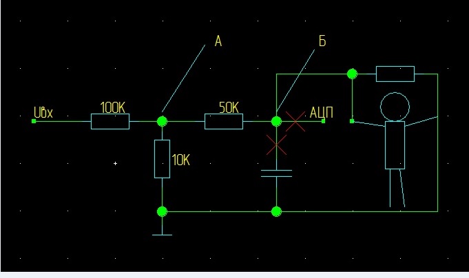
Then for a young colleague, you can calculate the resistance and it will be 250k - I ask him to take a probe in each hand and we really see this figure. For me, the corresponding resistance should be 2m, which was brilliantly confirmed by the experiment. The scheme, which is designed by a colleague, is completely working and functions well, just should not be grabbed with bare hands for anything.
With the second case, it is more interesting and our equivalent observer circuit cannot answer why the supply voltage not only decreased, but also pro-inverted. We will have to attract an extended model, where the spherical meter is not in a vacuum, but in a real environment, which is characterized by the presence of electromagnetic waves, primarily related to the mains voltage. Then you can consider it as an equivalent signal source (Figure 2a):
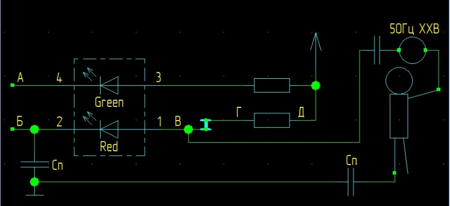
And indeed, if you take an oscilloscope probe in your hand, then this signal can be observed. Its frequency will be 50 Hz, the form will be very far from sinusoidal (by the way, and why it is far - I suppose that due to the reactivity of consumption, but I could be wrong), the amplitude varies greatly from meter to meter.
However, if we take an instrument probe in hand, we do not observe voltage (in the constant voltage measurement mode), since the average value of the induced signal is zero, and the voltage on the board is negative. This fact is perfectly explained by the presence of a healthy diode at the connection point. The diode suppresses a positive half-wave of the signal with an amplitude of more than 1.5 on itself and an average negative value arises, which is indicated by the device. Since the board is not paid, there is no need to resort to the services of the probe, so on the back of the board just look at the probe and there we have the expected 0, and there is mastic on the legs of the diode, so we use the probe and get what we get - induced voltage with negative average, whose value depends on the specific meter, in particular, the state of its skin (probably, also from many other factors, but we will not focus on this, it is rather a subject of biology, not electronics).
"Speaking of birds," when I wrote about 0, I did not mean the potential of the earth, but only the absence of any significant voltage on the dipstick, that is, an open circuit. As much as I am in the profession, I dream so much about a device that will show the real zero and the absence of a signal in different ways. If among the readers of this post there are manufacturers of compact measuring devices (which is unlikely, since I am not writing in Chinese), consider this paragraph as a technical task that also applies to oscilloscope probes. It seems to me that this function can be quite realized (and not expensive, however, and what our southern colleagues do expensively?) At the modern level of electronics development, but, probably, I don’t know something.
These are two funny stories united by the main character - a measuring probe in combination with a meter, which should remind the reader to take into account all the factors affecting the circuit in the measurement process.
Source: https://habr.com/ru/post/421357/
All Articles