Semi-passive cooling of computer power supply unit
Hello! This device is applicable not only in a computer power supply unit, but we will be pro computer, as urgent :)
The process technology of production of processors steadily decreases, along with it decreases and power consumption. Processors of the latest generations contain graphic video system suitable for everyday tasks. If you are not very demanding of performance in video games, then for a relatively modest budget, you can think about a quiet computer that will make sounds only under heavy load, which does not happen often.
Next comes my vision of a computer configuration for semi-passive cooling.
')
The average CPU at the peak of its load emits 65 W of heat, it can be cooled by a factory cooler with a greater (than regular) capacity of 120-150 W by setting the BIOS settings so that it starts spinning only when the CPU is loaded with 30-40% CPU or above 40 ° C.
Another source of noise is HDD, but everything is simple, I replaced it with an SSD.
There is a power supply fan that runs constantly. You can buy a completely passive or semi-passive initially, but here the price of the question: (from $ 150) maybe it makes sense to send these funds for greater performance?
A normal, 500 W power supply ($ 50) has a huge power margin in my case, so I decided to turn off the fan completely. But during long-term operation under heavy load, the radiators inside the steel began to heat up above 60 ° C, so it was decided to return the fan but to make its turns controlled.
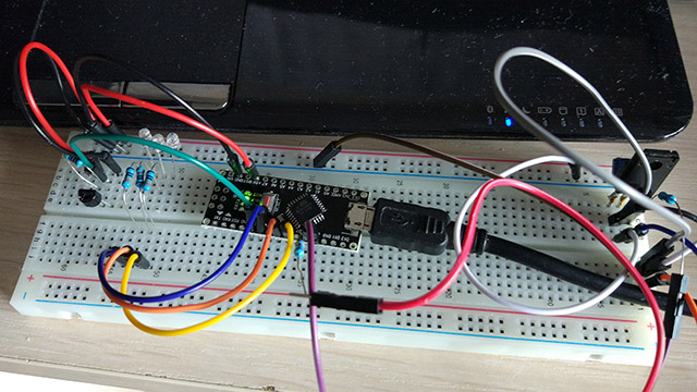
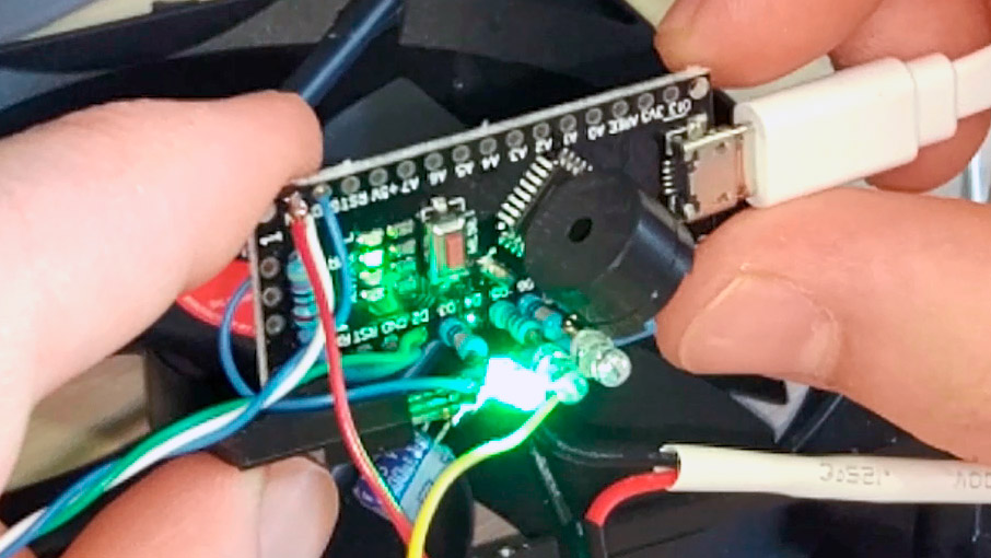
The basis was taken Arduino nano on the basis of ATMEGA168PA, from different pieces of other people's projects made its own.
Since the resources of the controller allow, it was decided to make a three-color LED indicator of a smart LED type with different blinking and color depending on the temperature.

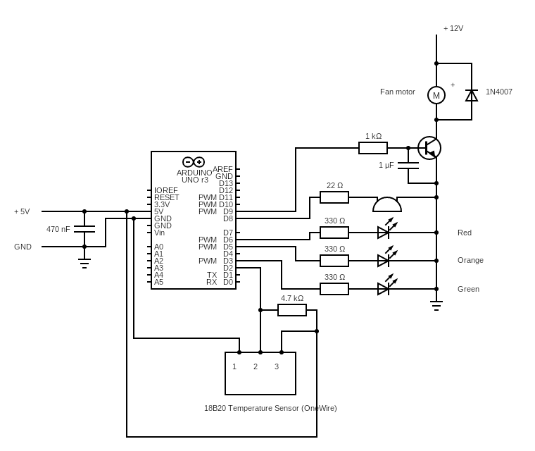
The temperature is measured by the DS18B20 sensor, and the fan speed increases or decreases depending on the temperature. When reaching> 67 ° C, an audio detector is activated. Transistor - any NPN with a current> current of your fan. I also tried to control a three-wire fan, everything turned out, but I could not make it stop completely.
Initially, I used the default PWM frequency (448.28 Hz), but at low revs the cooler made a barely perceptible ring that doesn’t fit in with the concept of silent cooling. Therefore, the software frequency PWM raised to 25 kHz. At the lowest revs, the fan cannot immediately start, therefore, for the first two seconds, it is given an impulse with maximum revolutions, further revs according to the program.
Here is a video demonstrating the operation of the device.
But actually, the sketch, please do not kick it very much, this is my first sketch for Arduina :)
The process technology of production of processors steadily decreases, along with it decreases and power consumption. Processors of the latest generations contain graphic video system suitable for everyday tasks. If you are not very demanding of performance in video games, then for a relatively modest budget, you can think about a quiet computer that will make sounds only under heavy load, which does not happen often.
Next comes my vision of a computer configuration for semi-passive cooling.
')
The average CPU at the peak of its load emits 65 W of heat, it can be cooled by a factory cooler with a greater (than regular) capacity of 120-150 W by setting the BIOS settings so that it starts spinning only when the CPU is loaded with 30-40% CPU or above 40 ° C.
Another source of noise is HDD, but everything is simple, I replaced it with an SSD.
There is a power supply fan that runs constantly. You can buy a completely passive or semi-passive initially, but here the price of the question: (from $ 150) maybe it makes sense to send these funds for greater performance?
A normal, 500 W power supply ($ 50) has a huge power margin in my case, so I decided to turn off the fan completely. But during long-term operation under heavy load, the radiators inside the steel began to heat up above 60 ° C, so it was decided to return the fan but to make its turns controlled.
Different power supplies have different design features, perhaps in some cases, constant airflow is necessary. Therefore, before making changes to the design of your BP, realize that you understand the process, you have sufficient “even hands” and that the changes made will not adversely affect the operation of your BP and related equipment. It often happens that the power supply unit pumps the air of the entire system unit. Any modifications may damage your computer!
The basis was taken Arduino nano on the basis of ATMEGA168PA, from different pieces of other people's projects made its own.
Since the resources of the controller allow, it was decided to make a three-color LED indicator of a smart LED type with different blinking and color depending on the temperature.
The temperature is measured by the DS18B20 sensor, and the fan speed increases or decreases depending on the temperature. When reaching> 67 ° C, an audio detector is activated. Transistor - any NPN with a current> current of your fan. I also tried to control a three-wire fan, everything turned out, but I could not make it stop completely.
Initially, I used the default PWM frequency (448.28 Hz), but at low revs the cooler made a barely perceptible ring that doesn’t fit in with the concept of silent cooling. Therefore, the software frequency PWM raised to 25 kHz. At the lowest revs, the fan cannot immediately start, therefore, for the first two seconds, it is given an impulse with maximum revolutions, further revs according to the program.
Here is a video demonstrating the operation of the device.
But actually, the sketch, please do not kick it very much, this is my first sketch for Arduina :)
Click to view code
// 2 - DS18x20 data // 3 - green LED (a 330 Ohm resistor is necessary) // 5 - orange LED (a 330 Ohm resistor is necessary) // 6 - red LED (a 330 Ohm resistor is necessary) // 9 - PWM Fan // 8 - Buzzer #include <OneWire.h> byte temp; // temperature of sensor byte greenLED = 3; byte orangeLED = 5; byte redLED = 6; byte FanSpeed = 0; int piezoPin = 8; // byte modes[] = { 0B00000001, // 0B00000101, // 0B00010101, // 0.5 0B01010101, // 0B10101010, // 0B00010101, // 0B01010101 // (4 ) }; uint32_t ms, ms1 = 0, ms2 = 0, ms3 = 0, ms4 = 0, ms5 = 0; uint8_t blink_loop = 0; uint8_t blink_mode = 0; uint8_t modes_count = 0; bool FirstRun = 0; OneWire ds(2); // on pin 10 (a 4.7K resistor is necessary) void analogWrite25k(int pin, int value) { switch (pin) { case 9: OCR1A = value; break; case 10: OCR1B = value; break; default: // no other pin will work break; } } void setup(void) { pinMode(redLED, OUTPUT); pinMode(greenLED, OUTPUT); pinMode(orangeLED, OUTPUT); pinMode(9, OUTPUT); modes_count = 1; blink_mode = modes[modes_count]; TCCR1A = 0; // undo the configuration done by... TCCR1B = 0; // ...the Arduino core library TCNT1 = 0; // reset timer TCCR1A = _BV(COM1A1) // non-inverted PWM on ch. A | _BV(COM1B1) // same on ch; B | _BV(WGM11); // mode 10: ph. correct PWM, TOP = ICR1 TCCR1B = _BV(WGM13) // ditto | _BV(CS10); // prescaler = 1 ICR1 = 200; // TOP = 320 // Serial.begin(9600); } void loop() { byte i; byte present = 0; byte type_s; byte data[12]; byte addr[8]; float celsius; if ( ( ms - ms3 ) > 1000 || ms < ms3 ){ ms3 = ms; if ( !ds.search(addr)) { // Serial.println("No more addresses."); // Serial.println(); ds.reset_search(); if ( ( ms - ms4 ) > 250 || ms < ms4 ){ ms4 = ms; //delay(250); return; } } // Serial.print("ROM ="); for( i = 0; i < 8; i++) { // Serial.write(' '); // Serial.print(addr[i], HEX); } if (OneWire::crc8(addr, 7) != addr[7]) { // Serial.println("CRC is not valid!"); return; } // Serial.println(); // the first ROM byte indicates which chip switch (addr[0]) { case 0x10: Serial.println(" Chip = DS18S20"); // or old DS1820 type_s = 1; break; case 0x28: Serial.println(" Chip = DS18B20"); type_s = 0; break; case 0x22: Serial.println(" Chip = DS1822"); type_s = 0; break; default: Serial.println("Device is not a DS18x20 family device."); return; } ds.reset(); ds.select(addr); ds.write(0x44, 1); // start conversion, with parasite power on at the end } //delay(1000); // maybe 750ms is enough, maybe not // we might do a ds.depower() here, but the reset will take care of it. if ( ( ms - ms2 ) > 900 || ms < ms2 ){ ms2 = ms; present = ds.reset(); ds.select(addr); ds.write(0xBE); // Read Scratchpad for ( i = 0; i < 9; i++) { // we need 9 bytes data[i] = ds.read(); } // Convert the data to actual temperature // because the result is a 16 bit signed integer, it should // be stored to an "int16_t" type, which is always 16 bits // even when compiled on a 32 bit processor. int16_t raw = (data[1] << 8) | data[0]; if (type_s) { raw = raw << 3; // 9 bit resolution default if (data[7] == 0x10) { // "count remain" gives full 12 bit resolution raw = (raw & 0xFFF0) + 12 - data[6]; } } else { byte cfg = (data[4] & 0x60); // at lower res, the low bits are undefined, so let's zero them if (cfg == 0x00) raw = raw & ~7; // 9 bit resolution, 93.75 ms else if (cfg == 0x20) raw = raw & ~3; // 10 bit res, 187.5 ms else if (cfg == 0x40) raw = raw & ~1; // 11 bit res, 375 ms //// default is 12 bit resolution, 750 ms conversion time } celsius = (float)raw / 16.0; temp = celsius; // Serial.println("TEMPERATURE IS:"); // Serial.println(temp); } ms = millis(); // 125 if( ( ms - ms1 ) > 125|| ms < ms1 ){ ms1 = ms; // if ( temp <= 50 ) { digitalWrite(orangeLED, LOW); digitalWrite(redLED, LOW); if( blink_mode & 1<<(blink_loop&0x07) ) digitalWrite(greenLED, HIGH); else digitalWrite(greenLED, LOW); blink_loop++; if ( temp <= 40 ) { blink_mode = modes[0]; analogWrite25k ( 9, 0); FirstRun = 0; } if ( temp >= 41 && temp <= 45 ) { blink_mode = modes[1]; // Make a push impulse for starting fan (1 sec) if ( FirstRun == 0 ) { ms5 = ms; FirstRun = 1; } if (FirstRun == 1 && (2000 > (ms - ms5))) { analogWrite25k ( 9, 33); // Fan start impulse } if (FirstRun == 1 && (2000 < (ms - ms5))) { analogWrite25k ( 9, 28); // first speed } } if ( temp >= 46 && temp <= 50 && FirstRun == 1) { blink_mode = modes[2]; analogWrite25k ( 9, 29); } } if ( temp >= 51 && temp <= 61 ) { digitalWrite(greenLED, LOW); digitalWrite(redLED, LOW); if( blink_mode & 1<<(blink_loop&0x07) ) digitalWrite(orangeLED, HIGH); else digitalWrite(orangeLED, LOW); blink_loop++; if ( temp >= 51 && temp <= 54 ) { blink_mode = modes[0]; analogWrite25k ( 9, 30); } else if ( temp >= 55 && temp <= 58 ) { blink_mode = modes[1]; analogWrite25k ( 9, 31); } else if ( temp >= 59 && temp <= 61) { blink_mode = modes[2]; analogWrite25k ( 9, 32); } } if ( temp >= 62 && temp <= 120 ) { digitalWrite(greenLED, LOW); digitalWrite(orangeLED, LOW); if( blink_mode & 1<<(blink_loop&0x07) ) digitalWrite(redLED, HIGH); else digitalWrite(redLED, LOW); blink_loop++; if ( temp >= 62 && temp <= 66 ) { blink_mode = modes[0]; analogWrite25k ( 9, 33); } if ( temp >= 67 && temp <= 70 ) { blink_mode = modes[1]; analogWrite25k ( 9, 34); } if ( temp >= 71 && temp <= 120) { blink_mode = modes[2]; analogWrite25k ( 9, 50); tone(piezoPin, 2500, 30); } } } } Source: https://habr.com/ru/post/421267/
All Articles