Behind the scenes of the network in Kubernetes
Note trans. : The author of the original article, Nicolas Leiva, is Cisco solution architect who decided to share with his colleagues, network engineers, how the Kubernetes network is designed from the inside. To do this, he explores its simplest configuration in a cluster, actively applying common sense, his knowledge of networks and standard Linux / Kubernetes utilities. It turned out volumetric, but very clearly.

Aside from the fact that the Kelsey Hightower’s Kubernetes The Hard Way manual just works ( even on AWS! ), I liked that the network was kept clean and simple; and this is a great opportunity to understand the role, for example, of the Container Network Interface ( CNI ). Having said that, I would add that the Kubernetes network is not really very intuitive, especially for beginners ... and also do not forget that "such a thing as a network for containers simply does not exist ."
')
Although there are already some good materials on this topic (see links here ), I could not find such an example that I would combine everything I needed with the conclusions of commands that network engineers love and hate so much, demonstrating what is actually happening behind the scenes. That's why I decided to collect information from a variety of sources - I hope this will help you better understand how everything is connected with each other. This knowledge is important not only to check yourself, but also to simplify the process of diagnosing problems. You can follow this example in your cluster from Kubernetes The Hard Way : all IP addresses and settings are taken from there (as at the state of commits in May 2018, before using Nabla containers ).
And we will start from the end, when we have three controllers and three working nodes:
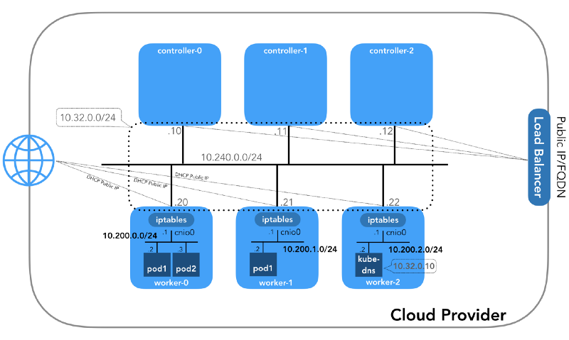
You may notice that there are also at least three private subnets here! A little patience, and they will all be considered. Remember that although we refer to very specific IP prefixes, they are simply taken from Kubernetes The Hard Way , so they have only local significance, and you are free to choose any other address block for your environment in accordance with RFC 1918 . For the case of IPv6 there will be a separate article in the blog.
This is an internal network, of which all nodes are part. It is determined by the
(
(
Each instance will have two IP addresses: private from the host's network (controllers -
All nodes must be able to ping each other if the security policies are correct (and if
This is the network in which they live. Each working node uses a subnet of this network. In our case,
To understand how everything is set up, let's take a step back and look at the network model Kubernetes , which requires the following:
Implementation of all this is possible in different ways, and Kubernetes passes the network configuration to the CNI plugin .

Linux provides seven different namespaces (
Let's go down to the ground and see how it all relates to the cluster. First, the network plug-ins in Kubernetes are diverse, and the CNI plug-ins are one of them ( why not CNM? ). Kubelet on each node tells the container's executable environment which network plugin to use. The Container Network Interface ( CNI ) is located between the executable container environment and the network implementation. And already CNI plugin configures the network.
The real binaries of the CNI plugin are in
Please note that the call options for
First of all, Kubernetes creates a network namespace for the hearth, even before calling any plugins. This is implemented using a special
The configuration used for CNI indicates the use of the

A veth-pair will also be configured to connect the hearth to the newly created bridge:
To assign L3 information, such as IP addresses, the IPAM plugin (
And the last important detail: we requested masquerading (

Now we are ready to customize the hearth. We will look at all the network spaces of the names of one of the working nodes and analyze one of them after creating the
Using the
You can also list all network namespaces using
To see all the processes running in the network space
It is seen that in addition to the
Now let's see what
More details:
We see the name of the pod -
Knowing the containerd namespace (
... and
The
Remember that processes with PID 27331 and 27355 are running in the network name space
... and:
Now we know exactly which containers are running in this pod (

How is this one under (
For these purposes, we use
... and
Thus, it is confirmed that the IP address obtained earlier through the
We see that
To make sure of this completely, let's see:
Great, with the virtual link, now everything is clear. With the help of
So, the picture is as follows:
How do we actually forward traffic? Let's look at the routing table in the network namespace:
At least we know how to get to the root namespace (
We know how to forward packets to the VPC Router (the VPC has a “hidden” [implicit] router, which usually has a second address from the main IP subnet address space). Now: does the VPC Router know how to get to the network of each pod? No, he does not know, so it is assumed that the routes will be configured by the CNI plugin or manually (as in the manual). Apparently, AWS CNI-plugin does exactly that for us in AWS. Remember that there are many plug-ins CNI , and we consider an example of the simplest network configuration :
(
We get:
Pings from one container to another must be successful:
To understand the traffic flow, you can look at the packets using
The source IP from 10.200.0.21 is transmitted to the IP address of the node 10.240.0.20.
In iptables, you can see that the counters are increasing:
On the other hand, if you remove
Ping still has to go:
And in this case - without using NAT:
So, we checked that "all containers can communicate with any other containers without using NAT".
You may have noticed in the example with
There are different ways to publish a service; The default type is
(
How exactly? .. Again
As soon as packets are created by the process (
The following targets correspond to TCP packets sent to port 53 at 10.32.0.10, and are broadcast to recipient 10.200.0.27 with port 53:
The same is true for UDP packets (receiver 10.32.0.10:53 → 10.200.0.27:53):
There are other types of
Under is now available from the internet as
The packet is sent from worker-0 to worker-1 , where it finds its recipient:
Is this scheme ideal? Perhaps not, but it works. In this case, the programmed
In other words, the address for the receiver of packets with port 31088 is broadcast on 10.200.1.18. The port is also broadcast, from 31088 to 80.
We did not touch on another type of services -
It might seem that there is a lot of information here, but we only touched the tip of the iceberg. In the future, I'm going to talk about IPv6, IPVS, eBPF and a couple of interesting CNI plug-ins.
Read also in our blog:
Aside from the fact that the Kelsey Hightower’s Kubernetes The Hard Way manual just works ( even on AWS! ), I liked that the network was kept clean and simple; and this is a great opportunity to understand the role, for example, of the Container Network Interface ( CNI ). Having said that, I would add that the Kubernetes network is not really very intuitive, especially for beginners ... and also do not forget that "such a thing as a network for containers simply does not exist ."
')
Although there are already some good materials on this topic (see links here ), I could not find such an example that I would combine everything I needed with the conclusions of commands that network engineers love and hate so much, demonstrating what is actually happening behind the scenes. That's why I decided to collect information from a variety of sources - I hope this will help you better understand how everything is connected with each other. This knowledge is important not only to check yourself, but also to simplify the process of diagnosing problems. You can follow this example in your cluster from Kubernetes The Hard Way : all IP addresses and settings are taken from there (as at the state of commits in May 2018, before using Nabla containers ).
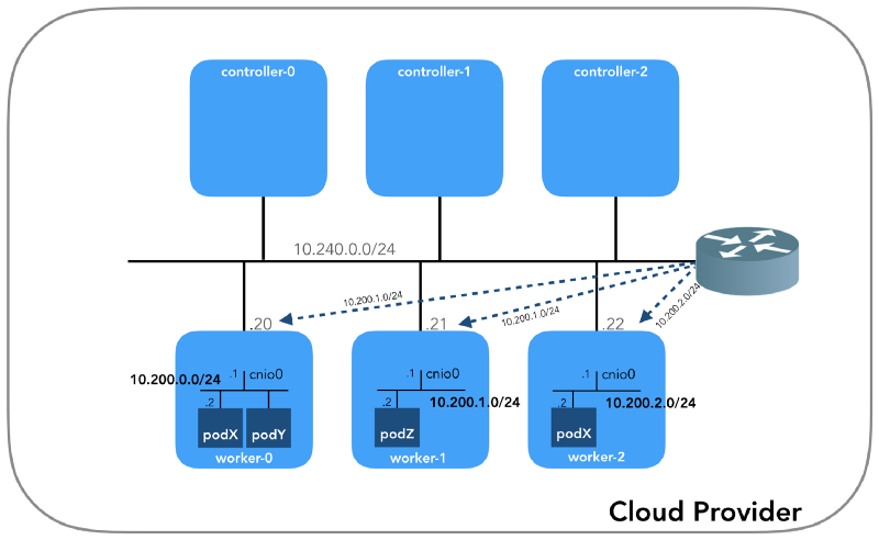
And we will start from the end, when we have three controllers and three working nodes:
You may notice that there are also at least three private subnets here! A little patience, and they will all be considered. Remember that although we refer to very specific IP prefixes, they are simply taken from Kubernetes The Hard Way , so they have only local significance, and you are free to choose any other address block for your environment in accordance with RFC 1918 . For the case of IPv6 there will be a separate article in the blog.
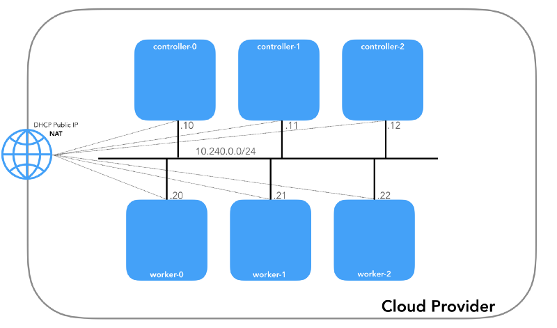
Host Network (10.240.0.0/24)
This is an internal network, of which all nodes are part. It is determined by the
--private-network-ip flag in the GCP or by the --private-ip-address option in AWS when allocating computing resources.Initializing controller nodes in GCP
for i in 0 1 2; do gcloud compute instances create controller-${i} \ # ... --private-network-ip 10.240.0.1${i} \ # ... done (
controllers_gcp.sh )Initializing controller nodes in AWS
for i in 0 1 2; do declare controller_id${i}=`aws ec2 run-instances \ # ... --private-ip-address 10.240.0.1${i} \ # ... done (
controllers_aws.sh )Each instance will have two IP addresses: private from the host's network (controllers -
10.240.0.1${i}/24 , workers - 10.240.0.2${i}/24 ) and public, assigned by the cloud provider, which we will talk about later how to get to NodePorts .Gcp
$ gcloud compute instances list NAME ZONE MACHINE_TYPE PREEMPTIBLE INTERNAL_IP EXTERNAL_IP STATUS controller-0 us-west1-c n1-standard-1 10.240.0.10 35.231.XXX.XXX RUNNING worker-1 us-west1-c n1-standard-1 10.240.0.21 35.231.XX.XXX RUNNING ... AWS
$ aws ec2 describe-instances --query 'Reservations[].Instances[].[Tags[?Key==`Name`].Value[],PrivateIpAddress,PublicIpAddress]' --output text | sed '$!N;s/\n/ /' 10.240.0.10 34.228.XX.XXX controller-0 10.240.0.21 34.173.XXX.XX worker-1 ... All nodes must be able to ping each other if the security policies are correct (and if
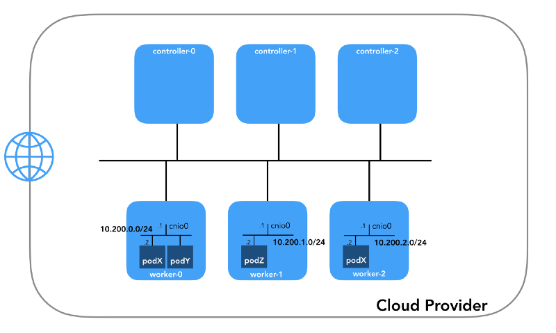
ping installed on the host).Network of hearth (10.200.0.0/16)
This is the network in which they live. Each working node uses a subnet of this network. In our case,
POD_CIDR=10.200.${i}.0/24 for a worker-${i} .To understand how everything is set up, let's take a step back and look at the network model Kubernetes , which requires the following:
- All containers can communicate with any other containers without using NAT.
- All nodes can communicate with all containers (and vice versa) without using NAT.
- The IP that sees the container should be the same as others see it.
Implementation of all this is possible in different ways, and Kubernetes passes the network configuration to the CNI plugin .
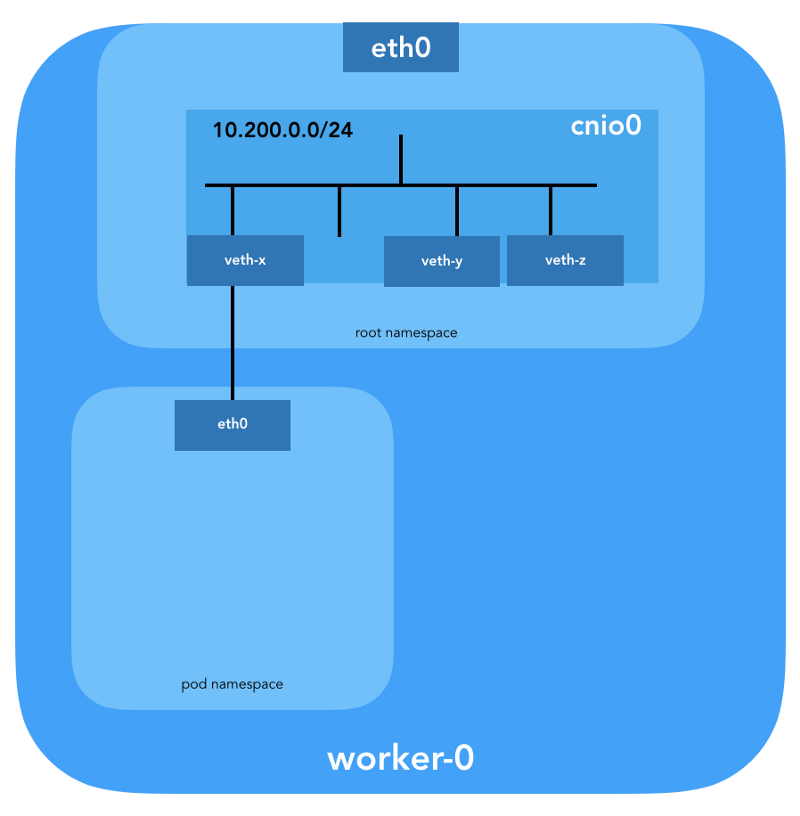
“The CNI plugin is responsible for adding a network interface in the container's network namespace (for example, one end of a veth pair ) and making necessary changes on the host (for example, connecting the second end of the veth to the bridge). Then he must assign the IP interface and configure the routes according to the section “IP Address Management” by calling the necessary IPAM plugin. ” (from Container Network Interface Specification )
Network Namespace
“The namespace wraps the global system resource into an abstraction, which is visible to the processes in this namespace in such a way that they have their own isolated copy of the global resource. Changes in the global resource are visible to other processes in this namespace, but not visible to other processes. ” ( from namespaces man page )
Linux provides seven different namespaces (
Cgroup , IPC , Network , Mount , PID , User , UTS ). Network ( Network ) namespaces ( CLONE_NEWNET ) define network resources that are available to the process: “Each network namespace has its own network devices, IP addresses, IP routing tables, /proc/net directory, port numbers, and so on” ( from the article " Namespaces in operation ") .Virtual Ethernet devices (Veth)
“Virtual network pair (veth) offers an abstraction in the form of a“ pipe ”that can be used to create tunnels between network name spaces or to create a bridge to a physical network device in another network space. When the namespace is freed, all veth devices in it are destroyed. ” (from the network namespaces man page )
Let's go down to the ground and see how it all relates to the cluster. First, the network plug-ins in Kubernetes are diverse, and the CNI plug-ins are one of them ( why not CNM? ). Kubelet on each node tells the container's executable environment which network plugin to use. The Container Network Interface ( CNI ) is located between the executable container environment and the network implementation. And already CNI plugin configures the network.
“The CNI plugin is selected by passing the command line--network-plugin=cnito Kubelet. Kubelet reads a file from--cni-conf-dir(the default is/etc/cni/net.d) and uses the CNI configuration from this file to configure the network for each hearth. ” (from Network Plugin Requirements )
The real binaries of the CNI plugin are in
-- cni-bin-dir (the default is /opt/cni/bin ).Please note that the call options for
kubelet.service include --network-plugin=cni : [Service] ExecStart=/usr/local/bin/kubelet \\ --config=/var/lib/kubelet/kubelet-config.yaml \\ --network-plugin=cni \\ ... First of all, Kubernetes creates a network namespace for the hearth, even before calling any plugins. This is implemented using a special
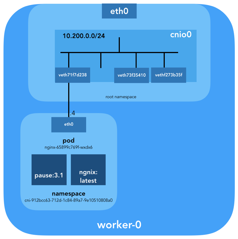
pause container, which “serves as the“ parent container ”for all pod containers” (from the article “ The Almighty Pause Container ”) . Kubernetes then executes the CNI plugin to attach the pause container to the network. All pod containers use the network namespace ( netns ) of this pause container. { "cniVersion": "0.3.1", "name": "bridge", "type": "bridge", "bridge": "cnio0", "isGateway": true, "ipMasq": true, "ipam": { "type": "host-local", "ranges": [ [{"subnet": "${POD_CIDR}"}] ], "routes": [{"dst": "0.0.0.0/0"}] } } The configuration used for CNI indicates the use of the
bridge plug-in to configure the Linux software bridge (L2) in the root namespace called cnio0 (the default name is cni0 ), which acts as a gateway ( "isGateway": true ).A veth-pair will also be configured to connect the hearth to the newly created bridge:
To assign L3 information, such as IP addresses, the IPAM plugin (
ipam ) is called. In this case, the host-local type is used, “which stores the state locally on the host file system, which ensures the uniqueness of IP addresses on one host” (from the host-local ) . The IPAM plugin returns this information to the previous plug-in ( bridge ), due to which all routes specified in the config can be configured ( "routes": [{"dst": "0.0.0.0/0"}] ). If gw not specified, it is taken from the subnet . The default route is also configured in the network pod names, pointing to the bridge (which is configured as the first IP subnet of the sub).And the last important detail: we requested masquerading (
"ipMasq": true ) of the traffic originating from the network podov. In fact, we do not need NAT here, but this is the config in Kubernetes The Hard Way . Therefore, for the sake of completeness, I must mention that the bridge plugin's iptables entries are configured for this particular example. All packets from the pod, the recipient of which is not in the range of 224.0.0.0/4 , will be behind NAT , which does not quite meet the requirement “all containers can communicate with any other containers without using NAT”. Well, we'll prove why NAT is not needed ...Routing
Now we are ready to customize the hearth. We will look at all the network spaces of the names of one of the working nodes and analyze one of them after creating the
nginx deployment from here . We use lsns with the -t option to select the desired type of namespace (i.e. net ): ubuntu@worker-0:~$ sudo lsns -t net NS TYPE NPROCS PID USER COMMAND 4026532089 net 113 1 root /sbin/init 4026532280 net 2 8046 root /pause 4026532352 net 4 16455 root /pause 4026532426 net 3 27255 root /pause Using the
-i option to ls we can find their inode numbers: ubuntu@worker-0:~$ ls -1i /var/run/netns 4026532352 cni-1d85bb0c-7c61-fd9f-2adc-f6e98f7a58af 4026532280 cni-7cec0838-f50c-416a-3b45-628a4237c55c 4026532426 cni-912bcc63-712d-1c84-89a7-9e10510808a0 You can also list all network namespaces using
ip netns : ubuntu@worker-0:~$ ip netns cni-912bcc63-712d-1c84-89a7-9e10510808a0 (id: 2) cni-1d85bb0c-7c61-fd9f-2adc-f6e98f7a58af (id: 1) cni-7cec0838-f50c-416a-3b45-628a4237c55c (id: 0) To see all the processes running in the network space
cni-912bcc63–712d-1c84–89a7–9e10510808a0 ( 4026532426 ), you can run, for example, the following command: ubuntu@worker-0:~$ sudo ls -l /proc/[1-9]*/ns/net | grep 4026532426 | cut -f3 -d"/" | xargs ps -p PID TTY STAT TIME COMMAND 27255 ? Ss 0:00 /pause 27331 ? Ss 0:00 nginx: master process nginx -g daemon off; 27355 ? S 0:00 nginx: worker process It is seen that in addition to the
pause in this section, we launched nginx . The pause container shares the net and ipc namespaces with all other pod containers. Remember PID from pause - 27255; we will return to it.Now let's see what
kubectl tells about this kubectl : $ kubectl get pods -o wide | grep nginx nginx-65899c769f-wxdx6 1/1 Running 0 5d 10.200.0.4 worker-0 More details:
$ kubectl describe pods nginx-65899c769f-wxdx6 Name: nginx-65899c769f-wxdx6 Namespace: default Node: worker-0/10.240.0.20 Start Time: Thu, 05 Jul 2018 14:20:06 -0400 Labels: pod-template-hash=2145573259 run=nginx Annotations: <none> Status: Running IP: 10.200.0.4 Controlled By: ReplicaSet/nginx-65899c769f Containers: nginx: Container ID: containerd://4c0bd2e2e5c0b17c637af83376879c38f2fb11852921b12413c54ba49d6983c7 Image: nginx ... We see the name of the pod -
nginx-65899c769f-wxdx6 - and the ID of one of its containers ( nginx ), but not a word about pause so far. Let's dig deeper the working node to match all the data. Remember that Kubernetes The Hard Way does not use Docker , so for details on the container we refer to the console utility containerd - ctr (see also the article “ Integration of containerd with Kubernetes, replacing Docker, is ready for production ” - approx. Transl. ) : ubuntu@worker-0:~$ sudo ctr namespaces ls NAME LABELS k8s.io Knowing the containerd namespace (
k8s.io ), you can get the nginx container ID: ubuntu@worker-0:~$ sudo ctr -n k8s.io containers ls | grep nginx 4c0bd2e2e5c0b17c637af83376879c38f2fb11852921b12413c54ba49d6983c7 docker.io/library/nginx:latest io.containerd.runtime.v1.linux ... and
pause too: ubuntu@worker-0:~$ sudo ctr -n k8s.io containers ls | grep pause 0866803b612f2f55e7b6b83836bde09bd6530246239b7bde1e49c04c7038e43a k8s.gcr.io/pause:3.1 io.containerd.runtime.v1.linux 21640aea0210b320fd637c22ff93b7e21473178de0073b05de83f3b116fc8834 k8s.gcr.io/pause:3.1 io.containerd.runtime.v1.linux d19b1b1c92f7cc90764d4f385e8935d121bca66ba8982bae65baff1bc2841da6 k8s.gcr.io/pause:3.1 io.containerd.runtime.v1.linux The
nginx container ID ending in …983c7 is the same as what we got from kubectl . Let's see if we can figure out which pause container belongs to the nginx hearth: ubuntu@worker-0:~$ sudo ctr -n k8s.io task ls TASK PID STATUS ... d19b1b1c92f7cc90764d4f385e8935d121bca66ba8982bae65baff1bc2841da6 27255 RUNNING 4c0bd2e2e5c0b17c637af83376879c38f2fb11852921b12413c54ba49d6983c7 27331 RUNNING Remember that processes with PID 27331 and 27355 are running in the network name space
cni-912bcc63–712d-1c84–89a7–9e10510808a0 ? ubuntu@worker-0:~$ sudo ctr -n k8s.io containers info d19b1b1c92f7cc90764d4f385e8935d121bca66ba8982bae65baff1bc2841da6 { "ID": "d19b1b1c92f7cc90764d4f385e8935d121bca66ba8982bae65baff1bc2841da6", "Labels": { "io.cri-containerd.kind": "sandbox", "io.kubernetes.pod.name": "nginx-65899c769f-wxdx6", "io.kubernetes.pod.namespace": "default", "io.kubernetes.pod.uid": "0b35e956-8080-11e8-8aa9-0a12b8818382", "pod-template-hash": "2145573259", "run": "nginx" }, "Image": "k8s.gcr.io/pause:3.1", ... ... and:
ubuntu@worker-0:~$ sudo ctr -n k8s.io containers info 4c0bd2e2e5c0b17c637af83376879c38f2fb11852921b12413c54ba49d6983c7 { "ID": "4c0bd2e2e5c0b17c637af83376879c38f2fb11852921b12413c54ba49d6983c7", "Labels": { "io.cri-containerd.kind": "container", "io.kubernetes.container.name": "nginx", "io.kubernetes.pod.name": "nginx-65899c769f-wxdx6", "io.kubernetes.pod.namespace": "default", "io.kubernetes.pod.uid": "0b35e956-8080-11e8-8aa9-0a12b8818382" }, "Image": "docker.io/library/nginx:latest", ... Now we know exactly which containers are running in this pod (
nginx-65899c769f-wxdx6 ) and the network namespace ( cni-912bcc63–712d-1c84–89a7–9e10510808a0 ):- nginx (ID:
4c0bd2e2e5c0b17c637af83376879c38f2fb11852921b12413c54ba49d6983c7); - pause (ID:
d19b1b1c92f7cc90764d4f385e8935d121bca66ba8982bae65baff1bc2841da6).
How is this one under (
nginx-65899c769f-wxdx6 ) connected to the network? Let's use the previously received PID 27255 from pause to launch commands in its network namespace ( cni-912bcc63–712d-1c84–89a7–9e10510808a0 ): ubuntu@worker-0:~$ sudo ip netns identify 27255 cni-912bcc63-712d-1c84-89a7-9e10510808a0 For these purposes, we use
nsenter with the -t option that defines the target PID, and -n without specifying a file to get into the network namespace of the target process (27255). This is what the ip link show will say: ubuntu@worker-0:~$ sudo nsenter -t 27255 -n ip link show 1: lo: <LOOPBACK,UP,LOWER_UP> mtu 65536 qdisc noqueue state UNKNOWN mode DEFAULT group default qlen 1000 link/loopback 00:00:00:00:00:00 brd 00:00:00:00:00:00 3: eth0@if7: <BROADCAST,MULTICAST,UP,LOWER_UP> mtu 1500 qdisc noqueue state UP mode DEFAULT group default link/ether 0a:58:0a:c8:00:04 brd ff:ff:ff:ff:ff:ff link-netnsid 0 ... and
ifconfig eth0 : ubuntu@worker-0:~$ sudo nsenter -t 27255 -n ifconfig eth0 eth0: flags=4163<UP,BROADCAST,RUNNING,MULTICAST> mtu 1500 inet 10.200.0.4 netmask 255.255.255.0 broadcast 0.0.0.0 inet6 fe80::2097:51ff:fe39:ec21 prefixlen 64 scopeid 0x20<link> ether 0a:58:0a:c8:00:04 txqueuelen 0 (Ethernet) RX packets 540 bytes 42247 (42.2 KB) RX errors 0 dropped 0 overruns 0 frame 0 TX packets 177 bytes 16530 (16.5 KB) TX errors 0 dropped 0 overruns 0 carrier 0 collisions 0 Thus, it is confirmed that the IP address obtained earlier through the
kubectl get pod is configured on the eth0 interface of the submenu. This interface is part of a veth pair , one end of which is in the hearth, and the other is in the root namespace. To find out the interface of the second end, use ethtool : ubuntu@worker-0:~$ sudo ip netns exec cni-912bcc63-712d-1c84-89a7-9e10510808a0 ethtool -S eth0 NIC statistics: peer_ifindex: 7 We see that
ifindex is 7. ifindex that it is in the root namespace. This can be done using ip link : ubuntu@worker-0:~$ ip link | grep '^7:' 7: veth71f7d238@if3: <BROADCAST,MULTICAST,UP,LOWER_UP> mtu 1500 qdisc noqueue master cnio0 state UP mode DEFAULT group default To make sure of this completely, let's see:
ubuntu@worker-0:~$ sudo cat /sys/class/net/veth71f7d238/ifindex 7 Great, with the virtual link, now everything is clear. With the help of
brctl let's see who else is connected to the Linux-bridge: ubuntu@worker-0:~$ brctl show cnio0 bridge name bridge id STP enabled interfaces cnio0 8000.0a580ac80001 no veth71f7d238 veth73f35410 vethf273b35f So, the picture is as follows:
Routing check
How do we actually forward traffic? Let's look at the routing table in the network namespace:
ubuntu@worker-0:~$ sudo ip netns exec cni-912bcc63-712d-1c84-89a7-9e10510808a0 ip route show default via 10.200.0.1 dev eth0 10.200.0.0/24 dev eth0 proto kernel scope link src 10.200.0.4 At least we know how to get to the root namespace (
default via 10.200.0.1 ). Now let's look at the host routing table: ubuntu@worker-0:~$ ip route list default via 10.240.0.1 dev eth0 proto dhcp src 10.240.0.20 metric 100 10.200.0.0/24 dev cnio0 proto kernel scope link src 10.200.0.1 10.240.0.0/24 dev eth0 proto kernel scope link src 10.240.0.20 10.240.0.1 dev eth0 proto dhcp scope link src 10.240.0.20 metric 100 We know how to forward packets to the VPC Router (the VPC has a “hidden” [implicit] router, which usually has a second address from the main IP subnet address space). Now: does the VPC Router know how to get to the network of each pod? No, he does not know, so it is assumed that the routes will be configured by the CNI plugin or manually (as in the manual). Apparently, AWS CNI-plugin does exactly that for us in AWS. Remember that there are many plug-ins CNI , and we consider an example of the simplest network configuration :
Deep immersion in NAT
kubectl create -f busybox.yaml create two identical busybox containers with Replication Controller: apiVersion: v1 kind: ReplicationController metadata: name: busybox0 labels: app: busybox0 spec: replicas: 2 selector: app: busybox0 template: metadata: name: busybox0 labels: app: busybox0 spec: containers: - image: busybox command: - sleep - "3600" imagePullPolicy: IfNotPresent name: busybox restartPolicy: Always (
busybox.yaml )We get:
$ kubectl get pods -o wide NAME READY STATUS RESTARTS AGE IP NODE busybox0-g6pww 1/1 Running 0 4s 10.200.1.15 worker-1 busybox0-rw89s 1/1 Running 0 4s 10.200.0.21 worker-0 ... Pings from one container to another must be successful:
$ kubectl exec -it busybox0-rw89s -- ping -c 2 10.200.1.15 PING 10.200.1.15 (10.200.1.15): 56 data bytes 64 bytes from 10.200.1.15: seq=0 ttl=62 time=0.528 ms 64 bytes from 10.200.1.15: seq=1 ttl=62 time=0.440 ms --- 10.200.1.15 ping statistics --- 2 packets transmitted, 2 packets received, 0% packet loss round-trip min/avg/max = 0.440/0.484/0.528 ms To understand the traffic flow, you can look at the packets using
tcpdump or conntrack : ubuntu@worker-0:~$ sudo conntrack -L | grep 10.200.1.15 icmp 1 29 src=10.200.0.21 dst=10.200.1.15 type=8 code=0 id=1280 src=10.200.1.15 dst=10.240.0.20 type=0 code=0 id=1280 mark=0 use=1 The source IP from 10.200.0.21 is transmitted to the IP address of the node 10.240.0.20.
ubuntu@worker-1:~$ sudo conntrack -L | grep 10.200.1.15 icmp 1 28 src=10.240.0.20 dst=10.200.1.15 type=8 code=0 id=1280 src=10.200.1.15 dst=10.240.0.20 type=0 code=0 id=1280 mark=0 use=1 In iptables, you can see that the counters are increasing:
ubuntu@worker-0:~$ sudo iptables -t nat -Z POSTROUTING -L -v Chain POSTROUTING (policy ACCEPT 0 packets, 0 bytes) pkts bytes target prot opt in out source destination ... 5 324 CNI-be726a77f15ea47ff32947a3 all -- any any 10.200.0.0/24 anywhere /* name: "bridge" id: "631cab5de5565cc432a3beca0e2aece0cef9285482b11f3eb0b46c134e457854" */ Zeroing chain `POSTROUTING' On the other hand, if you remove
"ipMasq": true from the configuration of the CNI plug-in, you can see the following (this operation is performed exclusively for educational purposes - we do not recommend changing the config on a running cluster!): $ kubectl get pods -o wide NAME READY STATUS RESTARTS AGE IP NODE busybox0-2btxn 1/1 Running 0 16s 10.200.0.15 worker-0 busybox0-dhpx8 1/1 Running 0 16s 10.200.1.13 worker-1 ... Ping still has to go:
$ kubectl exec -it busybox0-2btxn -- ping -c 2 10.200.1.13 PING 10.200.1.6 (10.200.1.6): 56 data bytes 64 bytes from 10.200.1.6: seq=0 ttl=62 time=0.515 ms 64 bytes from 10.200.1.6: seq=1 ttl=62 time=0.427 ms --- 10.200.1.6 ping statistics --- 2 packets transmitted, 2 packets received, 0% packet loss round-trip min/avg/max = 0.427/0.471/0.515 ms And in this case - without using NAT:
ubuntu@worker-0:~$ sudo conntrack -L | grep 10.200.1.13 icmp 1 29 src=10.200.0.15 dst=10.200.1.13 type=8 code=0 id=1792 src=10.200.1.13 dst=10.200.0.15 type=0 code=0 id=1792 mark=0 use=1 So, we checked that "all containers can communicate with any other containers without using NAT".
ubuntu@worker-1:~$ sudo conntrack -L | grep 10.200.1.13 icmp 1 27 src=10.200.0.15 dst=10.200.1.13 type=8 code=0 id=1792 src=10.200.1.13 dst=10.200.0.15 type=0 code=0 id=1792 mark=0 use=1 Cluster Network (10.32.0.0/24)
You may have noticed in the example with
busybox that the IP addresses allocated to the busybox pod were different in each case. What if we wanted to make these containers available for communication from other platforms? It would be possible to take the current pod IP addresses, but they will change. For this reason, you need to configure the resource Service , which will proxy requests to a variety of short-lived pods.“Service in Kubernetes is an abstraction that defines a logical set of hearths and a policy by which they can be accessed.” (from Kubernetes Services documentation)
There are different ways to publish a service; The default type is
ClusterIP , which configures the IP address from the cluster CIDR block (that is, it is accessible only from the cluster). One such example is the DNS Cluster Add-on configured in Kubernetes The Hard Way. # ... apiVersion: v1 kind: Service metadata: name: kube-dns namespace: kube-system labels: k8s-app: kube-dns kubernetes.io/cluster-service: "true" addonmanager.kubernetes.io/mode: Reconcile kubernetes.io/name: "KubeDNS" spec: selector: k8s-app: kube-dns clusterIP: 10.32.0.10 ports: - name: dns port: 53 protocol: UDP - name: dns-tcp port: 53 protocol: TCP # ... (
kube-dns.yaml )kubectl shows that Service remembers endpoints and translates them: $ kubectl -n kube-system describe services ... Selector: k8s-app=kube-dns Type: ClusterIP IP: 10.32.0.10 Port: dns 53/UDP TargetPort: 53/UDP Endpoints: 10.200.0.27:53 Port: dns-tcp 53/TCP TargetPort: 53/TCP Endpoints: 10.200.0.27:53 ... How exactly? .. Again
iptables . Let's go through the rules created for this example. Their full list can be seen with the iptables-save command.As soon as packets are created by the process (
OUTPUT ) or arrive at the network interface ( PREROUTING ), they pass through the following iptables chains: -A PREROUTING -m comment --comment "kubernetes service portals" -j KUBE-SERVICES -A OUTPUT -m comment --comment "kubernetes service portals" -j KUBE-SERVICES The following targets correspond to TCP packets sent to port 53 at 10.32.0.10, and are broadcast to recipient 10.200.0.27 with port 53:
-A KUBE-SERVICES -d 10.32.0.10/32 -p tcp -m comment --comment "kube-system/kube-dns:dns-tcp cluster IP" -m tcp --dport 53 -j KUBE-SVC-ERIFXISQEP7F7OF4 -A KUBE-SVC-ERIFXISQEP7F7OF4 -m comment --comment "kube-system/kube-dns:dns-tcp" -j KUBE-SEP-32LPCMGYG6ODGN3H -A KUBE-SEP-32LPCMGYG6ODGN3H -p tcp -m comment --comment "kube-system/kube-dns:dns-tcp" -m tcp -j DNAT --to-destination 10.200.0.27:53 The same is true for UDP packets (receiver 10.32.0.10:53 → 10.200.0.27:53):
-A KUBE-SERVICES -d 10.32.0.10/32 -p udp -m comment --comment "kube-system/kube-dns:dns cluster IP" -m udp --dport 53 -j KUBE-SVC-TCOU7JCQXEZGVUNU -A KUBE-SVC-TCOU7JCQXEZGVUNU -m comment --comment "kube-system/kube-dns:dns" -j KUBE-SEP-LRUTK6XRXU43VLIG -A KUBE-SEP-LRUTK6XRXU43VLIG -p udp -m comment --comment "kube-system/kube-dns:dns" -m udp -j DNAT --to-destination 10.200.0.27:53 There are other types of
Services in Kubernetes. In particular, Kubernetes The Hard Way NodePort about NodePort - see Smoke Test: Services . kubectl expose deployment nginx --port 80 --type NodePort NodePort publishes a service on the IP address of each node, placing it on a static port (it is called NodePort ). The NodePort service can NodePort be accessed from outside the cluster. You can check the selected port (in this case - 31088) with the help of kubectl : $ kubectl describe services nginx ... Type: NodePort IP: 10.32.0.53 Port: <unset> 80/TCP TargetPort: 80/TCP NodePort: <unset> 31088/TCP Endpoints: 10.200.1.18:80 ... Under is now available from the internet as
http://${EXTERNAL_IP}:31088/ . Here, EXTERNAL_IP is the public IP address of any working instance . In this example, I used the public IP address worker-0 . The request is obtained by a node with an IP address of 10.240.0.20 (the cloud provider is in public NAT), but the service is actually running on another node ( worker-1 , which can be seen at the endpoint's IP address - 10.200.1.18): ubuntu@worker-0:~$ sudo conntrack -L | grep 31088 tcp 6 86397 ESTABLISHED src=173.38.XXX.XXX dst=10.240.0.20 sport=30303 dport=31088 src=10.200.1.18 dst=10.240.0.20 sport=80 dport=30303 [ASSURED] mark=0 use=1 The packet is sent from worker-0 to worker-1 , where it finds its recipient:
ubuntu@worker-1:~$ sudo conntrack -L | grep 80 tcp 6 86392 ESTABLISHED src=10.240.0.20 dst=10.200.1.18 sport=14802 dport=80 src=10.200.1.18 dst=10.240.0.20 sport=80 dport=14802 [ASSURED] mark=0 use=1 Is this scheme ideal? Perhaps not, but it works. In this case, the programmed
iptables rules are: -A KUBE-NODEPORTS -p tcp -m comment --comment "default/nginx:" -m tcp --dport 31088 -j KUBE-SVC-4N57TFCL4MD7ZTDA -A KUBE-SVC-4N57TFCL4MD7ZTDA -m comment --comment "default/nginx:" -j KUBE-SEP-UGTFMET44DQG7H7H -A KUBE-SEP-UGTFMET44DQG7H7H -p tcp -m comment --comment "default/nginx:" -m tcp -j DNAT --to-destination 10.200.1.18:80 In other words, the address for the receiver of packets with port 31088 is broadcast on 10.200.1.18. The port is also broadcast, from 31088 to 80.
We did not touch on another type of services -
LoadBalancer , - which makes the service publicly available with the help of the cloud provider’s load balancer, but the article has already turned out to be large.Conclusion
It might seem that there is a lot of information here, but we only touched the tip of the iceberg. In the future, I'm going to talk about IPv6, IPVS, eBPF and a couple of interesting CNI plug-ins.
PS from translator
Read also in our blog:
- “ An Illustrated Network Guide for Kubernetes ”;
- " Comparison of the performance of network solutions for Kubernetes ";
- “ Experiments with kube-proxy and unavailability of a node in Kubernetes ”;
- " Improving the reliability of Kubernetes: how to quickly notice that the node has fallen ";
- « Play with Kubernetes — K8s »;
- « Kubernetes » ( , Kubernetes) ;
- « Container Networking Interface (CNI) — Linux- ».
Source: https://habr.com/ru/post/420813/
All Articles