Learn OpenGL. Lesson 5.9 - Deferred Rendering

In previous articles we used forward lighting (forward rendering or forward shading) . This is a simple approach in which we draw an object with all the light sources taken into account, then we draw the next object along with all the lights on it, and so on for each object. It is quite simple to understand and implement, but at the same time it turns out rather slowly in terms of performance: for each object you have to go through all the sources of light. In addition, direct lighting works inefficiently on scenes with a large number of overlapping objects, since most of the pixel shader calculations are not useful and will be overwritten with values for closer objects.
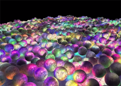
Deferred lighting or deferred rendering (deferred shading or deferred rendering) bypasses this problem and drastically changes the way we draw objects. This gives new opportunities to significantly optimize scenes with a large number of light sources, allowing you to draw hundreds or even thousands of light sources with acceptable speed. Below is a scene from 1847 point sources of light, drawn using deferred lighting (image provided by Hannes Nevalainen). Something similar would have been impossible with a direct calculation of the lighting:
Part 1. Start
- Opengl
- Creating a window
- Hello window
- Hello triangle
- Shaders
- Textures
- Transformations
- Coordinate systems
- Camera
Part 2. Basic lighting
Part 3. Loading 3D Models
')
Part 4. OpenGL advanced features
- Depth test
- Stencil test
- Mixing colors
- Face clipping
- Frame buffer
- Cubic cards
- Advanced data handling
- Advanced GLSL
- Geometric shader
- Instancing
- Smoothing
Part 5. Advanced Lighting
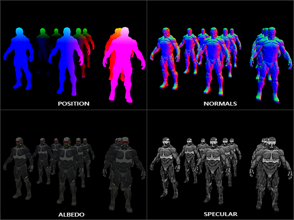
The idea of deferred lighting is that we set aside the most computationally complex parts (such as lighting) for later. Deferred lighting consists of two passes: in the first pass, geometric (geometry pass) , the whole scene is drawn and various information is saved into a set of textures, called G-buffer. For example: positions, colors, normals and / or specularity of the surface for each pixel. The graphic information stored in the G-buffer is later used to calculate the illumination. The following is the G-Buffer content for one frame:
In the second pass, called the lighting pass, we use G-buffer textures when we draw a full-screen rectangle. Instead of using the vertex and fragment shaders separately for each object, we draw pixel by pixel the entire scene at once. The lighting calculation remains exactly the same as with the direct pass, but we take the necessary data only from the G-buffer and shader variables (uniforms) , and not from the vertex shader.
The image below shows the overall drawing process well.
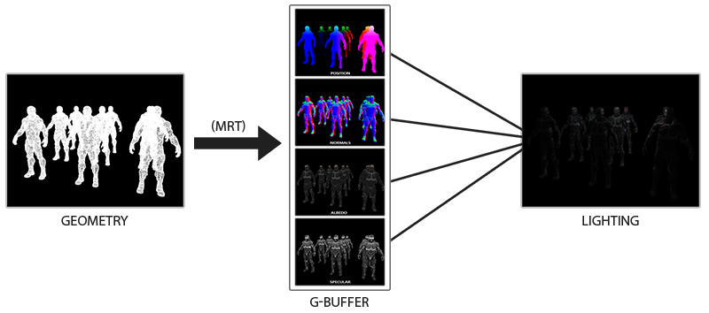
The main advantage is that the information stored in the G-buffer belongs to the closest fragments that are not obscured by anything: the depth test leaves only them. Because of this, we calculate the lighting for each pixel only once, without doing any work. Moreover, deferred illumination gives us the opportunity for further optimizations, allowing us to use much more light sources than with direct illumination.
However, there are a couple of drawbacks: the G-buffer stores a large amount of information about the scene. In addition, position type data is required to be stored with high accuracy; as a result, the G-buffer takes up quite a lot of memory space. Another disadvantage is that we will not be able to use translucent objects (since information is stored in the buffer only for the nearest surface) and smoothing of the MSAA type will not work either. There are several workarounds to solve these problems, they are discussed at the end of the article.
(Approx. Trans. - G-buffer takes up a lot of memory space. For example, for a 1920 * 1080 screen and using 128 bits per pixel, the buffer will take 33mb. The requirements for memory bandwidth grow - much more data is written and read)
G-buffer
G-Buffer is the texture used to store the lighting-related information used in the last rendering pass. Let's see what information we need to calculate the lighting for direct rendering:
- 3d position vector: used to find out the position of a fragment relative to the camera and light sources.
- Diffuse color of the fragment (reflectivity for red, green and blue - in general, color).
- 3d normal vector (to determine at what angle the light falls on the surface)
- float for storing the mirror component
- The position of the light source and its color.
- Camera position.
With the help of these variables, we can calculate the lighting according to the Blinna-Phong model already familiar to us. The color and position of the light source, as well as the position of the camera can be common variables, but the other values will be different for each image fragment. If we pass exactly the same data into the final pass of deferred lighting, which we would use in the direct pass, we will get the same result, despite the fact that we will draw fragments in the usual 2D rectangle.
In OpenGL, there are no restrictions on what we can store in the texture, so it makes sense to store all the information in one or more screen-sized textures (called G-Buffer) and use them all in the lighting pass. Since the size of the textures and the screen is the same, we will get the same input data as in direct lighting.
In pseudocode, the overall picture looks like this:
while(...) // render loop { // 1. : / g- glBindFramebuffer(GL_FRAMEBUFFER, gBuffer); glClear(GL_COLOR_BUFFER_BIT | GL_DEPTH_BUFFER_BIT); gBufferShader.use(); for(Object obj : Objects) { ConfigureShaderTransformsAndUniforms(); obj.Draw(); } // 2. : g- glBindFramebuffer(GL_FRAMEBUFFER, 0); glClear(GL_COLOR_BUFFER_BIT); lightingPassShader.use(); BindAllGBufferTextures(); SetLightingUniforms(); RenderQuad(); } Information that is required for each pixel: position vector, normal vector, color vector and value for the mirror component. In the geometric passage, we draw all the objects in the scene and store all this data in a G-buffer. We can use multiple render targets (multiple render targets) to fill all the buffers in a single drawing pass, such an approach was discussed in the previous article about glow implementation: Bloom , transfer to Habré .
For a geometric passage, we will create a framebuffer with the obvious name gBuffer, to which we will add several color buffers and one depth buffer. For storing positions and normals, it is preferable to use a texture with high accuracy (16 or 32-bit float values for each component), a diffuse color and specular reflection values will be stored in the default texture (8 bits per component).
unsigned int gBuffer; glGenFramebuffers(1, &gBuffer); glBindFramebuffer(GL_FRAMEBUFFER, gBuffer); unsigned int gPosition, gNormal, gColorSpec; // glGenTextures(1, &gPosition); glBindTexture(GL_TEXTURE_2D, gPosition); glTexImage2D(GL_TEXTURE_2D, 0, GL_RGB16F, SCR_WIDTH, SCR_HEIGHT, 0, GL_RGB, GL_FLOAT, NULL); glTexParameteri(GL_TEXTURE_2D, GL_TEXTURE_MIN_FILTER, GL_NEAREST); glTexParameteri(GL_TEXTURE_2D, GL_TEXTURE_MAG_FILTER, GL_NEAREST); glFramebufferTexture2D(GL_FRAMEBUFFER, GL_COLOR_ATTACHMENT0, GL_TEXTURE_2D, gPosition, 0); // glGenTextures(1, &gNormal); glBindTexture(GL_TEXTURE_2D, gNormal); glTexImage2D(GL_TEXTURE_2D, 0, GL_RGB16F, SCR_WIDTH, SCR_HEIGHT, 0, GL_RGB, GL_FLOAT, NULL); glTexParameteri(GL_TEXTURE_2D, GL_TEXTURE_MIN_FILTER, GL_NEAREST); glTexParameteri(GL_TEXTURE_2D, GL_TEXTURE_MAG_FILTER, GL_NEAREST); glFramebufferTexture2D(GL_FRAMEBUFFER, GL_COLOR_ATTACHMENT1, GL_TEXTURE_2D, gNormal, 0); // + glGenTextures(1, &gAlbedoSpec); glBindTexture(GL_TEXTURE_2D, gAlbedoSpec); glTexImage2D(GL_TEXTURE_2D, 0, GL_RGBA, SCR_WIDTH, SCR_HEIGHT, 0, GL_RGBA, GL_UNSIGNED_BYTE, NULL); glTexParameteri(GL_TEXTURE_2D, GL_TEXTURE_MIN_FILTER, GL_NEAREST); glTexParameteri(GL_TEXTURE_2D, GL_TEXTURE_MAG_FILTER, GL_NEAREST); glFramebufferTexture2D(GL_FRAMEBUFFER, GL_COLOR_ATTACHMENT2, GL_TEXTURE_2D, gAlbedoSpec, 0); // OpenGL, unsigned int attachments[3] = { GL_COLOR_ATTACHMENT0, GL_COLOR_ATTACHMENT1, GL_COLOR_ATTACHMENT2 }; glDrawBuffers(3, attachments); // . [...] Since we use several rendering targets, we must explicitly tell OpenGL which buffers from the GBuffer attached to which we are going to draw in glDrawBuffers() . It is also worth noting that we store positions and the normals have 3 components each, and we store them in RGB textures. But at the same time, we immediately put both the color and the coefficient of specular reflection into one RGBA texture - thanks to this, we use one less buffer. If your implementation of deferred rendering becomes more complex and uses more data, you will easily find new ways to combine the data and arrange it in textures.
In the future, we must render the data in the G-buffer. If each object has a color, a normal and a specular reflection coefficient, we can write something like the following shader:
#version 330 core layout (location = 0) out vec3 gPosition; layout (location = 1) out vec3 gNormal; layout (location = 2) out vec4 gAlbedoSpec; in vec2 TexCoords; in vec3 FragPos; in vec3 Normal; uniform sampler2D texture_diffuse1; uniform sampler2D texture_specular1; void main() { // G- gPosition = FragPos; // G- gNormal = normalize(Normal); // gAlbedoSpec.rgb = texture(texture_diffuse1, TexCoords).rgb; // gAlbedoSpec.a = texture(texture_specular1, TexCoords).r; } Since we use several rendering targets, with the help of the layout specify what and in what buffer of the current framebuffer we render. Please note that we do not save the mirror image coefficient in a separate buffer, since we can store the float value in the alpha channel of one of the buffers.
Keep in mind that when calculating lighting it is extremely important to store all variables in the same coordinate space, in this case we store (and make calculations) in the space of the world.
If we now render several nanosuits into a G-buffer and draw its contents by projecting each buffer onto a quarter of the screen, we will see something like this:
Try to visualize the position and normal vectors and make sure they are correct. For example, the normal vectors pointing to the right will be red. Similarly with objects located to the right of the center of the scene. After you are satisfied with the contents of the G-buffer, let's move on to the next part: the lighting aisle.
Lighting passage
Now that we have a large amount of information in the G-buffer, we are able to fully compute the lighting and the final colors for each pixel of the G-buffer, using its content as input to the algorithms for calculating the lighting. Since the G-buffer values represent only visible fragments, we will perform complex lighting calculations exactly once for each pixel. Due to this, deferred lighting is quite effective, especially in complex scenes in which with direct rendering for each pixel it is often necessary to calculate the lighting several times.
For the lighting pass, we are going to render a full-screen rectangle (a bit like the post-processing effect) and perform a slow calculation of the lighting for each pixel.
glClear(GL_COLOR_BUFFER_BIT | GL_DEPTH_BUFFER_BIT); glActiveTexture(GL_TEXTURE0); glBindTexture(GL_TEXTURE_2D, gPosition); glActiveTexture(GL_TEXTURE1); glBindTexture(GL_TEXTURE_2D, gNormal); glActiveTexture(GL_TEXTURE2); glBindTexture(GL_TEXTURE_2D, gAlbedoSpec); // shaderLightingPass.use(); SendAllLightUniformsToShader(shaderLightingPass); shaderLightingPass.setVec3("viewPos", camera.Position); RenderQuad(); We attach (bind) all the necessary G-buffer textures before rendering, and in addition we set the lighting-related values of the variables in the shader.
The fragmentary shader of the lighting pass is very similar to the one we used in the meeting lessons. Fundamentally new is the way we get input data for lighting directly from the G-buffer.
#version 330 core out vec4 FragColor; in vec2 TexCoords; uniform sampler2D gPosition; uniform sampler2D gNormal; uniform sampler2D gAlbedoSpec; struct Light { vec3 Position; vec3 Color; }; const int NR_LIGHTS = 32; uniform Light lights[NR_LIGHTS]; uniform vec3 viewPos; void main() { // G- vec3 FragPos = texture(gPosition, TexCoords).rgb; vec3 Normal = texture(gNormal, TexCoords).rgb; vec3 Albedo = texture(gAlbedoSpec, TexCoords).rgb; float Specular = texture(gAlbedoSpec, TexCoords).a; // vec3 lighting = Albedo * 0.1; // vec3 viewDir = normalize(viewPos - FragPos); for(int i = 0; i < NR_LIGHTS; ++i) { // vec3 lightDir = normalize(lights[i].Position - FragPos); vec3 diffuse = max(dot(Normal, lightDir), 0.0) * Albedo * lights[i].Color; lighting += diffuse; } FragColor = vec4(lighting, 1.0); } The lighting shader accepts 3 textures that contain all the information recorded in the geometry pass and which the G-buffer consists of. If we take the input data for lighting from the textures, we get exactly the same values as if with normal direct rendering. At the beginning of the fragment shader, we obtain the values of the lighting variables by simply reading from the texture. Note that we get both the color and the specular reflection coefficient from the same texture - gAlbedoSpec .
Since for each fragment there are values (as well as uniform variables of the shader) necessary for calculating the lighting according to the Blinna-Phong model, we do not need to change the code for calculating the lighting. The only thing that was changed was a way to get input values.
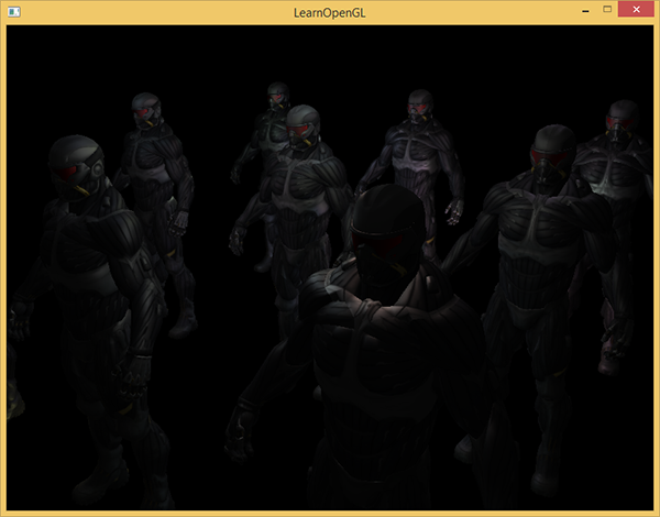
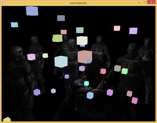
Running a simple demonstration with 32 small light sources looks like this:
One of the drawbacks of deferred lighting is the impossibility of mixing, since all g-buffers for each pixel contain information about only one surface, while mixing uses combinations of several fragments. (Blending) translation . Another disadvantage of deferred lighting is that it forces you to use one method of calculating lighting that is common to all objects; although this limitation can be somehow circumvented by adding information about the material to the g-buffer.
To cope with these shortcomings (especially the lack of blending), rendering is often divided into two parts: deferred lighting rendering, and the second part with direct rendering is intended for superimposing something on the stage or using shaders that are not combined with deferred lighting. (Note lane. From examples: adding translucent smoke, fire, glass) To illustrate the work, we will draw light sources like small cubes by direct rendering, since the lighting cubes require a special shader (they are uniformly lit in one color).
We combine the deferred rendering with direct.
Suppose we want to draw each light source in the form of a 3d cube with the center coinciding with the position of the light source and emitting light with the color of the source. The first idea that comes to mind is direct rendering of cubes for each light source over the results of the pending rendering. Ie, we draw the cubes as usual, but only after deferred rendering. The code will look something like this:
// [...] RenderQuad(); // shaderLightBox.use(); shaderLightBox.setMat4("projection", projection); shaderLightBox.setMat4("view", view); for (unsigned int i = 0; i < lightPositions.size(); i++) { model = glm::mat4(); model = glm::translate(model, lightPositions[i]); model = glm::scale(model, glm::vec3(0.25f)); shaderLightBox.setMat4("model", model); shaderLightBox.setVec3("lightColor", lightColors[i]); RenderCube(); } These rendered cubes do not take into account the depth values from the deferred rendering and as a result, always draws on top of the already rendered objects: this is not what we are seeking.
First we need to copy the depth information from the geometric passage to the depth buffer, and only then draw the glowing cubes. Thus, fragments of glowing cubes will be drawn only if they are closer than the already drawn objects.
We can copy the contents of the framebuffer to another framebuffer using the glBlitFramebuffer function. We have already used this function in the example with smoothing: ( anti-aliasing ), translation . The glBlitFramebuffer function copies the user-specified part of the framebuffer to the specified part of another framebuffer.
For objects drawn in the deferred aisle, we retained the depth in the g-buffer of the framebuffer object. If we simply copy the contents of the g-buffer depth buffer to the default depth buffer, the luminous cubes will be drawn as if the entire scene geometry was drawn using a direct rendering pass. As briefly explained in the anti-aliasing example, we need to set up framebuffers for reading and writing:
glBindFramebuffer(GL_READ_FRAMEBUFFER, gBuffer); glBindFramebuffer(GL_DRAW_FRAMEBUFFER, 0); // - glBlitFramebuffer( 0, 0, SCR_WIDTH, SCR_HEIGHT, 0, 0, SCR_WIDTH, SCR_HEIGHT, GL_DEPTH_BUFFER_BIT, GL_NEAREST ); glBindFramebuffer(GL_FRAMEBUFFER, 0); // [...] Here we copy the entire contents of the framebuffer depth buffer into the default depth buffer (If necessary, you can copy the color buffers or the stensil buffer in the same way). If we now render the glowing cubes, they will be drawn as if the geometry of the scene is real (although it is drawn as simple).

The source code of the demo can be found here .
With this approach, we can easily combine deferred rendering with direct. This is excellent, as we will be able to apply mixing and drawing objects that require special shaders that are not applicable when deferring rendering.
More light sources
Delayed lighting is often praised for the ability to draw a huge number of light sources without a significant reduction in performance. The delayed illumination in itself does not allow to draw a very large number of light sources, since we still have to count the contribution of all light sources for each pixel. To draw a huge number of light sources, a very beautiful optimization is used, applicable to the deferred rendering - the scope of the light sources. (light volumes)
Usually, when we draw fragments in a highly illuminated scene, we take into account the contribution of each light source on the scene, regardless of its distance from the fragment. If most of the light sources never affect the fragment, why do we spend time on calculations for them?
The idea of the scope of the light source is to find the radius (or volume) of the light source - that is, the area in which the light is able to reach the surface. Since most light sources use some kind of attenuation, we can find the maximum distance (radius) the light can reach. After that, we perform complex calculations of illumination only for those light sources that affect this fragment. This saves us from a huge amount of computation, since we calculate the lighting only where it is needed.
With this approach, the main trick is to determine the size of the field of action of the light source.
The calculation of the scope of the light source (radius)
To obtain the radius of the light source, we must solve the attenuation equation for the brightness, which we consider dark - it can be 0.0 or something slightly more illuminated, but still dark: for example, 0.03. To demonstrate how to calculate the radius, we will use one of the most complex, most common attenuation functions from the light caster example.
We want to solve this equation for the case when i.e. when the light source is completely dark. However, this equation will never reach the exact value of 0.0, so there is no solution. However, we can instead solve the equation for brightness for a value close to 0.0, which can be considered almost dark. In this example, we consider acceptable brightness value in - divided by 256, since the 8-bit framebuffer can contain 256 different brightness values.
The selected attenuation function becomes almost dark at a distance of the range, if we limit it to a lower brightness than 5/256, then the scope of the light source will become too large - this is not so effective. Ideally, a person should not see a sudden sharp border of light from a light source. Of course, this depends on the type of scene, a higher minimum brightness value gives smaller areas of light sources and increases the efficiency of calculations, but can lead to noticeable artifacts in the image: the lighting will be sharply cut off at the boundaries of the light source action area.
The damping equation that we need to solve becomes:
Here - the brightest component of the light (of the r, g, b channels). We use the brightest component, since the other components will have a weaker limit on the scope of the light source.
Continue to solve the equation:
The last equation is a quadratic equation in the form with the following solution:
We obtained a general equation that allows us to substitute parameters (constant attenuation coefficients, linear and quadratic) in order to find x, the radius of the source of light.
float constant = 1.0; float linear = 0.7; float quadratic = 1.8; float lightMax = std::fmaxf(std::fmaxf(lightColor.r, lightColor.g), lightColor.b); float radius = (-linear + std::sqrtf(linear * linear - 4 * quadratic * (constant - (256.0 / 5.0) * lightMax))) / (2 * quadratic); The formula returns a radius between approximately 1.0 and 5.0, depending on the maximum brightness of the light source.
We find this radius for each light source on the scene and use it in order to take into account for each fragment only those light sources within the scope of which it is located. Below is a converted lighting passage that takes into account the areas of action of light sources. Please note that this approach is implemented only for training purposes and is poorly suited for practical use (we will discuss why soon).
struct Light { [...] float Radius; }; void main() { [...] for(int i = 0; i < NR_LIGHTS; ++i) { // float distance = length(lights[i].Position - FragPos); if(distance < lights[i].Radius) { // [...] } } } The result is exactly the same as before, but now for each light source, its effect is taken into account only within its area of operation.
The real application of the scope of the light source.
The fragment shader shown above will not work in practice and serves only to illustrate how we can get rid of unnecessary lighting calculations. In reality, the video card and the GLSL shader language optimizes loops and branching very poorly. The primary reason for this is that the execution of the shader on the video card is performed in parallel for different pixels, and many architectures impose a restriction that, when executed in parallel, different streams must compute the same shader. Often this leads to the fact that a running shader always calculates all the branches, so that all shaders work the same time. (Taken by the lane. This does not affect the result of the calculations, but it can reduce the performance of the shader.) Because of this, it may turn out that our radius check is useless: we will still calculate the lighting for all sources!
A suitable approach for using the light effect area is to render the spheres with a radius as the light source. The center of the sphere coincides with the position of the light source, so that the sphere contains within itself the scope of the light source. There is a small trick here - we use basically the same pending fragmentary shader to draw a sphere. When drawing a sphere, the fragment shader is called just for those pixels affected by the light source, we render only the right pixels and skip all the others. The picture in the picture below:

, . , , . _*__
_ + __ , .
: ( ) , , , - ( ). stenil .
, , , . ( ) : c (deferred lighting) (tile-based deferred shading) . MSAA. .
vs
( ) - , , . , — , MSAA, .
( ), ( g- ..) . , .
: , , , . , , , . . parallax mapping, , . , .
Additional links
- Tutorial 35: Deferred Shading — Part 1 — OGLDev . .
- Deferred Rendering for Current and Future Rendering Pipelines : c Andrew Lauritzen (tile-based deferred shading) c (deferred lighting) .
PS - . , !
Source: https://habr.com/ru/post/420565/
All Articles