The book "Site Reliability Engineering. Reliability and reliability as in Google "
 For nearly 20 years, Google has been providing unimaginably complex and large-scale systems that are responsive to user requests. The Google search engine finds the answer to any questions in a split second, Google maps accurately reflect the earth's landscape, and Google Mail is available in 365/24/7 mode and, in effect, has become the first public cloud storage. Are these systems flawless? No, they also refuse, break and become obsolete, like any technique. We just do not notice. The fact is that for more than ten years, Google has been developing the unique technology of Site Reliability Engineering, which ensures uninterrupted operation and the ongoing development of software systems of any complexity. This book is a storehouse of experience accumulated by Google over the years, the collective work of many outstanding specialists and an indispensable resource for any engineer who wants to develop and maintain any products as efficiently and efficiently as possible.
Google's exploitation environment from an SRE perspective
Google’s data centers (data centers) are significantly different from traditional data centers and small server farms. These differences introduce additional challenges as well as additional features. This chapter discusses the challenges and opportunities specific to Google's data centers, and introduces terminology that will be used throughout the book.
Equipment
Most of Google’s computing resources are located in company-designed data centers that have their own power supply system, cooling system, internal network and computing equipment [Barroso et al., 2013]. Unlike typical data centers provided by providers to their customers, all Google data centers are equipped equally. To avoid confusion between server hardware and server software, we use the following terminology in this book:
')
- a machine (computer) is a piece of equipment (or perhaps a virtual machine);
- A server is a unit of software that implements a service.
Any server can be running on the machines, so we do not allocate specific computers for specific server programs. For example, we do not have a specific machine running a mail server. Instead, resources are allocated by our Borg cluster management system.
We understand that such use of the term “server” is non-standard. It’s more customary to refer to two concepts at once: a program that serves network connections, and at the same time a machine that runs such programs, but when we talk about Google’s computing power, the difference between these two concepts is significant. Once you get used to our interpretation of the word "server", you will understand why it is important to use such specialized terminology not only directly in Google, but throughout this book.
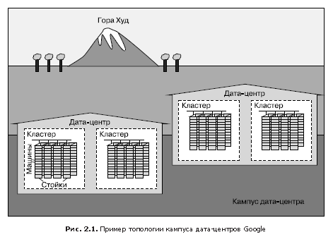
In fig. 2.1 demonstrated the configuration of the Google data center.
- Dozens of cars are placed on racks.
- Racks stand in rows.
- One or more rows form a cluster.
- Typically, a data center building (data center), or data center, hosts several clusters.
- Several buildings of data centers, which are located close to each other, make up the campus.
Inside each data center, all machines must be able to communicate effectively with each other, so we have created a very fast virtual switch with tens of thousands of ports. This was accomplished by connecting hundreds of Google-developed switches into a “factory” based on the Clos network topology [Clos, 1953], called Jupiter [Singh et al., 2015]. In its maximum configuration, Jupiter supports 1.3 PB / s bandwidth between servers.
Data centers are connected to each other using our global backbone network B4 [Jain et al., 2013]. B4 has a software-configured network architecture and uses the open communication protocol OpenFlow. B4 provides a wide bandwidth to a limited number of systems and uses flexible channel width control to maximize its average value [Kumar et al., 2015].
System software that "organizes" equipment
Software that manages and administers our equipment must be able to handle systems of enormous scale. Hardware failures are one of the main problems solved by software. Given the large number of hardware components in the cluster, they occur quite often. In each cluster, thousands of machines usually fail within a year and thousands of hard drives fail. If you multiply this number by the number of clusters operating throughout the world, the result is staggering. Therefore, we want to isolate users from such problems, and the teams involved in our services also do not want to be distracted by hardware problems. Each campus data centers have teams responsible for maintaining the equipment and infrastructure of the data center.
Machine control
Borg (Fig. 2.2) is a distributed cluster management system [Verma et al., 2015], similar to Apache Mesos. Borg manages jobs at the cluster level.
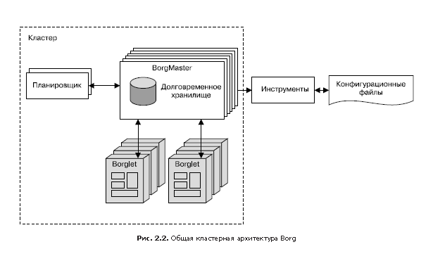
Since tasks are freely distributed between machines, we cannot use IP addresses and port numbers to access them. This problem is solved by an additional level of abstraction: when starting a task, Borg allocates a name for the task and a number (index) for each of its tasks using the Borg Naming Service (BNS). Instead of using the IP address and port number, other processes are associated with Borg tasks by their BNS name, which BNS then converts to an IP address and port number. For example, the BNS path may be a string like / bns / <cluster> / <user> / <task_name> / <task_number>, which is then translated (in networks it is accepted to say "allowed") in the format <IP address>: <port> .
Borg is also responsible for assigning resources for assignments. Each task must indicate which resources are required to complete it (for example, three processor cores, 2 GB of RAM). Using the list of requirements for all tasks, Borg can optimally distribute tasks among machines, taking into account fault tolerance considerations as well (for example, Borg will not run all tasks of the same task on the same rack, as the switch of this rack in case of failure will be a critical point for this tasks).
If a task attempts to capture more resources than requested, Borg destroys it and then restarts (because it is usually preferable to have a task that sometimes crashes and restarts than does not restart at all).
Storage
For faster access to data, tasks can use a local disk of machines, but we have several options for organizing persistent storage in a cluster (and even locally stored data will eventually be transferred to cluster storage). They can be compared to Luster and Hadoop Distributed File System (HDFS), clustered file systems that have an open source implementation.
The storage provides users with easy and reliable access to data available to the cluster. As shown in fig. 2.3, the repository has several layers.

1. The bottommost layer is called D (from disk, although D level uses both traditional hard drives and flash drives). D is a file server running on almost all cluster machines. However, users who want to access their data do not want to remember which machine they are stored on, so the next layer is connected here.
2. Above layer D is the Colossus layer, which creates a file system in a cluster, offering the usual file system semantics, as well as replication and encryption. Colossus is the heir to GFS, the Google File System (Google file system) [Ghemawat et al., 2003].
3. Further, there are several database services similar to those built above the Colossus level.
- Bigtable [Chang et al., 2006] is a non-relational (NoSQL) database system capable of working with petabyte-size databases. Bigtable is a sparse distributed, fault-tolerant, multi-dimensional ordered database that is indexed by row, column, and timestamp keys; each database value is an arbitrary uninterpreted array of bytes. Bigtable also supports replication between data centers.
- Spanner [Corbett et al., 2012] offers a SQL-like interface for users who require data integrity and consistency when accessing from anywhere in the world.
- Some other database systems are available, such as Blobstore. All of them have their advantages and disadvantages (see Chapter 26).
Network
Google network equipment is managed in several ways. As mentioned earlier, we use a software-configurable network based on OpenFlow. Instead of “smart” routers, we use less expensive “stupid” switches in conjunction with a central (duplicated) controller, which pre-calculates the best route on the network. This makes it possible to use simpler switching equipment, freeing it from the time-consuming search for a route.
Network bandwidth should be properly distributed. As Borg limits the computing resources that a task can use, so Bandwidth Enforcer (BwE) controls the available bandwidth to maximize the average bandwidth. Optimization of bandwidth is not only associated with cost: centralized traffic management allows you to solve a number of problems that are extremely difficult to solve with a combination of distributed routing and conventional traffic management (Kumar, 2015).
Some services have tasks running on several clusters located in different parts of the world. In order to reduce the latency of globally distributed systems, we would like to send users to the nearest data center that has the appropriate capacity. Our Global Software Load Balancer (GSLB) performs load balancing at three levels:
- geographic load balancing for DNS queries (for example, to www.google.com ), it is described in chapter 19;
- load balancing at the level of user services (for example, YouTube or Google Maps);
- load balancing at the level of remote procedure calls (Remote Procedure Call, RPC), described in Chapter 20.
The owners of the services give them symbolic names, a list of BNS server addresses and the performance available at each site (usually measured in queries per second - queries per second, QPS). In the future, GSLB sends traffic to the specified BNS addresses.
Other system software
There are other important components in the data center software.
Lockout service
The Chubby lock service [Burrows, 2006] provides an API similar to the file system and designed to handle locks. Chubby handles blocking of all data centers. It uses the Paxos protocol for asynchronous access to Consensus (see Chapter 23).
Chubby also plays an important role when choosing a wizard. If for some service, in order to increase reliability, there are five replicas of the task, but at a particular moment only one of them does the real work, then Chubby is used to select this replica.
Chubby is great for data that requires storage reliability. For this reason, BNS uses Chubby to store the ratio of BNS paths and IP address: port pairs.
Monitoring and Alert
We want to be sure that all services work as they should. Therefore, we run multiple instances of the Borgmon monitoring program (see chapter 10). Borgmon regularly receives benchmark values from monitored services. This data can be used immediately for notification or saved for further processing and analysis, for example for plotting graphs. Such monitoring can be used for such purposes as:
- configure alerts for urgent problems;
- behavior comparison: did the software update speed up the server;
- assessment of the nature of the change in resource consumption over time, which is necessary for capacity planning.
Our software infrastructure
The architecture of our software is designed so that you can most effectively use the hardware resources of the system. All of our code is multi-threaded, so one task can easily involve multiple cores. In order to support dashboards, monitoring and debugging, each server includes the implementation of an HTTP server as an interface through which diagnostic information and statistics are provided for a specific task.
All Google services “communicate” using the Remote Procedure Call (RPC) infrastructure, called Stubby. There is its open source version, it is called gRPC (see grpc.io ). Often an RPC call is made even for subroutines in a local program. This allows the program to reorient to calls to another server in order to achieve greater modularity or as the initial amount of server code grows. GSLB can perform RPC load balancing in the same way as for external service interfaces.
The server receives RPC requests from the front end and sends the RPC to the backend. Using traditional terms, the frontend is called the client, and the backend is called the server.
Data is transferred to and from the RPC via the serialization protocol — the so-called protocol buffers, or, briefly, protobufs. This protocol is similar to Apache's Thrift and has several advantages over XML when it comes to serializing structured data: it is simpler, three to ten times more compact, 20 to 100 times faster and more unambiguous.
Our development environment
The speed of product development is very important for Google, so we created a special environment that makes the most of its infrastructure (Morgenthaler et al., 2012).
With the exception of a few groups whose products are open source, and therefore they use their own separate repositories (for example, Android and Chrome), Google’s software engineers work in one common repository [Potvin, Levenberg, 2016]. This approach has several practical applications that are important to our manufacturing process.
- If an engineer encounters a problem in a component outside of his project, he can correct the problem, send the proposed changes (the “change list” - changelist, CL) to the owner for review and then implement the changes made to the main program branch.
- Changes to the source code in the engineer’s own project require consideration - an audit (review). All the software before the adoption passes this stage.
When software is assembled, a build request is sent to specialized servers of the data center. Even building large projects is fast, because you can use multiple servers for parallel compilation. This infrastructure is also used for continuous testing. Every time a new list of changes (CL) appears, tests of the entire software that are affected by these changes, directly or indirectly, are performed. If the framework detects that changes have disrupted other parts of the system, it notifies the owner of these changes. Individual projects use the push-on-green system (“send upon success”), according to which the new version is automatically sent to commercial operation after passing the tests.
Shakespeare: a sample service
To demonstrate how Google’s service is deployed in a commercial operating environment, consider an example of a hypothetical service that interacts with Google technologies. Suppose that we want to offer a service that allows you to determine in which works of Shakespeare you find the word you specified.
We can divide the system into two parts.
- A batch processing component that reads all Shakespeare texts creates an index and writes it into a Bigtable. This task (more precisely, the task) is carried out only once or, possibly, occasionally (after all, some new text of Shakespeare may be discovered!).
- A frontend application that processes end-user requests. This task is always running, because at any given time a user from any time zone may want to search Shakespeare’s books.
The batch processing component will be MapReduce, whose work is divided into three phases.
1. In the Mapping phase, Shakespeare texts are read and broken into separate words. This part of the work will be done faster if you run multiple workflows (tasks) in parallel.
2. In the shuffle phase, entries are sorted by words.
3. In the Reduce phase, view tuples are created (word, playlist).
Each tuple is written as a string in the Bigtable, the key is the word.
Request life cycle
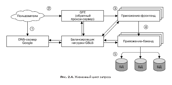
In fig.2.4 shows how the user request is served. First, the user navigates to the browser using the link shakespeare.google.com. To obtain the corresponding IP address, the user's device transmits (“resolves”) the address using the DNS server (1). The DNS query eventually ends up on Google’s DNS server, which communicates with GSLB. By tracking the traffic load of all front-end servers by region, GSLB chooses which server IP address to return to the user.
The browser connects to the HTTP server at the specified address. This server (it is called Google Frontend or GFE) is a “reverse” proxy server (reverse proxy) located on the other end of the client’s TCP connection (2). The GFE searches for the required service (for example, it can be a search service, maps, or — in our case, the Shakespeare service). Repeatedly accessing GSLB, the server finds an available Shakespeare front-end server and accesses it through a remote procedure call (RPC), sending an HTTP request received from the user (3).
The Shakespeare server analyzes the HTTP request and creates a “protocol buffer” (protobuf) containing the words to be found. Now, the Shakespeare front-end server should contact the Shakespeare backend server: the first one contacts the GSLB to get the BNS address of a suitable and unloaded instance of the second (4). Next, the Shakespeare backend server communicates with the Bigtable to receive the requested data (5).
The result is written to the response protobuf and returned to the Shakespeare backend server. The backend passes protobuf with the result of the service to the Shakespeare front end server, which creates an HTML document and returns it as an answer to the user.
This whole chain of events runs in the blink of an eye - in just a few hundred milliseconds! Since many components are involved, there are many places where an error could potentially occur; in particular, a failure in GSLB can disorganize all work and lead to collapse. However, Google’s policy of rigorous monitoring, comprehensive testing, and safe deployment of new software in addition to our proactive error recovery techniques (such as phasing out features) allows us to create reliable services that meet the expectations of our users. After all, people regularly go to www.google.com to check if they have an Internet connection.
Organization of tasks and data
Load testing showed that our backend server can handle about 100 requests per second (QPS). Trial operation with a limited number of users has shown that the peak load can reach approximately 3470 QPS, so we need to create at least 35 tasks. However, the following considerations say that we will need at least 37 tasks, or N + 2.
- During the update, one task will be temporarily unavailable, so 36 tasks will remain active.
- During the upgrade, there may be a hardware failure, which leaves only 35 tasks - just as long as it takes to maintain the peak load.
A more detailed study of user traffic reveals the geographical distribution of peak loads: 1430 QPS are generated from North America, 290 from South America, 1400 from Europe and 350 from Asia and Australia. Instead of placing all the back-end servers in one place, we distribute them across regions: in the USA, South America, Europe and Asia. Given the principle of N + 2 in each region, we get 17 tasks in the US, 16 in Europe and six in Asia. In South America, however, we decide to use four tasks (instead of five) to reduce costs — from N + 2 to N + 1. In this case, we are prepared to take a small risk of more delay and reduce the cost of equipment: by allowing GSLB when reloading a South American data center, redirect traffic from one continent to another, we can save 20% of resources,that would be spent on equipment. In larger regions, for additional sustainability, we distribute tasks between 2–3 clusters.
Since the backend server needs to communicate with the Bigtable data warehouse, we also need to strategically think about this storage. If Asia’s backend server contacts Bigtable located in the USA, it will lead to a significant increase in delays, so we duplicate Bigtable in each region. This gives us additional stability in case the Bigtable server fails, and also reduces the data access latency. And although Bigtable does not ensure strict correspondence of data between instances at any given time, duplication does not become a serious problem, because we do not need to update the contents of the repository too often.
So, in this chapter you are introduced to a variety of concepts and terms. Although you do not need to memorize them all, they can be useful in studying many other systems that we will look at next.
»More information about the book can be found on the publisher site.
» Table of Contents
» Excerpt
For Habrozhiteley a 20% coupon discount - Site Reliability Engineering
Source: https://habr.com/ru/post/420139/
All Articles